Advantech PPC-315W TGL User Manual
15.6"/21.5" panel pc with tft led and 11th gen intel core i processor
Hide thumbs
Also See for PPC-315W TGL:
- Startup manual (15 pages) ,
- Startup manual (15 pages) ,
- User manual (56 pages)

Related Manuals for Advantech PPC-315W TGL


Summary of Contents for Advantech PPC-315W TGL
- Page 1 User Manual PPC-315W/321W TGL 15.6"/21.5" Panel PC with TFT LED ® and 11th Gen Intel Core™ i Processor...
- Page 2 No part of this manual may be reproduced, copied, translated, or transmitted in any form or by any means without the prior written permission of Advantech Co., Ltd. The information provided in this manual is intended to be accurate and reliable.
- Page 3 (ESD) or electromagnetic interference (EMI) leakage, we strongly recommend using CE-compliant industrial enclosure products. Technical Support and Assistance Visit the Advantech website at http://support.advantech.com to obtain the latest product information. Contact your distributor, sales representative, or Advantech's customer service center for technical support if you need additional assistance. Please have the following information to hand before calling: –...
- Page 4 Warning: Ensure that the voltage of the power source is correct before connect- ing the equipment to a power outlet. The power outlet socket should have a grounded connection. Avertissement: Assurez-vous que la tension de la source d’alimentation est cor- recte avant de connecter l’appareil à...
- Page 5 AVERTISSEMENT: Ces instructions sont fournies conformément aux normes IEC 704-1. Advantech decline toute responsabilité quant à la précision de toute déclaration contenue dans le présent document. Do not expose the equipment to direct sunlight, or install the equipment in an environment with direct sunlight, as this may cause damage.
- Page 6 Manual Conventions Warning! Warnings indicate conditions that, if not observed, can cause personal injury! Caution! Cautions are included to prevent hardware damage and data loss. For example, “Batteries are at risk of exploding if replaced with an incor- rect type. Replace only with the same or equivalent type recommended by the manufacturer.
-
Page 7: Table Of Contents
Rear Panel ....................3 Figure 1.2 Rear Panel..............3 Panel Bottoms................... 3 Figure 1.3 Panel PC Bottom ............3 Dimensions ....................4 Figure 1.4 PPC-315W TGL Dimensions........4 Figure 1.5 PPC-321W TGL Dimensions........4 Specifications .................... 5 Ordering Information ................. 6 Chapter System Installation and Setup ...7... - Page 8 2.3.4 Stand Mounting................20 Figure 2.27VESA Mount Screw Holes........21 Figure 2.28Securing the VESA Mount Base ......21 Figure 2.29Securing the VESA Mount Bracket ......22 Figure 2.30Securing the Stand Mount Hinge Cover....22 Figure 2.31Completed Stand Mount........... 23 2.3.5 Cabinet Installation and Grounding ..........
-
Page 9: Chapter 1 General Information
Chapter General Information This chapter details general infor- mation regarding PPC-315W/321W TGL. Introduction Specifications Dimensions... -
Page 10: Introduction
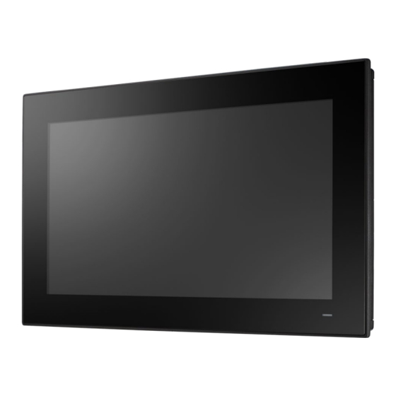
The PPC-315W/321W TGL front panel is a true-flat color TFT LCD touchscreen with Projected Capacitive Multi-Touch. The front panel is IP66 rated for dust and water tol- erance (Figure 1.1). Note: The examples provided in this manual are of the PPC-315W TGL model. Aluminum Frame... -
Page 11: Rear Panel
Rear Panel The PPC-315W/321W TGL rear panel features four VESA mount (100 x 100 mm/ 3.93 x 3.93 in) holes located on its bottom side, as demonstrated below: VESA mount screws: 4 x M4 screws, Screw depth: 12 mm (max.) Figure 1.2 Rear Panel Panel Bottoms The system’s I/O, located on the bottom of the device, (Figures 1.3) are listed below:... -
Page 12: Dimensions
Dimensions Figure 1.4 PPC-315W TGL Dimensions Figure 1.5 PPC-321W TGL Dimensions PPC-315W/321W-TGL User Manual... -
Page 13: Specifications
Specifications PPC-321W PPC-315W LCD Panel 21.5” 15.6” Display Type TFT LCD (with LED backlight) TFT LCD (with LED backlight) Max. Resolution 1920 x 1080 1920 x 1080 Brightness 250 cd/m 450 cd/m Pixel Pitch 476.64 (H) x 268.11 (V) 344.2 (H) x 193.5 (V) 89 (left), 89 (right), 89 (up), 89 80 (left), 80 (right), 85 (up), 85 Viewing Angle... -
Page 14: Ordering Information
558.4 x 349.8 x 62.2 mm/21.9 x 419.7 x 269 x 61.1 mm/16.52 x Dimensions 13.7 x 2.4 in 10.59 x 2.44 in Weight 6.6 kg/14.6 lb 4.8 kg/10.7 lb Note! The test conditions for the power consumption values provided above were as follows: Memory: 16 GB DDR4 3200 HDD: 64 GB SSD... -
Page 15: Chapter 2 System Installation And Setup
Chapter System Installation and Setup Quick System Tour Memory Card Installation HDD Installation M.2 Installation Wireless LAN Card Installation Mounting the System... -
Page 16: Quick System Tour
Quick System Tour Before setting up the panel PC, take a moment to identify the locations of the device- controls, drives, connectors, and ports (as shown in Figure 2.3). When placed upright, the PPC-315W/321W TGL front panel should appear as shown in Figure 2.1. Since PPC-315W/321W TGL are series models, the following photos in the manual are PPC-315W examples. -
Page 17: Installation Procedures
Figure 2.3 Panel PC Bottom with I/O A. COM2: RS-232/422/485 B. 1 X Line out C. 2 x LAN D. 1 X HDMI E. 1 x USB3.2/1 x USB2.0 F. 2 x USB3.2 G. 1 x Type C H. COM1: RS-232 I. - Page 18 Install memory a. If install 2pcs memory, use the thermal pad thickness is 1.5mm the bottom, the middle and top thermal pad thinness is 1.0mm. Remember to scrap the pro- tect film before use the thermal pad. Figure 2.5 Memory Card Installation b.
-
Page 19: Install Ssd
2.2.2 Install SSD Remove the screw of rear cover. Remove 4 screws of HDD bracket. Figure 2.7 Retention Screws on HDD Bracket Take out screws and cable from accessory box. Figure 2.8 HDD Module Bracket Insert cable to SSD. Figure 2.9 SATA Cable Connected to SATA HDD PPC-315W/321W-TGL User Manual... -
Page 20: Install M.2 Devices
Assemble SSD on the bracket. Figure 2.10 Secure SATA HDD with Screws Install the SSD kit to machine. Figure 2.11 SATA HDD Connected to the Motherboard 2.2.3 Install M.2 Devices Remove rear cover. Assemble M.2 on motherboard. Figure 2.12 M.2 Installation PPC-315W/321W-TGL User Manual... -
Page 21: Install Wifi Module
Take out the thermal pad from accessory box, and stick on M.2. Figure 2.13 Stick Thermal Pad on M.2 2.2.4 Install WiFi module Remove rear cover. Assemble antenna bracket on antenna cable. Figure 2.14 Assemble Bracket with Antenna Cable PPC-315W/321W-TGL User Manual... - Page 22 Assemble WiFi card. Figure 2.15 Assemble WiFi Card Assemble the rear cover, and install antenna. Figure 2.16 Assemble WiFi Antenna PPC-315W/321W-TGL User Manual...
-
Page 23: System Power On
2.2.5 System power on A 2-pin power connector is included in the accessory box. Connect the power con- nector to 12-30VDC power lines and plug the power lines into the system power receptor. DC power source shall be complied with ES1 requirements, output rating is 12-30Vdc, 8-4A, with minimum operating temperature 50°C, and has to be evaluated according to IEC/UL 60950-1 and/or IEC/UL 62368-1. -
Page 24: Mounting The System
Mounting the System Warning! When mounting the panel PC, more than one person should perform the installation to prevent accidental damage to the panel or personal injury. Le comité constate qu’el-nasr “mounting, Plus d’une personne installa- tion to prevent the cadre accidental damage to the personal injury. The panel PC supports various mounting options, as listed below. - Page 25 Insert four M4 screws into the holes on the panel PC and tighten them to secure the bracket to the rear panel. Figure 2.19 Rear Panel Screw Locations Warning! Ensure that the thread depth of the screws on the rear panel does not exceed 4 mm (0.15 in).
-
Page 26: Panel Mounting
PPC-315W-XBXX: 413 x 262 mm/16.26 x 10.31 in Insert the panel PC into the cutout. Retrieve the hook brackets and M6 x 21L screws from the accessory box (10 for PPC-315W TGL; 12 for PPC-321W TGL). Veuillez installer le panneau PC dans la découpe. Récupérez les crochets et les vis M6 x 21L de la boîte à... - Page 27 Insert the hook brackets into the holes following the direction of the arrows shown in Figure 2.25 and hang the panel PC. Figure 2.23 Hook Brackets Location Tighten the screws to secure the panel PC in place (Figure 2.26). Figure 2.24 Fasten the Hook Bracket Figure 2.25 Panel Mount Rear View (Take PPC-315W drawing as example) PPC-315W/321W-TGL User Manual...
-
Page 28: Arm Mounting
2.3.3 Arm Mounting PPC-315W/321W TGL can be mounted on a VESA-compliant arm mount with a 100 mm (3.93 in) interface pad. To affix the panel PC to an arm mount, follow the steps below. Refer to the installation instruction of the mounting arm to correctly mount the arm onto the surface as a base. - Page 29 To mount the panel PC onto the stand, follow the steps below: Use four M4 x 8L screws to affix the VESA bracket to the panel PC. Users can choose 100 x 100 mm (3.93 x 3.93 in) VESA mount according to their require- ments.
- Page 30 Use four M4 x 6L screws to secure the mount stand to the VESA mount bracket. Figure 2.29 Securing the VESA Mount Bracket Use one M4 x 5L screw to secure the stand mount hinge cover. Figure 2.30 Securing the Stand Mount Hinge Cover PPC-315W/321W-TGL User Manual...
-
Page 31: Cabinet Installation And Grounding
Figure 2.31 Completed Stand Mount 2.3.5 Cabinet Installation and Grounding Follow these instructions to install the PPC system, and pay attention to the ground pin which should be connected to the earth/ground. PPC system should give the best performance for EMI optimum EMI immunity, ESD immunity, surge immunity, and system isolation. - Page 32 System wiring. Figure 2.33 System Wiring Cabinet Step A: Connect the cabinet to the earth/ground. Step B: Ensure that all cabinets have been grounded together. Step C: Connect the ground of the power supply to the cabinet. Step D: Connect the ground pin of PPC system to the cabinet. Step E: Connect the I/O to the controller if needed.
-
Page 33: Jumper Settings
Chapter Jumper Settings Jumpers and Connectors External COM Ports and Pin Definitions... -
Page 34: Motherboard Jumpers And Connectors
Motherboard Jumpers and Connectors Motherboard connectors is provided below (Figure 3.1). The internal peripheral con- nectors are accessible when the motherboard is outside of the chassis. Figure 3.1 Motherboard The internal jumpers and connectors on the motherboard, and their pinouts, are listed in the table below. -
Page 35: Rtc Select
3.1.2 RTC Select Function 1-2pin Normal (Default*) 2-3pin Clear CMOS 3.1.3 ATX/AT Select Function 2-3pin ATX power (Default*) 1-2pin AT power 3.1.4 Touch Power Select Function Open Closed Note: Resistive touch model JP3 need add jumper, projected capacitive touch model JP3 need pull off jumper. -
Page 36: External Com Ports And Pin Definitions
External COM Ports and Pin Definitions Figure 3.2 Location of COM1 and COM2 Ports COM1: RS-232 COM1 Pin 9 is set as “RI” by default. This setting can be changed to 5V or 12V output using a jumper. COM2: RS-232/422/485 Note! COM2 does not support ring function. -
Page 37: Software Setup
Chapter Software Setup Driver Installation BIOS Setup Program... -
Page 38: Driver Installation
Driver Installation Before installing software on the panel PC, install the corresponding drivers to ensure full functionality. All drivers can be downloaded from the Advantech website: http://www.advantech.com BIOS Setup Utility 4.2.1 Main Setup You can enter BIOS setup utility by pressing “Delete”. -
Page 39: Advanced Bios Features Setup
4.2.2 Advanced BIOS Features Setup Following is COM2 Mode Selection (RS232/RS422/RS485): Select NCT6126D Super IO Configuration in the Advanced tab. Select Serial Port 2 Configuration option. PPC-315W/321W-TGL User Manual... - Page 40 Select Serial Port 2 Mode option to set the COM2 operation mode as RS232, RS422, or RS485. If COM2 mode is set as RS485, the RS485 Auto Flow control option can be Enabled or Disabled. PPC-315W/321W-TGL User Manual...
-
Page 41: Chipset Configuration
4.2.3 Chipset Configuration Following is Wake-on-LAN: Select PCH-IO Configuration option in the Chipset tab. Set the Wake On By option to Enabled. PPC-315W/321W-TGL User Manual... -
Page 42: Security
4.2.4 Security Set Administrator Password PPC-315W/321W-TGL User Manual... -
Page 43: Boot
4.2.5 Boot Setup Prompt Timeout This item allows users to set the number of seconds to wait for setup activation key. 65535 (oxFFFF) means indefinite waiting. Bootup NumLock State This item allows users to select the keyboard NumLock state. Quiet Boot ... -
Page 44: Save And Exit
4.2.6 Save and Exit Save Charges and Exit This item allows users to exit the system setup after saving changes. Discard Changes and Exit This item allows users to exit the system setup without saving changes. Save Changes and Reset ... -
Page 45: Bsmi Rohs
Appendix BSMI RoHS... - Page 46 Note 3. “-” indicates that the restricted substance corresponds to the exemption. 製造商:研華股份有限公司 地址:台北市內湖區瑞光路 26 巷 20 弄 1 號 電話:02-27927818 Manufacturer: ADVANTECH Co., Ltd. Address: No. 1 Alley 20 Lane 26, Rueiguang Rd., Neihu District, Taipei City Telephone: 02-27927818 PPC-315W/321W-TGL User Manual...
- Page 47 Appendix BSMI Series Models...
- Page 48 PPC-315W 產品附錄型號 PPC-315W-PB50A PPC-315W-PB50AU PPC-315W-PB30A PPC-315W-PB30AU PPC-315W-PB70A PPC-315W-PB70AU PPC-315W-PB50B PPC-315W-PB30B PPC-315W-PB70B PPC-315W-PB50BU PPC-315W-PB30BU PPC-315W-PB70BU PPC-315W-PB50C PPC-315W-PB30C PPC-315W-PB70C PPC-315W-PB50CU PPC-315W-PB30CU PPC-315W-PB70CU PPC315WPB2201-T PPC315WPB2202-T PPC315WPB2203-T PPC315WPB2301-T PPC315WPB2302-T PPC315WPB2303-T PPC315WPB2304-T PPC315WPB2305-T PPC315WPB2306-T PPC315WPB2401-T PPC315WPB2402-T PPC315WPB2403-T PPC315WPB2404-T PPC315WPB2405-T PPC315WPB2406-T PPC315WPB2501-T PPC315WPB2502-T PPC315WPB2503-T PPC315WPB2504-T PPC315WPB2505-T PPC315WPB2506-T PPC315WPB2601-T PPC315WPB2602-T...
- Page 49 PPC-315W/321W-TGL User Manual...
- Page 50 No part of this publication may be reproduced in any form or by any means, such as electronically, by photocopying, recording, or otherwise, without prior written permission from the publisher. All brand and product names are trademarks or registered trademarks of their respective companies. © Advantech Co., Ltd. 2023...
Need help?
Do you have a question about the PPC-315W TGL and is the answer not in the manual?
Questions and answers