
Related Manuals for Advantech PPC-3150


Summary of Contents for Advantech PPC-3150
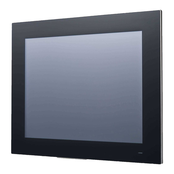
- Page 1 User Manual PPC-3150/3170 Intel® Atom E3845 Processor based panel PC, with 15"/17" color TFT LCD display...
- Page 2 No part of this manual may be reproduced, copied, translated or transmitted in any form or by any means without the prior written permission of Advantech Co., Ltd. Information provided in this manual is intended to be accurate and reliable. How- ever, Advantech Co., Ltd.
-
Page 3: Declaration Of Conformity
This product has passed the CE test for environwaremental specifications when shielded cables are used for external wiring. We recommend the use of shielded cables. This kind of cable is available from Advantech. Please contact your local sup- plier for ordering information. -
Page 4: Safety Instructions
The sound pressure level at the operator's position according to IEC 704-1:1982 is no more than 70 dB (A). DISCLAIMER: This set of instructions is given according to IEC 704-1. Advantech disclaims all responsibility for the accuracy of any statements contained herein. - Page 5 The power is fit for areas with an altitude of 5000 M below. Battery Information Batteries, battery packs, and accumulators should not be disposed of as unsorted household waste. Please use the public collection system to return, recycle, or treat them in compliance with the local regulations. 。 PPC-3150/3170 User Manual...
- Page 6 PPC-3150/3170 User Manual...
-
Page 7: Table Of Contents
Environwarement Specifications........... 4 1.2.6 Certification Specifications............4 1.2.7 IP ....................4 Dimensions ....................5 Figure 1.1 PPC-3150 dimensions..........6 Figure 1.2 PPC-3170 dimensions..........8 Chapter System Installation & Setup ....9 Quick Installation Guide ................10 Figure 2.1 Front Panel ............... 10 Figure 2.2 Side View.............. - Page 8 4.2.6 Wake on LAN................56 4.2.7 AT & ATX Setup ................. 60 4.2.8 OS Selection................61 4.2.9 SATA Mode Selection..............62 4.2.10 Boot Options ................63 Appendix A PCI/PCIE Photos ....... 65 PCI/PCIE Photos ..................66 PPC-3150/3170 User Manual viii...
-
Page 9: Chapter 1 General Information
Chapter General Information This chapter gives background information on PPC-3150/3170 panel PC. Sections include: Introduction Specifications Dimensions... -
Page 10: Introduction
Introduction The PPC-3150&3170 with 15”&17” Fanless panel PC doesn’t only deliver high per- formance by Intel Atom processor but also supports a wide operating temp. (-20 ~ ) and wide range of power input (9 ~ 32 Vdc). It consolidates performance and °... -
Page 11: General Specifications
30 W (Test system: Win7 32 bit) sumption Output Power 50 W 9 ~ 32 V , 6 A ~ 2 A Input Voltage Note! For test conditions for above power consumption, please refer to Note 1 and Note 2. PPC-3150/3170 User Manual... -
Page 12: Touchscreen Specifications
MSATA: MSATA 32G MLC E3845 32 bit IO: COM Port RS232 loopback 2M 1.91G x 4, USB 3.0 x 1, USB 2.0 x 4 Note 2: Test conditions of power consumption for PPC-3150: Test Test Power Test Configuration Condition System... -
Page 13: Dimensions
Dimensions PPC-3150: PPC-3150/3170 User Manual... -
Page 14: Figure 1.1 Ppc-3150 Dimensions
Unit: mm Figure 1.1 PPC-3150 dimensions Warning! Fixed VESA screw specification: M4; screw depth: 8 mm (Max). Use suitable mounting apparatus to avoid risk of injury. PPC-3150/3170 User Manual... - Page 15 PPC-3170: PPC-3150/3170 User Manual...
-
Page 16: Figure 1.2 Ppc-3170 Dimensions
Unit: mm Figure 1.2 PPC-3170 dimensions Warning! Fixed VESA screw specification: M4; screw depth: 8 mm (Max). Use suitable mounting apparatus to avoid risk of injury. PPC-3150/3170 User Manual... -
Page 17: Chapter 2 System Installation & Setup
Chapter System Installation & Setup Sections include: Quick Installation Guide Installation Procedures Installing HDD Installing Mini SATA Install Wireless LAN Card Install Riser Card AT/ATX Function Switch Hook Installation Installing Optional Modules... -
Page 18: Quick Installation Guide
(Network status LED) LAN LED (HDD status LED) HDD LED (Power status LED) POWER LED LAN LED Status HDD LED POWER LED LAN1 LAN2 Power off (S5) Power on Yellow Green Yellow Green (S0) (Operating, blinking) (Operating, blinking) (Operating, blinking) PPC-3150/3170 User Manual... -
Page 19: Figure 2.2 Side View
Figure 2.2 Side View Antenna hole Panel mounting hook hole Speakers (right and left) CPU heatsink Optional module expansion slot Note! Fixed VESA screw specification: M4; screw depth: 8 mm (Max). PPC-3150/3170 User Manual... -
Page 20: Figure 2.3 I/O Connectors
B: Line_out/Mic-in G: Power button C: 2 x Giga Ethernet ports H: DC jack and AT/ATX switch D: Display port I: VGA port E: 2 x RS-232 port J: 1 x USB 3.0 + 3 x USB 2.0 PPC-3150/3170 User Manual... -
Page 21: Installation Procedures
Connect Keyboard and Mouse Connect the keyboard and mouse to panel PC’s I/O interfaces. 2.2.2.1 Connecting Power The power button is located in the right bottom side of the panel PC. Note! Power cable and adapter are optional. PPC-3150/3170 User Manual... -
Page 22: Install Memory Card
Install Memory Card Remove the 11 screws and take down the 4 plugs of the rear cover. (See Figure 2.5 and 2.6) Figure 2.5 Figure 2.6 PPC-3150/3170 User Manual... - Page 23 Insert the memory card into the slot as indicated in the red square below, and take out the thermal pad for the memory and CPU from the accessory box, then the installation of memory card is finished. (See Figure 2.11) Figure 2.8 PPC-3150/3170 User Manual...
-
Page 24: Installing Hdd
Remove the 11 screws on rear cover and take down the 4 plugs. (See Figure 2.5 and 2.6) Remove the four screws on VESA ironware. (See Figure 2.9) Figure 2.9 Unscrew the four screws on HDD ironware and remove it. (See Figure 2.10) Figure 2.10 PPC-3150/3170 User Manual... -
Page 25: Figure 2.13
Take out 4 screws from the accessory box and fix them to the HDD ironware bracket (See Figure 2.11). Then take out the HDD data cable from the acces- sory box and connect it to the HDD, the assembled HDD module is shown as Figure 2.12. Figure 2.11 Figure 2.12 PPC-3150/3170 User Manual... -
Page 26: Installing Minisata
Relock the HDD bracket, and connect the data cable to the mainboard. (See Figure 2.13) Figure 2.13 Installing MiniSATA Follow installation steps 1 ~ 2 in the Section 2.4, and you’ll see the disassem- bled machine as shown in Figure 2.14. Figure 2.14 PPC-3150/3170 User Manual... -
Page 27: Figure 2.17
(See Figure 2.16) Then insert the short card into the correct mainboard slot, finally fix it with a screw and attach the thermal pad onto the card, which can both be found in the accessory box. (See Figure 2.17 and Fig- ure 2.18) Figure 2.16 PPC-3150/3170 User Manual... - Page 28 Figure 2.17 Figure 2.18 Follow disassemble steps to replace and fix VESA ironware and rear cover. PPC-3150/3170 User Manual...
-
Page 29: Install Wireless Lan Card
(See Figure 2.20) Then insert the short card into the correct mainboard slot, and fix it with a screw from the acces- sory box. (See Figure 2.21) Figure 2.20 PPC-3150/3170 User Manual... -
Page 30: Figure 2.23
Figure 2.21 Take down the antenna holder in the upper left corner and upper right corner of the machine. (See Figure 2.22) (This step is only for PPC-3150) Figure 2.22 PPC-3150/3170 User Manual... -
Page 31: Figure 2.25
Connect the cables of the wireless LAN card to the antenna holder. Please note the installation direction of the cable end and nut / washer. (See Figure 2.23) (This step is only for PPC-3150) Figure 2.23 Lock the assembled antenna holder onto the machine, and connect the cable to wireless LAN card. - Page 32 Relock the VESA ironware, and take down the two plugs of the top rear cover. (See Figure 2.25) Then return the rear cover and finish the installation of wire- less LAN card module and antenna. (See Figure 2.26) Figure 2.25 Figure 2.26 PPC-3150/3170 User Manual...
-
Page 33: Install Riser Card
PCIE to PCIE, which allows users to select by themselves. Figure 2.27 Remove the card slot shield and insert the card (see Figure 2.28), then tighten the screws and return the rear cover. Figure 2.28 PPC-3150/3170 User Manual... -
Page 34: At/Atx Function Switch
Note! The maximum dimension of the riser card is 176 mm x 107 mm for both PPC-3150 and PPC-3170. AT/ATX Function Switch The switch built into the machine, lets you choose between AT/ATX functions without removing the rear cover. (See Figure 2.29 and Figure 2.30) Figure 2.29 ATX Mode... -
Page 35: Hook Installation
Hook Installation Follow the figures below: Figure 2.31 PPC-3150/3170 User Manual... -
Page 36: Installing Optional Modules
2.10 Installing Optional Modules PPC-3150/3170 supports four optional modules: USB module, CFast module, CF module and COM module (See Figure 2.32). For detailed installation procedures, see Section A, B, C and D in the below. USB Module CFast Module CF Module COM Module Figure 2.32... -
Page 37: Figure 2.36
Figure 2.34 Remove the four screws on VESA ironware. (See Figure 2.35) Figure 2.35 PPC-3150/3170 User Manual... -
Page 38: Figure 2.37
Then tighten the two screws and connect the red SATA cables. (See Figure 2.37) The assembled CFast module is shown as Figure 2.38. Note! When installing CFast card, the iron try should be installed on the top. PPC-3150/3170 User Manual... -
Page 39: Figure 2.39
Figure 2.37 Figure 2.38 PPC-3150/3170 User Manual... -
Page 40: Figure 2.41
Take out a copper cylinder and fix it to the position marked with red circle in Fig- ure 2.39. Then take out a screw to secure MiniSATA to SATA Micro ATX board onto the position marked with red rectangle in FIgure 2.40. Figure 2.39 Figure 2.40 PPC-3150/3170 User Manual... -
Page 41: Figure 2.43
Then lock VESA ironware as shown in Figure 2.43. Lastly, replace the rear cover and fix it to finish the installation. Note! Please properly keep the two screws removed from VESA ironware for future installation of MSATA. Figure 2.42 PPC-3150/3170 User Manual... -
Page 42: Figure 2.44
Figure 2.43 PPC-3150/3170 User Manual... -
Page 43: Figure 2.46
Then connect SATA+SATA Power line. (See Figure 2.34) The assembled CF card module is shown as Figure 2.44. Note! When installing CF card, the iron tray should be installed on the bottom. Figure 2.44 Figure 2.45 PPC-3150/3170 User Manual... -
Page 44: Figure 2.48
Follow Step 7 in Section A to fix VESA ironware.(See Figure 2.47) Then replace the rear cover and fix it to finish the installation. Figure 2.47 Note! The module does not support AHCI mode, which should be configured in BIOS. Please refer to Section 4.2.8 for details. PPC-3150/3170 User Manual... - Page 45 USB cable and bind it with cable tie. (See Figure 2.48) Figure 2.48 Fix VESA ironware as shown in Figure 2.49. Then replace the rear cover and fix it to finish the installation. Figure 2.49 PPC-3150/3170 User Manual...
-
Page 46: Figure 2.51
Note! If a USB device is inserted, the length of it should not exceed 65 mm. (See Figure 2.50) 65mm Figure 2.50 PPC-3150/3170 User Manual... -
Page 47: Figure 2.52
Follow the steps 1 ~ 3 in Section A. Take COM module out of module box and fix it with two screws. Then connect COM cable and bind it with cable tie. (See Figure 2.51) GPIO COM4 COM5 Figure 2.51 PPC-3150/3170 User Manual... -
Page 48: Figure 2.54
D.2 Installing COM module on the expansion slot: Follow the steps 1 ~ 2 in Section A. Remove two COM cables from COM ironware and fix it onto the shield of expan- sion slot. (See Figure 2.53) Figure 2.53 PPC-3150/3170 User Manual... -
Page 49: Figure 2.56
Remove the two screws on the riser card and the screw on the shield of expan- sion slot. (See Figure 2.54) Figure 2.54 Fix COM module on the blade of expansion slot. Then connect two COM cables and bind them with cable tie. (See Figure 2.55) GPIO COM4 COM5 Figure 2.55 PPC-3150/3170 User Manual... - Page 50 Fix VESA ironware as shown in Figure 2.56. Then replace the rear cover and fix it to finish the installation. Figure 2.56 PPC-3150/3170 User Manual...
-
Page 51: Chapter 3 Jumper Setting
Chapter Jumper Setting Sections include: Jumpers and Connectors External COM Ports and Pin Definitions... -
Page 52: Jumpers And Connectors
Pin9 power selection (COM1 & COM2) CN31 Isolated COM CN32 Input power CN33 Power button CN34 GPIO CN35 SMBUS CN37 Driving board CN38/39 COM4/COM5 CN40 USB HUB (Select by switch) ATX/AT switch Clear CMOS JP2/JP3 LCD power selection SATA1 SATA1 PPC-3150/3170 User Manual... - Page 53 (3-4) Clear CMOS Icon LCD Power (1-2) (2-3) 3.3V Default* Icon Driving Board Power (1-2) (2-3) 3.3V Default* CN16 Icon Resolution (1-2)(5-6)(7-8) 1024*768 24bit Default* (PPC-3150) (1-2)(7-8) 1280*1024 24bit Default* (PPC-3170) (1-2)(3-4)(5-6) 1366*768 18bit (1-2) 1920*1080 24bit PPC-3150/3170 User Manual...
- Page 54 CN26 COM1/2 RI Type Selection (1-3)/(2-4) P11/P12 COM2/COM1 RI Default* (3-5)/(4-6) P13/P14 COM2/COM1 5V (7-9)/(8-10) P15/P16 COM2/COM1 12V AT/ATX Selection ATX power Default* AT power PPC-3150/3170 User Manual...
-
Page 55: External Com Ports And Pin Definitions
COM Pin9 is set as RI signal by default and also can be set as 5 V or 12 V output via jumper setting. Note! COM2 does not support RING function. COM4/COM5 COM 1 COM 2 (Internal) RING or 5V/12V input For UPS RING PPC-3150/3170 User Manual... - Page 56 (1) 8 data bits + 1 parity bit + 1stop bits (2) 8 data bits + 1 parity bit + 2 stop bits (3) 8 data bits + 2 stop bits PPC-3150/3170 User Manual...
-
Page 57: Chapter 4 Software Setup
Chapter Software Setup Sections include: Installing Drivers BIOS Setup Program... -
Page 58: Installing Drivers
Note! Before Windows 8.x or Android is installed, please firstly change BIOS settings as explained in page 60; otherwise, the installation will fail. If Windows 7 is installed, it is not required to change BIOS settings. PPC-3150/3170 User Manual... -
Page 59: Bios Setup Program
When entering BIOS menu, select “Advanced → Security configuration → TXE HMRFPO → enable”. Restart the computer. Execute AFUDOS 8211BIOS.bin /P /B /N /X /ME. Power on the system again after it is powered off. Then the BIOS has been updated. PPC-3150/3170 User Manual... -
Page 60: Entering Bios Setup
When the power is turned on, press <Del> button to enter BIOS setup screen. Whenever any setting is made, press <F4> to save and exit; otherwise the settings will not be saved in BIOS. 4.2.3 Adjustment of LCD Brightness Select “Host Bridge” in “Chipset” tab. PPC-3150/3170 User Manual... - Page 61 Then select “Intel IGD Configuration”. “LCD Brightness Control” is set to “Manual Mode” by default, which means you should adjust the brightness by yourself. Select “Brightness Manual Control” under “Brightness Control” and there will be six brightness levels to choose. PPC-3150/3170 User Manual...
-
Page 62: Com3 Mode Selection (Rs422/Rs485)
4.2.4 COM3 Mode Selection (RS422/RS485) Select “Super IO Configuration” in “Advanced” tab. Select "Serial Port 3 Configuration" and then click "COM Port Mode" to choose the COM3 operation mode. PPC-3150/3170 User Manual... -
Page 63: Com3 Rs485 Terminal Selection
4.2.5 COM3 RS485 Terminal Selection Select "Super IO Configuration" in "Advanced" tab. Set “COM3 Terminal” under “Serial Port 3 Configuration” to “Enabled”. PPC-3150/3170 User Manual... -
Page 64: Wake On Lan
4.2.6 Wake on LAN Select "South Bridge" in "Chipset" tab. Set “Wake on Function” to “Enabled”. PPC-3150/3170 User Manual... - Page 65 Save the settings and exit the OS. Right-click "Computer" and select "Manage" to open "Computer Management" window. Click "Device Manager" and select "Network adapters". Right-click the desired LAN port and select "Properties" to open "Intel GBE Network Controller Proper- ties" window. PPC-3150/3170 User Manual...
- Page 66 Select "Power Management" tab in "Intel GBE Network Controller Properties" window and make sure “Wake on link setting ”box is checked. B. Wake on LAN in Windows 8 Save the settings and exit the OS. Right-click "Computer" and select "Manage" to open "Computer Management" window. PPC-3150/3170 User Manual...
- Page 67 Click "Device Manager" and select "Network adapters". Right-click the desired LAN port and select "Properties" to open "Intel GBE Network Controller Proper- ties" window. Select "Power Management" tab in "Intel GBE Network Controller Properties" window and make sure “Wake on link setting” box is checked. PPC-3150/3170 User Manual...
-
Page 68: At & Atx Setup
4.2.7 AT & ATX Setup Select "South Bridge" in "Chipset" tab. In “Restore AC Power Loss”, set “Power On” to “AT” and “Power Off” to “ATX”. PPC-3150/3170 User Manual... -
Page 69: Os Selection
OS Selection Select "South Bridge" in "Chipset" tab. Different OS can be selected through “OS Selection”. Note! “OS Selection" is preset as Windows 7, which needs to be changed when Windows 8.X or Android OS is installed. PPC-3150/3170 User Manual... -
Page 70: Sata Mode Selection
4.2.9 SATA Mode Selection Select "IDE Configuration" in "Advanced" tab. Note! The default mode is AHCI. IDE mode can only be selected when CF module is used. Select “SATA Mode”. PPC-3150/3170 User Manual... -
Page 71: Boot Options
Select “Boot option filter”. Note! Boot option is set as “Legacy only” by default. If “UEFI only” is selected, only Windows 7 64bits or Windows 8.x 64bits can be supported. If UEFI 32bit OS is required, please update BIOS. PPC-3150/3170 User Manual... - Page 72 PPC-3150/3170 User Manual...
-
Page 73: Appendix Apci/Pcie Photos
Appendix PCI/PCIE Photos... -
Page 74: Pci/Pcie Photos
PCM-939 PCIEx1 to PCIEx1 slot (In accessory box. This riser card is only for PPC- 3170). 969K821120E PCIEx1 to PCIEx1 slot (In accessory box. This riser card is only for PPC-3150). 969K821130E PCIEx1 to PCI slot (Default. This riser card is only for PPC-3150). PPC-3150/3170 User Manual... - Page 75 The total load current the PCI expansion slot supports is as follows: 12 V 0.5 A 3.3 V -12 V 0.1A The total output power for 12 V, 5V, 3.3 V and -12 V should not exceed 25 W. PPC-3150/3170 User Manual...
- Page 76 No part of this publication may be reproduced in any form or by any means, electronic, photocopying, recording or otherwise, without prior written permis- sion of the publisher. All brand and product names are trademarks or registered trademarks of their respective companies. © Advantech Co., Ltd. 2014...
Need help?
Do you have a question about the PPC-3150 and is the answer not in the manual?
Questions and answers