
Related Manuals for Advantech PPC-3151W


Summary of Contents for Advantech PPC-3151W
- Page 1 User Manual PPC-3151W PPC-3211W 15.6”/21.5” Panel PC with TFT LCD and Intel® Core™ i Processor...
- Page 2 The documentation and the software included with this product are copyrighted 2020 by Advantech Co., Ltd. All rights are reserved. Advantech Co., Ltd. reserves the right to improve the products described in this manual at any time without notice. No part of this manual may be reproduced, copied, translated, or transmitted in any form or by any means without the prior written permission of Advantech Co., Ltd.
- Page 3 This product has passed the CE test for environmental specifications when shielded cables are used for external wiring. We recommend the use of shielded cables. This type of cable is available from Advantech. Contact your local supplier for ordering information.
- Page 4 The equipment has been exposed to moisture. L'appareil a été exposé à l'humidité. The equipment is malfunctioning or does not function according to the user manual. L'appareil est défectueux ou ne fonctionne pas conformément aux instructions. PPC-3151W/3211W User Manual...
- Page 5 10 ~ 2.5A min., ES1 (ou SELV). Si vous avez besoin d'aide supplémentaire, veuillez contacter Advantech pour plus d'informations. The PPC-3151W-X7XX products are intended to be supplied by a UL-certified power supply (Adapter: FSP090-DIEBN2) suitable for use at a TMA of 40 °C (104 °F) min., and output is rated 19V...
- Page 6 ATTENTION: Ce produit n'est pas un jouet et devrait être gardé hors de la portée des enfants. PPC-3151W/3211W User Manual...
- Page 7 Battery Information Batteries, battery packs, and accumulators should not be disposed of as unsorted household waste. Please use the public collection system to return, recycle, or treat them in compliance with local regulations. PPC-3151W/3211W User Manual...
- Page 8 PPC-3151W/3211W User Manual viii...
-
Page 9: Table Of Contents
Key Features.................... 2 Front Panel....................2 Figure 1.1 Front Panel ..............2 Rear Panel ....................3 Figure 1.2 PPC-3151W Rear Panel..........3 Figure 1.3 PPC-3211W Rear Panel..........3 Dimensions ....................4 Figure 1.4 PPC-3151W Dimensions..........4 Figure 1.5 PPC-3211W Dimensions..........4 Specifications ................... - Page 10 Entering the BIOS............... 40 4.2.2 LCD Brightness Adjustment............41 4.2.3 COM3 Mode Selection (RS422/RS485) ........43 4.2.4 BIOS AT & ATX Setup..............45 4.2.5 Wake-on-LAN or Ring..............47 4.2.6 RAID Installation ................. 48 4.2.7 TPM Settings ................53 PPC-3151W/3211W User Manual...
-
Page 11: Chapter 1 General Information
Chapter General Information Introduction Specifications Dimensions... -
Page 12: Introduction
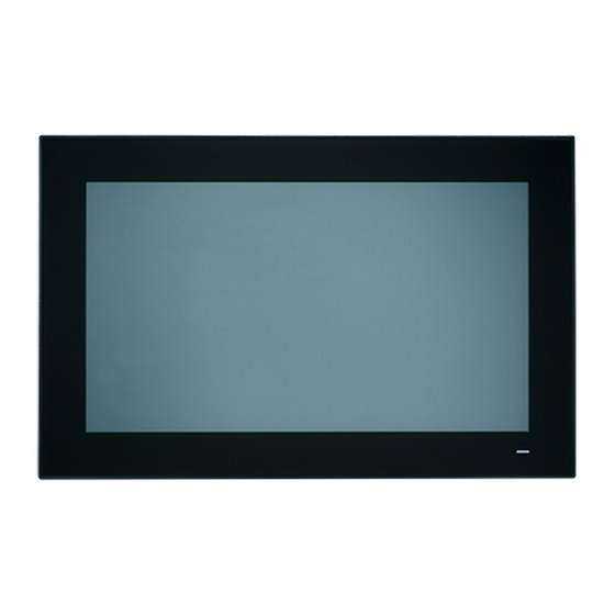
Introduction PPC-3151W/3211W is a new-generation panel PC equipped with a WXGA (1920 x 1080) display, high-performance Intel® Core™ i processor, fanless thermal design, multiple I/O (5 x COM, 5 x USB, and 2 x Gigabit Ethernet), and PCIe/PCI expansion slots for integrating additional fieldbus or proprietary cards according to application requirements. -
Page 13: Rear Panel
Rear Panel The PPC-3151W rear panel features four VESA mount holes (100 x 100 mm), as shown in Figure 1.2. Figure 1.2 PPC-3151W Rear Panel The PPC-3211W rear panel features eight VESA mount holes (100 x 100 mm or 75 x 75 mm), as shown in Figure 1.3. -
Page 14: Dimensions
Figure 1.4 PPC-3151W Dimensions Figure 1.5 PPC-3211W Dimensions Note! Both PPC-3151W and PPC-3211W support VESA 100 x 100 mm or 75 x 75 mm. For mounting, use M4 screws at an 8 mm max. depth and suit- able mounting apparatus to avoid injury. -
Page 15: Specifications
EMC: CE, FCC Class B, BSMI 419.7 x 269 x 59 mm/ 558.4 x 349.8 x 63.8 mm/ Dimensions 16.5 x 10.6 x 2.3 in 22.0 x 13.7 x 2.5 in Weight 5.4 kg/11.9 lb 7.7 kg/17.1 lb PPC-3151W/3211W User Manual... -
Page 16: Ordering Information
PPC-3151W-P75A panel PC with Intel® Core™ i5- PPC-3211W-P75A 7300U processor Power adapter 100 ~ 240 V , 90 96PSA-A90W19OT-3 W, 19V with PFC PPC-WLAN-C1E Wi-Fi module with antenna PPC-ARM-A03 VESA standard arm mount PPC-174T-WL-MTE Wall mount kit PPC-3151W/3211W User Manual... - Page 17 PPC-Stand-A1E Stand kit Optional module (right side instal- lation) 2 x RS-232 or 1 x RS-232 + 98R3P321100 1 x GPIO (TTL, 8 pin programma- ble) 98R3P321110 TPM 2.0 module PPC-3151W/3211W User Manual...
- Page 18 PPC-3151W/3211W User Manual...
-
Page 19: Chapter 2 System Installation & Setup
Chapter System Installation & Setup Quick Installation Guide Installation Procedures Memory Installation HDD Installation M.2 Installation Wireless LAN Installation COM/GPIO Installation TPM Installation Expansion Card Installation AT/ATX Switch Grounding Installation ... -
Page 20: Quick Installation Guide
Power status indicator - Off (S5): orange; On (S0): blue Figure 2.2 Side View 2 x Quick installation clips 2 x Antenna holes 12 x Panel Mount Bracket holes 2 x RS-232 (optional) 1 x CPU cooler 2 x Speakers PPC-3151W/3211W User Manual... -
Page 21: I/O Interfaces
E: 1 x VGA F: 1 x DP G: 2 x COM RS-232 H: 1 x DC power input (9 ~ 32 V) I: 1 x COM RS-422/485 J: 1 x Power button K: 1 x Grounding screw PPC-3151W/3211W User Manual... -
Page 22: Installation Procedures
Connect the female end of the power cable to the DC input socket of the panel Connect the male end of the power cable to the power outlet. Figure 2.4 Connecting the Power Cable 2.2.2 Keyboard and Mouse Connect the keyboard and mouse to the I/O ports of the panel PC. PPC-3151W/3211W User Manual... -
Page 23: Activate Power
The following instructions are provided using the PPC-3211W model for reference: Remove the screws circled in Figure 2.5. Push the tabs circled in red in Figures 2.6 and 2.7 to open the rear cover (Figure 2.8). Figure 2.5 Figure 2.6 Figure 2.7 Figure 2.8 PPC-3151W/3211W User Manual... - Page 24 Attach the CPU heat sink and reinforcement plate after the grease is applied. Figure 2.10 Figure 2.9 Note! The CPU cooler pad surface is isolated via anodization treatment to avoid static electricity (excluding the CPU contact side). PPC-3151W/3211W User Manual...
-
Page 25: Hdd/Ssd Installation
(eight screws if installing two HDDs) (see Figure 2.12 for reference). Replace the HDD bracket and tighten screws to affix in place. Connect the HDD cable to the mainboard (Figure 2.13). Figure 2.11 Figure 2.12 Figure 2.13 PPC-3151W/3211W User Manual... -
Page 26: For Ppc-3151W
Follow the procedures in Section 2.3 to open the rear cover and remove the screws circled in red in Figure 2.14 to retrieve the reinforcement plate. Figure 2.14 Using four screws from the accessory box, attach the HDD/SSD bracket with HDD/SSD onto the reinforcement plate (Figure 2.15). Figure 2.15 PPC-3151W/3211W User Manual... - Page 27 (see Figure 2.16). Figure 2.16 Replace the HDD/SSD bracket and reinforcement plate and use screws to affix it in place. Connect the HDD/SSD cable to the mainboard (Figure 2.17). Figure 2.17 PPC-3151W/3211W User Manual...
-
Page 28: M.2 Installation
Plug the M.2 drive into the mainboard interface. Retrieve the two (M2.5x4) screws from the accessory box to affix the drive in place (Figure 2.19). Replace the rear cover and reinforcement plate. Figure 2.18 Figure 2.19 Figure 2.20 PPC-3151W Reinforcement Plate PPC-3151W/3211W User Manual... -
Page 29: Wireless Lan Installation
Remove the two plugs on the left and right sides of the rear cover (Figure 2.24). Replace the rear cover and install the antenna of the wireless LAN card module (Figure 2.25). Note! For these panel PCs, we recommend the Advantech wireless LAN card module (Part number: PPC-WLAN-C1E). Figure 2.23 Figure 2.24... - Page 30 Figure 2.25 PPC-3151W/3211W User Manual...
-
Page 31: Com/Gpio Installation
CN13 as shown in Figure 2.28. Then replace the reinforcing plate and the rear cover. (If the COM5 cable is connected to CN12, COM5 will support GPIO.) COM4 CN13 CN16 COM5 /GPIO CN12 Figure 2.28 PPC-3151W/3211W User Manual... -
Page 32: Tpm Installation
(see Figure 2.29). Figure 2.29 For PPC-3151W: Connect the cable to the TPM interface. The white label shown in Figure 2.30 corresponds to Pin 1 of the TPM board. The direction of the line is shown below. - Page 33 Align Pin 1 of the TPM board with CN14 on the motherboard. Use screws to attach the TPM board to the reinforcing plate. Figure 2.31 PPC-3151W/3211W User Manual...
-
Page 34: Riser Card Installation
An expansion PCI riser card can be easily installed as shown in Figures 2.34 and 2.35. Note! The maximum dimensions supported for expansion cards is 175 x 106.7 mm/6.88 x 4.2 in. Figure 2.32 Figure 2.33 Figure 2.35 Figure 2.34 PPC-3151W/3211W User Manual... -
Page 35: At/Atx Switch
2.10 AT/ATX Switch The PPC-3151W/3211W panel PC is equipped with a built-in AT/ATX switch for switching between AT and ATX functions without needing to remove the rear cover. Figure 2.36 ATX Mode Figure 2.37 AT Mode PPC-3151W/3211W User Manual... -
Page 36: Grounding Installation
Connect the grounding cable to the grounding screw. Tighten the screw to secure the connection. Figure 2.39 Figure 2.38 Figure 2.40 Figure 2.41 Note! A grounding cable is not provided with the product. Customers will need to purchase this cable separately. PPC-3151W/3211W User Manual... -
Page 37: Hook Installation
Hook Installation Hook Put the machine into the carbinet, and prepare the hook. Install the hook into the hole to hold the machine as shown above Screw Secure the machine by fastening the screws Figure 2.42 Hook Installation PPC-3151W/3211W User Manual... -
Page 38: Wall Mounting
2.13 Wall Mounting The PPC-3151W/3211W panel PC is designed to be easily wall mounted by a single person. To mount the panel PC onto a wall, simply follow the procedures below. Loosen the two screws at the base of the panel PC, as shown in Figure 2.43. - Page 39 Tighten the two screws at the base of the panel PC to complete the installation. Note! For rapid installation, the recommend mount thickness is less than 2 mm/0.079 in. For other situations, the recommended thickness can be a maximum of 6 mm/0.236 in. PPC-3151W/3211W User Manual...
- Page 40 PPC-3151W/3211W User Manual...
-
Page 41: Chapter 3 Jumper Configuration
Chapter Jumper Configuration Jumpers & Connectors External COM Pin Definitions... -
Page 42: Jumpers & Connectors
COM Pin9 Power Select (COM1 & COM2) CN22 Power Button CN24 Power Input CN29 Front LED CN36 COM3 (RS-422/485) AMP1 Amplifier Connector JP1/JP2 Invert Enable/PWM Power Select Panel Power Select Touch Power Select RTC Reset Panel Resolution AT/ATX Select PPC-3151W/3211W User Manual... - Page 43 Picture Invert Enable Power Select (1-2) (2-3) 3.3V Default* Picture Invert PWM Power Select (1-2) (2-3) 3.3V Default* Picture Panel Power Select (1-2) (2-3) 3.3V Default* PPC-3151W/3211W User Manual...
- Page 44 Picture Resistive Touch Power Select (1-2) 3.3VSB Default* (2-3) 3.3V Picture RTC Reset (1-2) Normal* Default* (2-3) CMOS Clear PPC-3151W/3211W User Manual...
- Page 45 COM1/2 RING and Power Select (1-3)/(2-4) P11/P12 COM1/COM2 RI Default* (3-5)/(4-6) P13/P14 COM1/COM2 5V (7-9)/(8-10) P15/P16 COM1/COM2 12V AT/ATX Select 1,2,3 off; 4 on 1920 x 1080 (48 bit) PPC-3211W 1,2 off; 3, 4 on 1920 x 1080 (48 bit) PPC-3151W PPC-3151W/3211W User Manual...
- Page 46 AT/ATX Select ATX Power Default* AT Power CN12 GPIO Name GPIO4 GPIO0 GPIO5 GPIO1 GPIO6 GPIO2 GPIO7 GPIO3 PPC-3151W/3211W User Manual...
-
Page 47: External Com Pin Definitions
COM 1 and COM 2: RS-232 (pin 9 supports 5V/12V output) COM 3: RS-422/485 COM1/COM2 RING or 5V/12V output Pin 9 is configured for RI signals by default. However, it can be configured for 5V/12V output via a jumper. PPC-3151W/3211W User Manual... -
Page 48: Uart Rs-485 Auto-Flow Control
To enable RS-485 auto-flow control, the parity and stop-bit settings must follow one of the configurations below. (1) 8 data bits + 1 parity bit + 1stop bit (2) 8 data bits + 1 parity bit + 2 stop bits (3) 8 data bits + 2 stop bits PPC-3151W/3211W User Manual... -
Page 49: Chapter 4 Software Configuration
Chapter Software Configuration Driver Installation BIOS Setup Utility... -
Page 50: Driver Installation
Driver Installation Before installing software on the panel PC, the corresponding drivers must be installed for full functionality. All drivers can be downloaded from the Advantech website: http://www.advantech.com BIOS Setup Utility 4.2.1 Entering the BIOS When the power is turned on, press <Del> to enter the BIOS setup utility. -
Page 51: Lcd Brightness Adjustment
4.2.2 LCD Brightness Adjustment Select System Agent (SA) Configuration in the Chipset tab. Then select Graphics Configuration. PPC-3151W/3211W User Manual... - Page 52 Select LCD Control. Click Brightness Manual Control to choose between the six brightness levels. PPC-3151W/3211W User Manual...
-
Page 53: Com3 Mode Selection (Rs422/Rs485)
4.2.3 COM3 Mode Selection (RS422/RS485) Select NCT6106D Super IO Configuration in the Advanced tab. Select Serial Port 3 Configuration. PPC-3151W/3211W User Manual... - Page 54 Select Serial Port 3 Mode and then choose between RS422 or RS485 to set the COM3 operation mode. When the COM3 mode is set as RS485, RS485 Auto Flow can be Enabled/Dis- abled. PPC-3151W/3211W User Manual...
-
Page 55: Bios At & Atx Setup
When the COM3 mode is set as RS422/RS485, Serial Port 3 Terminal can be Enabled/Disabled. 4.2.4 BIOS AT & ATX Setup Select PCH-IO Configuration in the Chipset tab. PPC-3151W/3211W User Manual... - Page 56 Select Restore AC Power Loss then set Power On as AT Mode and Power Off as ATX Mode. PPC-3151W/3211W User Manual...
-
Page 57: Wake-On-Lan Or Ring
4.2.5 Wake-on-LAN or Ring Select PCH-IO Configuration in the Chipset tab. Set Wake on By PCIE Wake as Enabled if wake up is via I211 or Ring. PPC-3151W/3211W User Manual... -
Page 58: Raid Installation
Set Wake on LAN Enable as Enabled if wake up is via I219. 4.2.6 RAID Installation (This is only available for PPC-3211W.) Select PCH-IO Configuration in the Chipset tab. PPC-3151W/3211W User Manual... - Page 59 Select SATA AND RST Configuration. Select SATA Mode Selection -> Intel RST Premium with Intel Optane Sys- tem Acceleration. Save and restart the BIOS setup utility. PPC-3151W/3211W User Manual...
- Page 60 Select Intel(R) Rapid Storage Technology in the Advanced tab. Select Create RAID Volume to enter the RAID settings page. PPC-3151W/3211W User Manual...
- Page 61 Configure Name and RAID Level and select the corresponding storage device. PPC-3151W/3211W User Manual...
- Page 62 Select Create Volume. Save and exit the BIOS setup utility. Allow the system to boot from the installation device to initiate standard installation procedures. PPC-3151W/3211W User Manual...
-
Page 63: Tpm Settings
4.2.7 TPM Settings Select Trusted Computing in the Advanced tab. Change Security Device Support to Enabled. Save and restart the BIOS setup utility. PPC-3151W/3211W User Manual... - Page 64 Upon reentering the BIOS setup utility, the device will be listed and operational. PPC-3151W/3211W User Manual...
- Page 65 PPC-3151W/3211W User Manual...
- Page 66 No part of this publication may be reproduced in any form or by any means, such as electronically, by photocopying, recording, or otherwise, without prior written permission from the publisher. All brand and product names are trademarks or registered trademarks of their respective companies. © Advantech Co., Ltd. 2020...
Need help?
Do you have a question about the PPC-3151W and is the answer not in the manual?
Questions and answers