
Related Manuals for Advantech PPC-3150SW


Summary of Contents for Advantech PPC-3150SW
- Page 1 User Manual PPC-3150SW PPC-3180SW PPC-324W-PN4 15.6"/18.5"/23.8" Panel PC with TFT LCD and Intel® Pentium® N4200 Processor...
- Page 2 No part of this manual may be reproduced, copied, translated, or transmitted in any form or by any means without the prior written permission of Advantech Co., Ltd. The information provided in this manual is intended to be accurate and reliable.
- Page 3 (ESD) or electromagnetic interference (EMI) leakage, we strongly recommend using CE-compliant industrial enclosure products. Technical Support and Assistance Visit the Advantech website at http://support.advantech.com to obtain the latest product information. Contact your distributor, sales representative, or Advantech's customer service center for technical support if you need additional assistance. Please have the following information ready before calling: –...
- Page 4 N’ouvrez jamais l’appareil. Pour des raisons de sécurité, l’appareil ne doit être ouvert que par un technician qualifié. If one of the following occurs, have the equipment checked by service person- nel: Si l’un des cas suivants se produit, demandez aide à un technicien qualifié: PPC-3150SW/3180SW/324W-PN4 User Manual...
- Page 5 AVERTISSEMENT: Ces instructions sont fournies conformément aux normes IEC 704-1. Advantech decline toute responsabilité quant à la précision de toute déclaration contenue dans le présent document. CAUTION: This product is not intended for use by children and is not suitable for use in locations where children are likely to be present (this product is not a toy).
- Page 6 ATTENTION: Ce produit n’est pas un jouet et devrait être gardé hors de la portée des enfants. PPC-3150SW/3180SW/324W-PN4 User Manual...
- Page 7 The power is fit for areas with an altitude of below 5,000 M. Battery Information Batteries, battery packs, and accumulators should not be disposed of as unsorted household waste. Please use the public collection system to return, recycle, or treat them in compliance with the local regulations. 。 vii PPC-3150SW/3180SW/324W-PN4 User Manual...
- Page 8 PPC-3150SW/3180SW/324W-PN4 User Manual viii...
-
Page 9: Table Of Contents
Figure 1.1 Front Panel ..............2 Rear Panel ....................3 Figure 1.2 Rear Panel..............3 Dimensions ....................4 Figure 1.3 PPC-3150SW-PN4A Dimensions....... 4 Figure 1.4 PPC-3180SW-PN4A Dimensions....... 4 Figure 1.5 PPC-324W-PN40A Dimensions ......... 4 Specifications .................... 5 Ordering Information ................. 6... - Page 10 4.2.3 COM2 Mode Selection (RS-232/422/485) ........33 4.2.4 OS Selection................35 4.2.5 BIOS AT/ATX Setup ..............36 4.2.6 Wake-on-LAN ................38 4.2.7 Wake-on-Ring................39 Appendix A Watchdog Timer Programming ..41 Watchdog Timer Programming Example ..........42 PPC-3150SW/3180SW/324W-PN4 User Manual...
-
Page 11: Chapter 1 General Information
Chapter General Information Introduction Specifications Dimensions... -
Page 12: Introduction
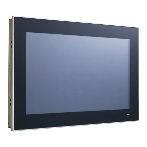
IP65-rated front panel Front Panel The PPC-3150SW/3180SW/324W-PN4 front panel is a true-flat color TFT LCD with multi-touch projected capacitive touch control. Additionally, the front panel is IP65 rated for protection from dust and water ingress. Note! Figure 1.1 shows the PPC-3150SW-PN4A model. The PPC-3150SW/ 3180SW/324W-PN4 models all follow the same design. -
Page 13: Rear Panel
Rear Panel The PPC-3150SW/3180SW/324W-PN4 rear panel features four VESA mount holes (75 x 75 mm) as shown in Figure 1.2. Speaker Speaker Figure 1.2 Rear Panel VESA Screw Specifications Screw Type: M4 Screw Depth:12 mm max. Screw Quantity: 4 3 PPC-3150SW/3180SW/324W-PN4 User Manual... -
Page 14: Dimensions
Dimensions 410.96 419.70 75.00 Cutout dimensions: 413 x 262 mm Figure 1.3 PPC-3150SW-PN4A Dimensions 477.72 488.00 75.00 Cutout dimensions: 479.3 x 300.3 mm Figure 1.4 PPC-3180SW-PN4A Dimensions Figure 1.5 PPC-324W-PN40A Dimensions PPC-3150SW/3180SW/324W-PN4 User Manual... -
Page 15: Specifications
488 x 309 x 58.45 mm 595.9 x 374.1 x 58.4 mm Dimensions (16.52 x 10.59 x 2.3 in) (19.21 x 12.16 x 2.3 in) (23.5" x 14.7" x 2.3") Weight 4.7 kg (10.36 lb) 5.4 kg (11.90 lb) 8.2kg (18.08lb) 5 PPC-3150SW/3180SW/324W-PN4 User Manual... -
Page 16: Ordering Information
Intel® Pentium® APL N4200 PPC-3150SW-PN4A PPC-3180SW-PN4A Fanless 15.6"/18.5"/23.8" panel PPC-324W-PN40A Power adapter 100 ~ 240 V 96PSA-A90W19OT-3 90 W, 19V with PFC PPC-WLAN-C1E Wi-Fi module with antenna PPC-ARM-A03 VESA arm mount (standard) PPC-174T-WL-MTE Wall mount kit PPC-Stand-A1E Stand kit PPC-3150SW/3180SW/324W-PN4 User Manual... -
Page 17: Chapter 2 System Installation And Setup
Chapter System Installation and Setup Quick System Tour Memory Card Installation HDD Installation mSATA Installation Wireless LAN Card Installation System Mounting... -
Page 18: Quick System Tour
Before setting up the panel PC, take a moment to identify the locations of the device controls, drives, connectors, and ports (as shown in Figure 2.3). When placed upright, the PPC-3150SW/3180SW/324W-PN4 front panel should appear as shown in Figure 2.1. -
Page 19: Installation Procedures
Install a SATA HDD or mSATA storage Install a memory card Install a wireless LAN module Mount the panel PC 2.2.1 HDD Installation Loosen and remove the 9 retention screws on the rear cover. Remove the rear cover. 9 PPC-3150SW/3180SW/324W-PN4 User Manual... - Page 20 Loosen and remove the 4 retention screws on the HDD bracket. Remove the HDD bracket. Install a SATA HDD and affix in place using 4 retention screws Close the HDD cover and affix in place using 4 retention screws PPC-3150SW/3180SW/324W-PN4 User Manual...
-
Page 21: Msata Installation
Connect the SATA cable to the motherboard. 2.2.2 mSATA Installation Insert an mSATA card into the mSATA socket. Secure the mSATA module using 2 retention screws provided in the accessory box. 11 PPC-3150SW/3180SW/324W-PN4 User Manual... -
Page 22: Memory Card Installation
2.2.3 Memory Card Installation Insert the memory card into the slot highlighted by the red box in the image below. Then install the memory and CPU thermal pads provided in the acces- sory box. PPC-3150SW/3180SW/324W-PN4 User Manual... -
Page 23: Wireless Lan Module Installation
2.2.4.2 Half-Size Mini PCIe Card Installation Retrieve the hexagonal screw provided in the accessory box. Align the screw with the notch on the printed circuit board and secure in place. 13 PPC-3150SW/3180SW/324W-PN4 User Manual... - Page 24 Insert the half-size mini PCIe card into the socket at an angle. Secure the card in place using a screw from the accessory box. Connect the antenna cables and affix them to the brackets. Take note of the cable routing. Remove the two rubber plugs on the rear cover. PPC-3150SW/3180SW/324W-PN4 User Manual...
-
Page 25: System Mounting
Warning! More than one person should participate in mounting the panel PC to prevent accidental damage to the panel or personal injury. Le comité constate qu'el-nasr mounting, plus d'une personne installation to prevent the cadre accidental damage to personal injury. The PPC-3150SW/3180SW/324W-PN4 panel PC supports various mounting options. Wall mounting ... - Page 26 Align the wall mount bracket attached to the panel PC with the wall mount plate on the wall and slide the panel PC downwards to hang the bracket on the mount plate (Figure 2.6). Figure 2.6 Wall Mounting PPC-3150SW/3180SW/324W-PN4 User Manual...
-
Page 27: Panel Mounting
To mount the flat bezel panel PC into a panel, follow the steps below. Prepare a panel cutout that corresponds to the device size. PPC-3150SW: 413 x 262 mm / 16.25 x 10.31 in PPC-3180SW: 479.30 x 300.30mm / 18.87 x 11.82 in PPC-324W-PN4: 586.5 x 364.8 mm / 23.09 x 14.36 in... - Page 28 Tighten the screws in the hook brackets to secure the panel PC in place. Figure 2.10 Fastening Hook Bracket Screws Figure 2.11 Panel Mount Rear View PPC-3150SW/3180SW/324W-PN4 User Manual...
-
Page 29: Arm Mounting
2.3.3 Arm Mounting PPC-3150SW/3180SW/324W-PN4 can be mounted on a VESA-compliant arm mount with a 100-mm pad. To affix the panel PC to an arm mount, follow the steps outlined below. Refer to the mounting arm’s installation instructions to correctly mount the arm onto the surface as a base. -
Page 30: Stand Mounting
Remove the four original screws at the rear of the machine. Use four M4 x 8L screws to affix the VESA bracket to the panel PC. Users can choose between a 75 x 75 mm VESA mount according to their requirements. Figure 2.13 VESA Mount Screw Holes PPC-3150SW/3180SW/324W-PN4 User Manual... - Page 31 Use four M4 x 8L screws to secure the base plate to the mount stand. Figure 2.14 Securing the VESA Mount Base Use four M4 x 6L screws to secure the mount stand to the VESA mount bracket. Figure 2.15 Securing the VESA Mount Bracket 21 PPC-3150SW/3180SW/324W-PN4 User Manual...
- Page 32 Use one M4 x 5L screw to attach the stand mount hinge cover. Figure 2.16 Stand Mount Hinge Cover Figure 2.17 Completed Stand Mount PPC-3150SW/3180SW/324W-PN4 User Manual...
-
Page 33: Chapter 3 Jumper Setting
Chapter Jumper Setting Motherboard Layout Jumpers and Connectors External COM Ports and Pin Definitions... -
Page 34: Motherboard Layout
Motherboard Layout The PPC-3150SW/3180SW/324W-PN4 motherboard features internal peripheral connectors that can be accessed when the motherboard is outside of the chassis. Figure 3.1 shows the locations of the internal peripheral connectors on the mother- board. Figure 3.1 Motherboard Layout Diagram... -
Page 35: Jumpers And Connectors
(1~2) (2~3) 3.3V (default) Icon Backlight PWM Power Selection (1~2) (2~3) 3.3V (default) Icon Touch Power Selection (1~2) Closed 3.3VSB (1~2) Open Resistive touch disabled (default) Icon ATX/AT Selection (1~2) AT power (2~3) ATX power (default) 25 PPC-3150SW/3180SW/324W-PN4 User Manual... - Page 36 COM1 5V (4~5) COM1 12V Icon Panel Resolution 1,2,3 ON; 4 OFF 1366 x 768 (24 bit) for PPC-3180SW 1,2,3 OFF; 4 ON 1366 x 768 (24 bit) for PPC-3150SW 1, 2 OFF; 3,4 ON 1920x1080(48bit) for PPC-324W-PN4 PPC-3150SW/3180SW/324W-PN4 User Manual...
-
Page 37: External Com Port Pin Definition
External COM Port Pin Definition 3.3.1 COM1: RS-232; COM2: RS-232/422/485 COM1 COM2 COM2_422_485_TX- COM2_422_485_TX+ COM2_422_RX+ COM2_422_RX- Ring or 5V/12V output Ring 27 PPC-3150SW/3180SW/324W-PN4 User Manual... - Page 38 PPC-3150SW/3180SW/324W-PN4 User Manual...
-
Page 39: Software Setup
Chapter Software Setup Driver Installation BIOS Setup Program... -
Page 40: Driver Installation
Driver Installation Before installing software on the panel PC, install the corresponding drivers to ensure full functionality. All drivers can be downloaded from the Advantech website at http://www.advantech.com. BIOS Setup Program 4.2.1 Entering the BIOS Utility During system bootup, press the <Del> button to enter the BIOS setup utility. -
Page 41: Lcd Brightness Settings
4.2.2 LCD Brightness Settings Select the “North Bridge” item in the “Chipset” tab. Then select “LCD Control”. 31 PPC-3150SW/3180SW/324W-PN4 User Manual... - Page 42 Select “Brightness Mode Control”. There are six brightness levels available.Select the level most suitable for your application needs. PPC-3150SW/3180SW/324W-PN4 User Manual...
-
Page 43: Com2 Mode Selection (Rs-232/422/485)
4.2.3 COM2 Mode Selection (RS-232/422/485) Select the “NCT6116D Super IO Configuration” option in the “Advanced” tab. Select “Serial Port 2 Configuration”. 33 PPC-3150SW/3180SW/324W-PN4 User Manual... - Page 44 Navigate to the “Serial Port 2 Mode” item and double click to set the COM2 operation mode as [RS-422] or [RS-485]. When COM2 Mode is set as RS-485, the “RS-485 Auto Flow” item can be con- figured as [enabled] or [disabled] PPC-3150SW/3180SW/324W-PN4 User Manual...
-
Page 45: Os Selection
When COM3 Mode is set as RS-485, the “Serial Port3 Terminal” can be config- ured as [enabled] or [disabled] 4.2.4 OS Selection Select the “South Bridge” item in the “Chipset” tab. 35 PPC-3150SW/3180SW/324W-PN4 User Manual... -
Page 46: Bios At/Atx Setup
The system supports different OS [Windows/Android/Intel Linux]. Navigate to the “OS Selection” item to set the system OS. 4.2.5 BIOS AT/ATX Setup Select the “South Cluster Configuration” item in the “Chipset” tab. PPC-3150SW/3180SW/324W-PN4 User Manual... - Page 47 Select the “Miscellaneous Configuration” item. Configure the “Restore AC Power Loss” item as “Power On” when in “AT Mode” and as “Power Off” for “ATX Mode”. 37 PPC-3150SW/3180SW/324W-PN4 User Manual...
-
Page 48: Wake-On-Lan
4.2.6 Wake-on-LAN Select the “South Cluster Configuration” item in the “Chipset” tab. Select the “Miscellaneous Configuration” item. PPC-3150SW/3180SW/324W-PN4 User Manual... -
Page 49: Wake-On-Ring
Set “Wake-on-PCIE” as “enabled”. 4.2.7 Wake-on-Ring Select the “NCT6106D Super IO Configuration” item in the “Advanced” tab. 39 PPC-3150SW/3180SW/324W-PN4 User Manual... - Page 50 Set “Wake-on-Ring” to “enabled”. PPC-3150SW/3180SW/324W-PN4 User Manual...
-
Page 51: Watchdog Timer Programming
Appendix Watchdog Timer Programming... -
Page 52: Watchdog Timer Programming Example
MOV DX, 2FH MOV AL, 00H; bit 0: 0 = pulse mode, 1 = level mode; bit 3: 0 = second mode, 1 = minute mode OUT DX, AL; set second mode, default value ;----------------------------------------------------------------------------- ;Set WDT timeout value PPC-3150SW/3180SW/324W-PN4 User Manual... - Page 53 OUT DX, AL MOV DX, 2FH MOV AL, 05H OUT DX, AL; set timeout value as 5s; 00 = timeout disabled ;----------------------------------------------- ; Exit the Extended Function Mode ;---------------------------------------------- MOV DX, 2EH MOV AL, AAH OUT DX, AL 43 PPC-3150SW/3180SW/324W-PN4 User Manual...
- Page 54 No part of this publication may be reproduced in any form or by any means, such as electronically, by photocopying, recording, or otherwise, without prior written permission from the publisher. All brand and product names are trademarks or registered trademarks of their respective companies. © Advantech Co., Ltd. 2020...
Need help?
Do you have a question about the PPC-3150SW and is the answer not in the manual?
Questions and answers