Beckhoff EL1904 Operating Instructions Manual
Twinsafe terminal with 4 digital fail-safe inputs
Hide thumbs
Also See for EL1904:
- Operating instructions manual (57 pages) ,
- Operating instructions manual (67 pages)

Related Manuals for Beckhoff EL1904


Summary of Contents for Beckhoff EL1904
- Page 1 Operating Instructions for EL1904 TwinSAFE Terminal with 4 digital fail-safe inputs Version: 2.1.1 Date: 2017-02-07...
-
Page 3: Table Of Contents
2.2.1 The I/O construction kit is extended safely .............. 12 2.2.2 Safety concept ......................... 12 2.2.3 EL1904, EL2904 - Bus Terminals with 4 fail-safe inputs or outputs ........ 13 2.2.4 EL6900 - TwinSAFE logic terminal .................. 13 2.2.5 The fail-safe principle (Fail Stop) .................. 13 3 Product description.......................... 14... - Page 4 Table of contents 4.5.1 Diagnostic LEDs....................... 39 4.5.2 Diagnostic objects ...................... 40 Maintenance .......................... 41 Service life ............................ 42 Decommissioning ......................... 42 5 Appendix .............................. 43 Support and Service ........................ 43 Certificates............................ 44 Version: 2.1.1 EL1904...
-
Page 5: Foreword
Product features Only the product features specified in the current user documentation are valid. Further information given on the product pages of the Beckhoff homepage, in emails or in other publications is not authoritative. Disclaimer The documentation has been prepared with care. The products described are subject to cyclical revision. For that reason the documentation is not in every case checked for consistency with performance data, standards or other characteristics. -
Page 6: Safety Instructions
Offenders will be held liable for the payment of damages. All rights reserved in the event of the grant of a patent, utility model or design. Delivery conditions In addition, the general delivery conditions of the company Beckhoff Automation GmbH & Co. KG apply. Safety instructions 1.2.1... -
Page 7: Description Of Safety Symbols
Damage to the environment or devices Failure to follow the instructions associated with this symbol can lead to damage to the en- vironment or equipment. Attention Tip or pointer This symbol indicates information that contributes to better understanding. Note EL1904 Version: 2.1.1... -
Page 8: Documentation Issue Status
• Description of date code extended 1.3.1 • Document origin added 1.3.0 • Clock output currents in the technical data amended • Block diagram for EL1904 added 1.2.1 • Reference to EN 60068-2-29 removed 1.2.0 • ATEX notes amended • Installation position / minimum distances extended •... -
Page 9: System Description
System description The Beckhoff Bus Terminal system The Beckhoff Bus Terminal system is used for decentralized connection of sensors and actuators to a control system. The Beckhoff Bus Terminal system components are mainly used in industrial automation and building management applications. In its minimum configuration, a bus station consists of a Bus Coupler or a Bus Terminal Controller and Bus Terminals connected to it. -
Page 10: Bus Coupler
Fig. 2: Bus Coupler (EtherCAT) Connection technology Bus Coupler Wiring spring-loaded system Connection cross-section 0.08 mm² ... 2.5 mm², stranded wire, solid wire Fieldbus connection depending on fieldbus Power contacts 3 spring contacts Current load 10 A Rated voltage 24 V Version: 2.1.1 EL1904... -
Page 11: Bus Terminals
The power feed terminals play no part in the control of the terminals, and can be inserted at any locations within the terminal strip. EL1904 Version: 2.1.1... -
Page 12: Twinsafe
2.2.1 The I/O construction kit is extended safely With the TwinSAFE Terminals, Beckhoff offers the option of simply expanding the proven Bus Terminal system, and to transfer the complete cabling for the safety circuit into the already existing fieldbus cable. -
Page 13: El1904, El2904 - Bus Terminals With 4 Fail-Safe Inputs Or Outputs
EL1904, EL2904 - Bus Terminals with 4 fail-safe inputs or outputs The EL1904 and EL2904 Bus Terminals enable connection of common safety sensors and actuators. They are operated with the EL6900 TwinSAFE logic terminal. The TwinSAFE logic terminal is the link unit between the TwinSAFE input and output terminals. -
Page 14: Product Description
. The Bus Terminal has 4 fail-safe inputs. With two-channel connection, the EL1904 meets the requirements of IEC 61508:2010 SIL 3, DIN EN ISO 13849-1:2006 (Cat 4, PL e), NRTL, UL508, UL1998 and UL991. The TwinSAFE terminal has the typical design of an EtherCAT terminal. - Page 15 Note The following TwinSAFE components have been developed for these tasks: • The EL1904 is an EtherCAT Terminal with 4 digital fail-safe inputs. • The EL2904 is an EtherCAT Terminal with 4 digital fail-safe outputs. • The EL6900 is an EtherCAT Terminal with integrated TwinSAFE logic.
-
Page 16: Technical Data
10 mA, max. 15 mA Input process image 6 bytes Output process image 6 bytes EL1904 supply voltage (PELV) 24 V (–15% / +20%) Signal voltage "0" inputs -3 V to 5 V (EN 61131-2, type 3) see chapter Characteristic curve of the inputs [} 17] Signal voltage "1"... -
Page 17: Safety Parameters
Element classification Type B 1. Special proof tests are not required during the entire service life of the EL1904 EtherCAT terminal. 2. Classification according to IEC 61508-2:2010 (chapter 7.4.4.1.2 and 7.4.4.1.3) The EL1904 EtherCAT Terminal can be used for safety-related applications within the meaning of IEC 61508:2010 up to SIL3 and EN ISO 13849-1 up to PL e (Cat4). -
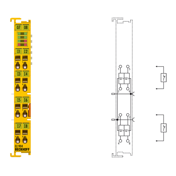
Page 18: Dimensions
Depth: 68 mm Block diagram of the EL1904 Fig. 7: Block diagram of the EL1904 The block diagram shows the basic configuration of a channel in the EL1904. The part with a red border is present four times in the terminal. Version: 2.1.1... -
Page 19: Operation
Bring the bus system into a safe, de-energized state before starting installation, disassem- bly or wiring of the devices! DANGER 4.2.3.1 Control cabinet / terminal box The TwinSAFE terminals must be installed in a control cabinet or terminal box with IP54 protection class according to IEC 60529 as a minimum. EL1904 Version: 2.1.1... -
Page 20: Fig. 8 Installation Position And Minimum Distances
Fig. 8: Installation position and minimum distances In order to ensure optimum convection cooling, the distances to neighboring devices and to control cabinet walls must not be smaller than those shown in the diagram. Version: 2.1.1 EL1904... -
Page 21: Fig. 9 Example Configuration For Temperature Measurement
The key parameter is always the maximum permitted internally measured temperature of 95°C, above which the TwinSAFE terminals switch to safe state and report an error. The in- ternal temperature can be read from the TwinSAFE components via CoE (see chapter Di- agnose). EL1904 Version: 2.1.1... -
Page 22: Fig. 10 Installation On The Mounting Rail
For fastening mounting rails with a height of 7.5 mm under the terminals and couplers, use flat fastening compo- nents such as countersunk head screws or blind rivets. Version: 2.1.1 EL1904... -
Page 23: Electrical Installation
(e.g. analog Bus Terminals or digital 4- Note channel Bus Terminals) do not or not fully loop through the power contacts. Power Feed Terminals (EL91xx, EL92xx) interrupt the power contacts and thus represent the start of a new supply rail. EL1904 Version: 2.1.1... -
Page 24: Fig. 12 Pe Power Contact
The PE power contact must not be used for other potentials! DANGER 4.2.4.2 Overvoltage protection If protection against overvoltage is necessary in your plant, provide a surge filter for the voltage supply to the Bus Terminal blocks and the TwinSAFE terminals. Version: 2.1.1 EL1904... -
Page 25: Fig. 13 Connection Of A Cable To A Terminal Point
2. The wire can now be inserted into the round terminal opening without any force. 3. The terminal closes automatically when the pressure is released, holding the wire safely and perma- nently. Wire cross section 0,08 ... 2.5 mm Strip length 8 ... 9 mm EL1904 Version: 2.1.1... -
Page 26: Fig. 14 El1904 Pin Assignment
Operation 4.2.4.4 EL1904 pin assignment Fig. 14: EL1904 pin assignment Terminal point Input Signal Input 1+ Input 1- Input 3+ Input 3- Input 2+ Input 2- Input 4+ Input 4- Configurable inputs The inputs 1 to 4 can be occupied as you want with normally closed contacts or normally open contacts. -
Page 27: Fig. 15 Permitted Cable Length
When connecting a single switching contact via its own continuous cabling (or via a non-metallic sheathed cable), the maximum permitted cable length is 100 m. The use of contact points, connectors or additional switching contacts in the cabling reduces the maximum propagation. Cable routing Fig. 16: Cable routing EL1904 Version: 2.1.1... -
Page 28: Fig. 17 Typical Course Of Test Pulses Of The Inputs
The times between the test pulses of different channels vary, thus allowing better diagnostic detection. Fig. 17: Typical course of test pulses of the inputs If self-testing sensors are to be used on the safe inputs, please refer to chapter Configuration for light barriers, light grids, light curtains etc [} 37]. Version: 2.1.1 EL1904... -
Page 29: Twinsafe Reaction Times
Reaction time of the sensor until the signal is provided at the interface. Typically supplied by the sensor manufacturer. RTInput Reaction time of the safe input, such as EL1904 or EP1908. This time can be found in the technical data. In the case of the EL1904 it is 4 ms. RTComm Reaction time of the communication This is typically 3x the EtherCAT cycle time, because new data can only be sent in a new Safety-over-EtherCAT telegram. -
Page 30: Tested El1904 Devices
4.2.6 Tested EL1904 devices The following list contains devices that were tested together with the EL1904 TwinSAFE terminal. The results only apply for the current device hardware version at the time of testing. The tests were carried out in a laboratory environment. Modifications of these products cannot be considered here. If you are unsure please test the hardware together with the TwinSAFE terminal. -
Page 31: Operation In Potentially Explosive Atmospheres (Atex)
80°C at the wire branching points, then cables must be selected whose temperature data correspond to the actual measured temperature values! Observe the permissible ambient temperature range of 0 to 55 °C when using Beckhoff fieldbus components in potentially explosive atmospheres! -
Page 32: Identification
Operation 4.3.2 Identification Beckhoff fieldbus components that are certified for use in potentially explosive atmospheres bear one of the following markings: II 3 G Ex nA II T4 KEMA 10ATEX0075 X Ta: 0 - 55°C II 3 G Ex nA nC IIC T4 KEMA 10ATEX0075 X Ta: 0 - 55°C... -
Page 33: Inserting A Bus Terminal
Inserting a Bus Terminal See TwinCAT automation software documentation. 4.4.3 Inserting an EL1904 An EL1904 is inserted in the same way as any other Beckhoff Bus Terminal. In the list open Safety Terminals (ELx9xx) and select the EL1904. Fig. 20: Inserting an EL1904 EL1904... -
Page 34: Address Settings On Twinsafe Terminals With 65535 Possible Addresses
Fig. 21: Address settings on TwinSAFE terminals with 65535 possible addresses Set the TwinSAFE address for the terminal using the two dip switches (with 8 setting options) on the left- hand side of the EL1904 TwinSAFE terminal. TwinSAFE addresses between 1 and 65535 are available. DIP switches... -
Page 35: Entering A Twinsafe Address And Parameters In The System Manager
The TwinSAFE address set at the DIP switch must also be entered in tab FSoE (under FSoE address) under the EL1904. Fig. 22: Entering the FSoE address The EL1904 parameters are set under the respective TwinSAFE connection in the Connection and Parameter tabs. EL1904... -
Page 36: Fig. 23 Setting The Connection Of The Twinsafe Connection
Operation Fig. 23: Setting the connection of the TwinSAFE connection Fig. 24: Setting the parameters of the TwinSAFE connection Version: 2.1.1 EL1904... - Page 37 4.4.5.1 EL1904 configuration for light barriers, light grids, light curtains etc. The EL1904 also supports direct connection of contact-free protective devices with two self-testing outputs such as light barriers, light grids, light curtains, laser scanners, etc. Sensors with self-testing outputs! Only sensors with self-testing outputs and a maximum sensor self-test duration of 350 µs...
-
Page 38: Fig. 25 Maximum Permissible Sensor Self-Test Duration Of 350 Μs
The EL1904 also supports direct connection of safety switching mats. Parameter To connect these switching mats please set the following parameters for the EL1904 in the TwinCAT System Manager: Connect the two sensor signals either to channels 1 and 2 or channels 3 and 4 and activate short cut channel x/y is no module fault for the two inputs used under parameter Logic for channel x and y. -
Page 39: Diagnostics
If the Diag 3 LED is lit, the Diag 4 LED indicates internal terminal errors. Flashing Codes In the case of such an error, the Diag 4 LED on the EL1904 displays flashing codes that describe the error in more detail. -
Page 40: Diagnostic Objects
If another flashing code is displayed, this means that there is an internal terminal error that has stopped the terminal. In this case the terminal must be checked by Beckhoff Automation GmbH & Co. KG. Note the flashing codes and return the terminal Note the flashing code displayed and include this information with the terminal when you return it. -
Page 41: Maintenance
If the TwinSAFE component was subjected to unacceptable soiling it may no longer be operated! Have soiled terminals checked! Cleaning of the TwinSAFE component by the user is not permitted! Please send soiled terminals to the manufacturer for inspection and cleaning! WARNING EL1904 Version: 2.1.1... -
Page 42: Service Life
• Housing components (polycarbonate, polyamide (PA6.6)) are suitable for plastic recycling. • Metal parts can be sent for metal recycling. • Electronic parts such as disk drives and circuit boards must be disposed of in accordance with national electronics scrap regulations. Version: 2.1.1 EL1904... -
Page 43: Appendix
Beckhoff's branch offices and representatives Please contact your Beckhoff branch office or representative for local support and service on Beckhoff products! The addresses of Beckhoff's branch offices and representatives round the world can be found on her internet pages: http://www.beckhoff.com You will also find further documentation for Beckhoff components there. -
Page 44: Certificates
Appendix Certificates Version: 2.1.1 EL1904... - Page 45 Appendix EL1904 Version: 2.1.1...
- Page 46 Slot and key system and screwless (spring-loaded) connection system........Fig. 2 Bus Coupler (EtherCAT)......................Fig. 3 TwinSAFE Terminals (EtherCAT)....................Fig. 4 EL1904 – TwinSAFE terminal with 4 digital fail-safe inputs............Fig. 5 Characteristic curve of the inputs ....................Fig. 6 Dimensions of the EL1904......................Fig. 7 Block diagram of the EL1904.......................
Need help?
Do you have a question about the EL1904 and is the answer not in the manual?
Questions and answers