Sign In
Upload
Download
Table of Contents
Contents
Add to my manuals
Delete from my manuals
Share
URL of this page:
HTML Link:
Bookmark this page
Add
Manual will be automatically added to "My Manuals"
Print this page
×
Bookmark added
×
Added to my manuals
Manuals
Brands
Beckhoff Manuals
Touch terminals
EL1258
Documentation
Beckhoff EL1258 Documentation
8 channel digital input/output terminal with time stamp
Hide thumbs
1
2
3
4
5
6
7
8
9
10
11
12
13
14
15
16
17
18
19
20
21
22
23
24
25
26
27
28
29
30
31
32
33
34
35
36
37
38
39
40
41
42
43
44
45
46
47
48
49
50
51
52
53
54
55
56
57
58
59
60
61
62
63
64
65
66
67
68
69
70
71
72
73
74
75
76
77
78
79
80
81
82
83
84
85
86
87
88
89
90
91
92
93
94
95
96
97
98
99
100
101
102
103
104
105
106
107
108
109
110
111
112
113
114
115
116
117
118
119
120
121
122
123
124
125
126
127
128
129
130
131
132
133
134
135
136
137
138
139
140
141
142
143
144
145
146
147
148
149
150
151
152
153
154
155
156
157
158
159
160
161
162
163
164
165
166
167
168
169
170
171
172
173
174
175
176
177
178
179
180
181
182
183
184
185
186
187
188
189
190
191
192
193
194
195
196
197
198
199
200
201
202
203
204
205
206
207
208
209
210
211
212
213
214
215
216
217
218
219
220
221
222
223
224
225
226
227
228
229
230
231
232
233
234
235
236
237
238
239
240
241
242
243
244
245
246
247
248
249
250
251
252
253
254
255
256
257
258
259
260
261
262
263
264
265
266
267
268
269
270
271
272
273
274
275
276
277
278
279
280
281
282
283
284
285
286
287
288
289
290
291
292
293
294
295
296
297
298
299
300
301
302
303
304
305
306
307
308
309
310
311
page
of
311
Go
/
311
Contents
Table of Contents
Bookmarks
Table of Contents
Table of Contents
Product Overview - 8 Channel Digital Input/Output Terminals
2 Foreword
Notes on the Documentation
Safety Instructions
Documentation Issue Status
Version Identification of Ethercat Devices
Fig. 1 EL5021 el Terminal, Standard IP20 IO Device with Batch Number and Revision ID (Since 2014/01)
Fig. 2 EK1100 Ethercat Coupler, Standard IP20 IO Device with Batch Number
Fig. 3 CU2016 Switch with Batch Number
Fig. 4 EL3202-0020 with Batch Numbers 26131006 and Unique ID-Number 204418
Fig. 5 EP1258-00001 IP67 Ethercat Box with Batch Number 22090101 and Unique Serial Number 158102
Fig. 6 EP1908-0002 IP67 Ethercat Safety Box with Batch Number 071201FF and Unique Serial Number 00346070
Fig. 7 EL2904 IP20 Safety Terminal with Batch Number/Date Code 50110302 and Unique Serial Num- Ber 00331701
Fig. 8 ELM3604-0002 Terminal with ID Number (QR Code) 100001051 and Unique Serial Number 44160201
3 Product Overview
El1258, El1259, El2258
Introduction
Technical Data
Technology
Fig. 9 EL1258
Fig. 12 Query of Input Channel Information, Standard
Fig. 13 Query of Input Channel Information, Oversampling
Fig. 14 Query of Input Channel Information, with Timestamp
Fig. 15 Output of Output Channel Information, Standard
Fig. 16 Output of Output Channel Information, Oversampling
Fig. 17 Output of Output Channel Information, with Timestamp
Fig. 18 Query of Input Channel Information, with Multi-Timestamp
Start
Fig. 19 Output of Output Channel Information, with Multi-Timestamp
4 Basics Communication
Ethercat Basics
Ethercat Cabling - Wire-Bound
General Notes for Setting the Watchdog
Fig. 20 System Manager Current Calculation
Fig. 21 Ethercat Tab -> Advanced Settings -> Behavior -> Watchdog
Ethercat State Machine
Fig. 22 States of the Ethercat State Machine
Coe Interface
Fig. 23 "Coe Online " Tab
Fig. 24 Startup List in the Twincat System Manager
Fig. 25 Offline List
Fig. 26 Online List
Distributed Clock
5 Mounting and Wiring
Instructions for ESD Protection
Installation on Mounting Rails
Fig. 27 Spring Contacts of the Beckhoff I/O Components
Fig. 28 Attaching on Mounting Rail
Fig. 29 Disassembling of Terminal
Fig. 30 Power Contact on Left Side
Installation Instructions for Enhanced Mechanical Load Capacity
Connection
Connection System
Fig. 31 Standard Wiring
Fig. 32 Pluggable Wiring
Wiring
Fig. 34 Connecting a Cable on a Terminal Point
Shielding
Installation Positions
Fig. 33 High Density Terminals
Fig. 35 Recommended Distances for Standard Installation Position
Fig. 36 Other Installation Positions
Mounting of Passive Terminals
UL Notice
Fig. 37 Correct Configuration
Fig. 38 Incorrect Configuration
EL1258, EL1259, EL2258 - Leds and Connection
Fig. 39 EL1258
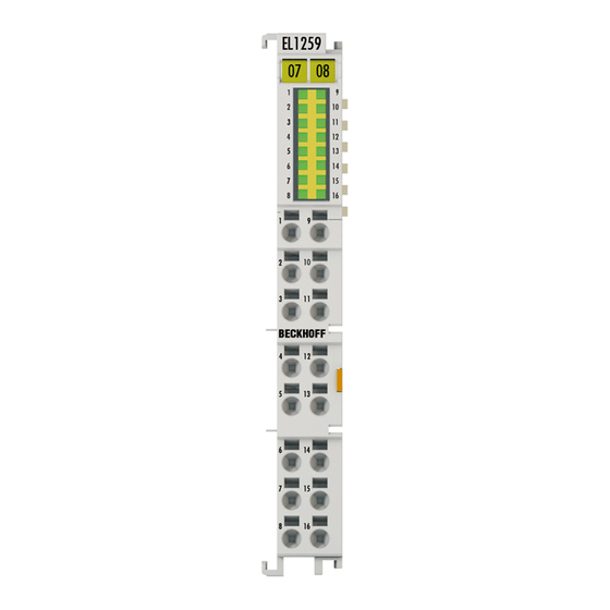
Fig. 10 EL1259
Fig. 40 EL1259
Fig. 11 EL2258
Fig. 41 EL2258
6 Commissioning
Twincat Quick Start
Twincat 2
Twincat 3
Twincat Development Environment
Installation of the Twincat Real-Time Driver
Notes Regarding ESI Device Description
Distinction between Online and Offline
Twincat ESI Updater
OFFLINE Configuration Creation
ONLINE Configuration Creation
Ethercat Subscriber Configuration
Fig. 132 „Startup" Tab
Fig. 133 "Coe - Online" Tab
Fig. 134 Dialog "Advanced Settings
Fig. 135 „Online" Tab
Fig. 136 "DC" Tab (Distributed Clocks)
General Notes - Ethercat Slave Application
Fig. 137 Selection of the Diagnostic Information of an Ethercat Slave
Fig. 138 Basic Ethercat Slave Diagnosis in the PLC
Fig. 139 EL3102, Coe Directory
Fig. 140 Example of Commissioning Aid for a EL3204
Fig. 141 Default Behaviour of the System Manager
Fig. 142 Default Target State in the Slave
Fig. 143 PLC Function Blocks
Fig. 144 Illegally Exceeding the E-Bus Current
Fig. 145 Warning Message for Exceeding E-Bus Current
Basic Function Principles
Definitions
Fig. 146 Microcycle 0Xf900:09 & Macrocycle 0Xf900:08 in the Coe
Fig. 147 Microcycle 0Xf900:09 & Macrocycle 0Xf900:08 in the Coe
Compatibility Mode in Relation to EL1252/EL2252
Fig. 148 Option for Setting of Compatibility Modes in Relation to EL1252/EL2252
Fig. 149 Setting Multi-Timestamping Via "Predefined PDO
Fig. 150 Free Selection of the PDO
Commissioning Inputs
Basic Principles
Fig. 151 Event Logger Message from the System Manager in the Event of Invalid PDO Combination
Fig. 152 Inputs and Outputs in the Project Tree
Fig. 153 Operating Mode Selection in Coe from 0X80N0
Commissioning of a MTI Channel
Fig. 154 Setting in Coe X80N0:12 Asynchronous Operation
Fig. 155 Process Data Selection (Predefined PDO) for Synchronous Transfer
Fig. 156 Process Data Selection (Predefined PDO) for Asynchronous Transfer
Fig. 157 Different MTSF
Fig. 158 Setting in Coe X80N0:01 & X80N0:14 for Digital Filter
Commissioning in Compatibility Mode
Fig. 159 Timestamp Via Online Display
Commissioning Outputs
Fig. 160 Predefined Pdos for Compatibility Mode
Basic Principles
Fig. 161 Inputs and Outputs in the Project Tree
Fig. 162 Operating Mode Selection in Coe from 0X80N1
Commissioning an MTO Channel
Fig. 163 Enabletimececk Mode 1-3
Fig. 164 Manual Control
Fig. 165 Output in +24 V Continuous Mode
Fig. 166 Process Data Selection (Predefined PDO) for Synchronous Transfer
Commissioning in Compatibility Mode EL2252
Fig. 167 Predefined Pdos for Compatibility Mode
Distributed Clocks Settings
Fig. 168 Activation of the Master Distributed Clock Display
Fig. 169 Extended Process Image of the Ethercat Master
Fig. 170 Setting Systime
Coe Object Description and Parameterization
El1258
El1259
El2258
Example Programs
Fig. 171 Opening the *. Tnzip Archive
Fig. 172 Search of the Existing HW Configuration for the Ethercat Configuration of the Example
Example Program for EL2258: Multi-Timestamp
Fig. 173 Recording of Four Channels by the Multi-Timestamp Program Example
Fig. 174 Recommended Structure for the EL1258 Sample Program
Fig. 175 Coe Object 0X8000 (MTI Settings Ch.1): Settings for the Sample Program
Fig. 176 Sample Program EL1258 / Visualization_1: Simple Time Measurement Based on Two State Changes
Appendix
Device Description ESI File/Xml
Firmware Explanation
Updating Controller Firmware *.Efw
FPGA Firmware *.Rbf
Simultaneous Updating of Several Ethercat Devices
Restoring the Delivery State
Support and Service
List of Illustrations
Advertisement
Quick Links
1
El1258, El1259, El2258
Download this manual
Documentation
EL125x, EL2258
8 channel digital input/output terminal with time stamp
Version:
Date:
2.5
2017-12-07
Table of
Contents
Previous
Page
Next
Page
1
2
3
4
5
Advertisement
Chapters
Table of Contents
4
List of Illustrations
307
Table of Contents
Need help?
Do you have a question about the EL1258 and is the answer not in the manual?
Ask a question
Questions and answers
Related Manuals for Beckhoff EL1258
Touch terminals Beckhoff TwinSAFE EL1904 Operating Instructions Manual
Terminal with 4 digital fail-safe inputs (67 pages)
Touch terminals Beckhoff EL1904 Operating Instructions Manual
Twinsafe terminal with 4 digital fail-safe inputs (46 pages)
Touch terminals Beckhoff EL1904 Operating Instructions Manual
Twinsafe terminal with 4 digital fail-safe inputs (57 pages)
Touch terminals Beckhoff EL1259 Documentation
8 channel digital input/output terminal with time stamp (311 pages)
Touch terminals beckhoff EL1512 Documentation
Up/down counter 24 vdc (167 pages)
Touch terminals beckhoff EL1502 Documentation
Up/down counter 24 vdc (167 pages)
Touch terminals Beckhoff EL1918 Operating Instructions Manual
Twinsafe terminal with 8 digital fail-safe inputs (55 pages)
Touch terminals Beckhoff EL1918 Operation Manual
Twinsafe terminal with 8 digital fail-safe inputs (63 pages)
Touch terminals Beckhoff TwinSAFE EL1918 Operating Instructions Manual
Terminal with 8 digital fail-safe inputs (69 pages)
Touch terminals Beckhoff EL1054 Documentation
Digital input terminals for namur sensors (97 pages)
Touch terminals Beckhoff EL1052 Documentation
Digital input terminals for namur sensors (97 pages)
Touch terminals Beckhoff EL10 Series Documentation
Digital input terminals (106 pages)
Touch terminals Beckhoff EL6910 Operation Manual
Twinsafe logic terminal (105 pages)
Touch terminals Beckhoff EL6751 Documentation
Master/slave terminal for canopen (210 pages)
Touch terminals Beckhoff ELX9560 Operating Manual
Two- and eight-channel analog input terminals, 0/4 ... 20 ma, single ended, 16 bit, ex i (36 pages)
Touch terminals Beckhoff ELX9012 Operating Manual
Two- and eight-channel analog input terminals, 0/4 ... 20 ma, single ended, 16 bit, ex i (36 pages)
This manual is also suitable for:
El1259
El2258
Table of Contents
Print
Rename the bookmark
Delete bookmark?
Delete from my manuals?
Login
Sign In
OR
Sign in with Facebook
Sign in with Google
Upload manual
Upload from disk
Upload from URL


Need help?
Do you have a question about the EL1258 and is the answer not in the manual?
Questions and answers