
Related Manuals for CAME VER-PLUS Series


Summary of Contents for CAME VER-PLUS Series
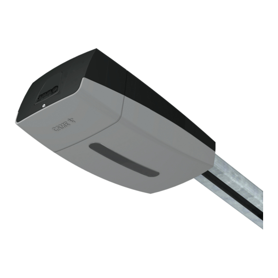
- Page 1 Garage-door operator FA01358-EN VER-PLUS series VER10DMS-VER13DMS EN English INSTALLATION MANUAL...
- Page 3 This product must only be used for its specifi cally intended purpose. Any other use is dangerous. Came S.P.A. is not liable for any damage caused by improper, wrongful and unreasonable use. • This manual's product is defi ned by machinery directive 2006/42/ CE as "partly-completed machinery".
- Page 4 the products that make up the fi nal machinery • set up a suitable dual pole cut off device along the power supply that is compliant with the installation rules. It should completely cut off the power supply according to category III surcharge conditions • The gear motor must be only powered by very low safety voltage, which corresponds to what is stated in the markings on the gear motor •...
- Page 5 This symbol shows which parts to read carefully. ⚠ This symbol shows which parts describe safety issues ☞ This symbol shows which parts to tell users about. The measurements, unless otherwise stated, are in millimeters. DESCRIPTION Automated operator featuring a control panel with encoder for sectional and overhead garage doors. Intended use The VER10DMS / VER13DMS operators are developed to drive overhead and sectional garage-doors in private homes and apartment buildings.
- Page 6 Dimensions 3020 ÷ 4020 Description of parts Operator Cover Gear motor Transformer Control board Operator confi guration buttons ❶ Standard drive arm for the VER10DMS* ⓬ Standard drive arm for the VER13DMS* Door fastening brace Guide fastening brace ⓮ ❻ 10.
- Page 7 Guide Guide Chain or belt Sliding guide with release tab Mechanical stop ❺ Support rods ❷ ❸ ❹ ❶ Chain drive 001V0679 Chain guide L = 3.02 m. Counter-balanced overhead doors up to 2.4 m in height - Counter-balanced overhead doors up to 2.25 m in height - Sectional* doors up to 2.20 m in height.
- Page 8 Accessories 001V005 Extension for the following types of chain guides: V0679, V0682, V0683, V0684. 001V201 Transmission arm for partially retracting overhead garage-doors. Transmission arm for sectional doors having a top-rail to spring-pole assembly distance 001V122 comprised between 300 and 600 mm. 001V121 Pull-cord auto-resetting release device to fi...
- Page 9 Standard installation Operator Guide Release device Transmission arm Key-switch selector Photocells Control device Sensitive safety-edge Flashing light and antenna ❸ ❶ ❷ ❾ ❹ ❺ ❼ ❻ ❽ ❻...
- Page 10 GENERAL INSTALLATION INDICATIONS ⚠ Only skilled, qualifi ed staff must install this product. Cable type and minimum thicknesses cable length Connection < 20 m 20 < 30 m Control panel power supply 230 V AC 3G x 1.5 mm 3G x 2.5 mm Flashing light 2 x 0.5 mm Command and control devices...
- Page 11 INSTALLATION Only skilled, qualifi ed staff must install this product. ⚠ The following illustrations are mere examples in that the space for fastening the operator and accessories ⚠ varies depending on the installation area. It is up to the fi tter, therefore, to choose the most suitable solution. Assembling the guide ❶...
- Page 12 For protracting overhead doors, keep the guide 20 mm from the opening high-point. V201 ☞ For protracting, partially retracting overhead doors, use the V201 transmission arm (optional accessory). Fastening the cover Fasten the hinge to the cover by using the supplied screws ❶. Fit the cover onto the operator ❷. ❶...
- Page 13 Fastening the guide-shaft Fasten the guide-shaft to the center of the door opening. Use suitable bolts ❶. Raise the guide-shaft and position it horizontally to measure the distance from the ceiling, and then fasten it. ❷. ❶ ❷ Fasten the braces to the guide and directly to the ceiling or use the supplied extensions and adapt them to the required height ❸.
- Page 14 Turn the release tab counter-clockwise ❺. Move the traction assembly towards the door ❻ and fasten the transmission arm using the supplied bolt ❼. ❺ ❻ ❼ UNI 5739 M6 x 20 Fitting the operator to the guide Fasten the operator to the guide-shaft by using the supplied screws ❶. ...
- Page 15 Perforate the cable gland ❸ run the cables through ❹ and fi t the cable gland into its brace ❺. The number of cables depends on the type of system and accessories fi tted. ❹ ❺ ❸ ELECTRICAL CONNECTIONS AND PROGRAMMING ⚠...
- Page 16 Description of parts Courtesy light 16. RSE card connector Encoder terminal board • It excludes local connection with Came Gear motor terminal board Key. Control board terminal board 17. Terminal board for control and safety devices Accessories fuse 18. Terminal board for warning devices Motor fuse 19.
- Page 17 Input voltage Ref. Description Ⓛ HD Analog Ground 230 V AC - 50/60 Hz Ⓝ Neutral Accessories power supply output 24 V AC/DC, max 20 W 24 V AC/DC control board power-supply input Factory wiring Green 24 V DC gearmotor Green Encoder Brown...
- Page 18 Command and control devices ⚠ For the system to work properly, before fi tting any plug-in card, such as the AF or R800 one, you MUST CUT OFF THE MAINS POWER SUPPLY and, if present, disconnect any batteries. Connector for the R700 card (for using the transponder or the card reader) or for the R800 card (for using the keypad selector).
- Page 19 Safety devices Photocells Confi gure contact CX or CY (NC), safety input for photocells. See CX input functions (Function F 2) or CY (Function F 3) in: - C1 reopening during closing. When the door is closing, opening the contact causes the door to invert its move- ment until it is completely open.
- Page 20 Sensitive Safety Edges Confi gure contact CX or CY (NC), safety input for safety devices such as sensitive safety-edges. See CX input functions (Function F 2) or CY (Function F 3) in: - C7 reopening during closing (NC input). When the door is closing, opening the contact causes the door to invert its movement until it is completely open.
- Page 21 Linking up with Came Remote Protocol(CRP) ⚠ Before plugging in the card YOU MUST CUT OFF THE MAINS POWER SUPPLY and, remove any batteries. Using the RSE card excludes the local connection with CAME KEY. Fit the RSE card. 1 2 3 4...
- Page 22 Transmitter and data storage Memory Roll ⚠ Before plugging in the card YOU MUST CUT OFF THE MAINS POWER SUPPLY and, remove any batteries. To enter, change and delete user or to control the operator via the radio command, fi t the AF card.
- Page 23 Functions menu IMPORTANT! Start programming by fi rst performing the TOTAL STOP (F1) and CALIBRATING TRAVEL (A3) functions Only program functions when the operator is stopped. You can save up to 250 users. NC input – Door stops and excludes any automatic closing; to resume movement, use the control device.
- Page 24 The LED , connected to 10-5, signals the state of the door. Output for 0 = Steady lit with door open and moving (default) / 1= Blinks intermittently - state-of-door every half second, during opening, and - every second, during closing. It stays signal lit when the door is open and switches off when the door is closed.
- Page 25 OFF = Deactivated / 1 = 1% of the door travel (minimum) / … / 5 = 5% of the closing door travel (default) / … / 50 = 50% of the door travel (maximum) Managing For enabling the CRP (Came Remote Protocol). the serial 0 = Deactivated / 3 = CRP (default) connection Saving users and settings saved in the Memory Roll.
- Page 26 To set the peripheral number from 1 to 255 for each control board when a Peripheral system is fi tted with several operators and features the CRP (Came Remote number Protocol) connection system. 1 ----> 255 For setting the communication speed used in the CRP (Came Remote Protocol) connection system.
- Page 27 Select the type of transmitter radio coding that you wish to save on the control board. ⚠ When you select a radio coding, all saved transmitter are automatically Decoding the deleted. radio-frequency TWIN's coding lets you save multiple users with the same key (Key block). code 1 = all of the series (default)/2 = only Rolling Code series /3 = only TWIN series...
- Page 28 List of registered users Download the LIST OF REGISTERED USERS form from the portal docs.came.com. Enter L20180423. Entering a user with an associated command N.B.: when entering/deleting users, the numbers displayed in fl ashing mode, are numbers that are avai- lable for other users (max.
- Page 29 Deleting a single user Select U2. Press ENTER to confi rm ❶. Select the user number to delete. Press ENTER to confi rm. ❷. The Clr wording will appear to confi rm the deletion ❸. ❶ ❷ ❸ Motor test Select A2.
- Page 30 Gate-swing calibration N.B.: before calibrating the travel, check that the maneuvering area is free of any obstructions. Important! During the calibration, all safety devices will be disabled except for the PARTIAL STOP one. Select A3. Press ENTER to confi rm ❶. Select 1 and press ENTER to confi...
- Page 31 Encoder operation Obstruction detection when OPENING. The door recloses. Obstruction detection when CLOSING. The door inverts its travel direction and reopens. After two consecutive inversions, when closing, the door stays open and the automatic closing is excluded. After three consecutive detections, when opening and/or closing, the door stops. To reclose the door, press a control button or use the transmitter.
- Page 32 WHAT TO DO IF ... ISSUES POSSIBLE CAUSES POSSIBLE FIXES The operator opens but • Power supply is missing • Check main power supply will not close • The gear motor is stuck • Lock the gear motor • The transmitter emits a weak signal •...
- Page 33 DISMANTLING AND DISPOSAL ☞ CAME S.p.A. applies a certifi ed Environmental Management System at its premises, which is compliant with the UNI EN ISO 14001 standard to ensure the environment is safeguarded. Please continue safeguarding the environment. At CAME we consider it one of the fundamentals of our operating and market strategies.
- Page 36 CAME S.p.A. Via Martiri Della Libertà, 15 31030 Dosson di Casier - Treviso - Italy tel. (+39) 0422 4940 - fax. (+39) 0422 4941...
Need help?
Do you have a question about the VER-PLUS Series and is the answer not in the manual?
Questions and answers