Advertisement
SERIE
CANCELLI AUTOMATICI
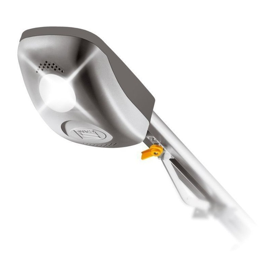
AUTOMATIC TRACTION SYSTEM FOR OVERHEAD AND SECTIONAL DOORS
9
10
T RG58
2x1,5
11
2x1
6
1 - VER unit
2 - Incorporated control panel
3 - Radio receiver
4 - Internal pushbutton array
5 - Safety photocells
6 - Rubber safety section
VER
V900E
Standar installation
7
TX
RX
6
1
8
4
6x1,5
5
7 - Transmission arm
8 - Release mechanism
9 - Antenna
10 - Flashing light
11 - Key-operated selector switch
Documentazione
Tecnica
T44
rev. 1.0
02 / 2004
©
CAME
CANCELLI AUTOMATICI
119ET44-GB
2
3
Advertisement
Table of Contents

Related Manuals for CAME V900E


Summary of Contents for CAME V900E
- Page 1 SERIE Documentazione Tecnica rev. 1.0 V900E 02 / 2004 © CAME CANCELLI AUTOMATICI 119ET44-GB CANCELLI AUTOMATICI AUTOMATIC TRACTION SYSTEM FOR OVERHEAD AND SECTIONAL DOORS Standar installation T RG58 2x1,5 6x1,5 1 - VER unit 7 - Transmission arm 2 - Incorporated control panel...
-
Page 2: General Specifications
V122 - Improved transmissionarm for sectional gates, see pg. Versions V900E - Encoder controlled 24V (D.C.) gearmotor with built-in control panel; 230V AC power with 50÷60Hz frequency; 130W max. motor power and up to 500N in traction power. -
Page 3: Unit Assembly
EXEMPLES OF APPLICATIONS COUNTERWEIGHTED OVERHEAD DOOR, outward vertical stroke and partially inward entry type SPRING-BALANCED OVERHEAD DOOR, spring balanced, outward vertical stroke and totally inward entry type SECTIONAL DOOR single sliding rail double sliding rail UNIT ASSEMBLY PREARRANGEMENT OF TRANSMISSION RAIL - Fasten the bracket to the transmission guide’s front terminal with the screws provided;... - Page 4 TRANSMISSION RAIL FASTENING - Fasten the transmission rail in the following manner: a) for sectional doors C-type (see ref. p.4), fasten the bracket directly over the spring-release coiling shaft using adequate dowels and screws; if the distance between the coiling shaft and the gate’s upper ledge is between 30 and 60 cm, apply the V122 arm (read the technical documentation provided with the accessory);...
-
Page 5: Gearmotor Installation
SLIDING LEVER FASTENING - Centrally fix the transmission arm to the door’s upper crosspiece with the rivets provided (or possible screws); - Move the sliding runner and hook it to the transmission arm after removing the preset screw. N.B.: if the adapter arm (V201) is used, hook the carriage to the sliding runner. GEARMOTOR INSTALLATION - Remove the automation container cover by unscrewing the ø3.9x13 screw;... - Page 6 VERDE - GREEN - VERT - GRÜN - VERDE ROSSO - RED - ROUGE - ROT - ROJO FUS. ACC. 3,15A BIANCO - WHITE - BLANC - WEIß - BLANCO MARRONE - BROWN - MARRON - BRAUN - CASTAÑO VERDE - GREEN - VERT - GRÜN - VERDE VERDE/GIALLO - GREEN/YELLOW - VERT/JAUNE GRÜN/GELB - VERDE/AMARILLO...
-
Page 7: Electrical Connections
ELECTRICAL CONNECTIONS N.B. All the contacts and push-buttons normally closed (N.C.) that are not used must be short-circuited. 10 11 E 1 2 7 C1 + E - 230V (a.c.) power supply 24 (d.c.) motor Powering accessories (max 40W) + 10 - 24V (A.C.) with power supply at 230V (A.C.) - 11 - 24V (D.C.) with power supply at 24V (A.C.) - Page 8 ENCODER PROGRAMMING MPORTANT READ INSTRUCTIONS CAREFULLY BEFORE PROCEEDING WITH PROGRAMMING closure limit switch Set dip-switch 1 to ON: the red LED comes on, at slow intermittence. Keep the “AP-CH” button pressed and allow the overhead door to reach the limit switch when it closes. Press and release the “ENC/RADIO”...
- Page 9 opening limit switch Keep the “APRE” button pressed and allow the door to open fully. Press and release the “ENC/RADIO” button: the signalling LED remains on to indicate that the closing end-stop has been saved. With the door open, position the end-stop (in the transmission guide) on the sliding runner and secure it with the screws. Set dip-switch 1 to OFF.
-
Page 10: Radio Control Installation
RADIO CONTROL INSTALLATION PROCEDURE A - Insert an AF card**. B - Encode transmitter/s. C - Store code in the motherboard. - AF board insertion T.C.A. SENS. FUS. MOTORE 7.5A AP / CH APRE ENC/RADIO AF board + E - 26V17V 0V FUS. - Page 11 T432M - T312M set the code to dip-switch C and channel to D (P1=CH1 and P2=CH2, default setting) - Code storage - Keep the “ENC/RADIO” key pressed on the base card (the signal LED will flash), and with a key on the transmitter the code is sent, the LED will remain lit to signal the successful saving of the code.
-
Page 12: Manufacturer's Declaration
COMMERCIAL AND OTHER CLOSING MECHANISMS (+39) 0422 4940 - fax (+39) 0422 4941 EN 12445 NDUSTRIAL COMMERCIAL AND OTHER CLOSING MECHANISMS internet: www.came.it - e-mail: info@came.it EN 60335 - 1 AFETY IN APPARATUSES FOR HOME USE EN 60204 - 1 ACHINERY SAFETY Hereby declare, under their own respons ibility, that the product/s called ...
Need help?
Do you have a question about the V900E and is the answer not in the manual?
Questions and answers