CAME VER Series Installation Manual
Garage door operator
Hide thumbs
Also See for VER Series:
- Manual (29 pages) ,
- Instructions manual (28 pages) ,
- Quick manual (2 pages)

Related Manuals for CAME VER Series


Summary of Contents for CAME VER Series
- Page 1 Garage door operator FA01176-EN Series VER VER06DES-VER08DES EN English INSTALLATION MANUAL...
- Page 3 This product must only be used for its specifi cally intended purpose. Any other use is dangerous. CAME S.p.a. is not liable for any damage caused by improper, wrongful and unreasonable use • This manual's product is defi ned by the Machinery Directive 2006/42/EC as partly-completed machinery.”.
- Page 4 what is stated in the markings on the gearmotor itself • Keep the section of this manual inside the technical folder along with the manuals of all the other devices used for your automation system. Remember to hand over to the end users all the operating manuals of the products that make up the fi...
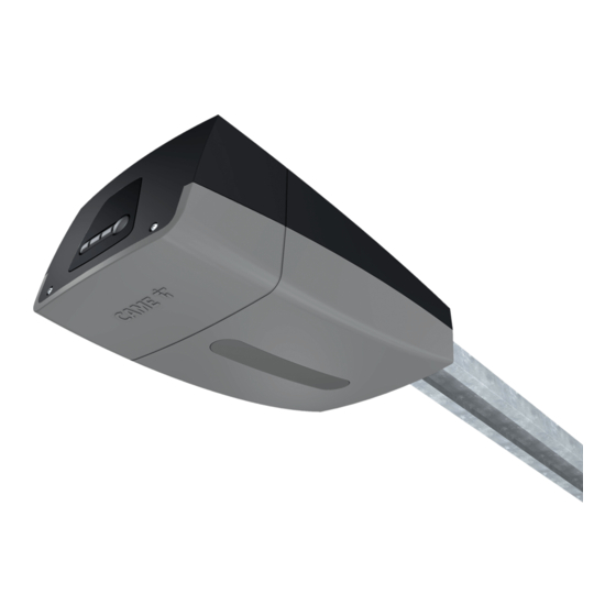
- Page 5 This symbol shows which parts to read carefully. ⚠ This symbol shows which parts describe safety issues. ☞ This symbol shows which parts to tell users about. The measurements, unless otherwise stated, are in millimeters. DESCRIPTION Operator featuring a control panel with encoder for sectional and overhead garage doors. Intended use The VER06DES / VER08DES operators are designed to power overhead garage and sectional doors for homes and apartment blocks.
- Page 6 Dimensions 3020÷4020 Description of parts ❶ Operator ❶ Cover ❷ Gearmotor ❸ Transformer ❹ Electronic board ❸ ❺ Operator confi guration buttons ❹ ❷ ❺...
- Page 7 Packing list ⓫ one (ø8x25) drive-shaft adapter ⓬ one 3x20 linchpin ❶ one Operator ⓭ one Pin ❷ one Installation Manual ⓮ four M8x20 hexagonal screws with washers and ❸ two anchoring perforated-plates. nuts ❹ one Curved lever ⓯ one Slide guide (only in kit with 3 pieces of ❺...
- Page 8 Pre-assembled guide package ❹ ❶ Guide ❺ ❷ Chain or belt ❸ Skid ❸ ❹ Transmission arm ❶ ❺ Release cord ❷ Slide guides 001V06001 Chain guide L = 3.02 m. Counter-balanced overhead doors up to 2.4 m in height - Counter-balanced overhead doors up to 2.25 m in height.
-
Page 9: Sectional Door
Application examples Types and limits to use SECTIONAL DOOR Sectional door with double Sectional door with single slide-guide slide-guides COUNTER-BALANCED OVERHEAD DOORS, SPRING-BALANCED OVERHEAD DOOR, PARTIALLY RETRACTING AND PROTRUDING FULLY RETRACTING AND PROTRUDING... -
Page 10: Standard Installation
Standard installation ❶ Operator ❷ Guide ❸ Release device ❹ Transmission arm ❺ Key-switch selector ❻ Photocells ❼ Control device ❽ Sensitive safety-edge ❾ Flashing light and antenna ❷ ❸ ❶ ❾ ❹ ❺ ❼ ❻ ❽ ❻... - Page 11 GENERAL INSTALLATION INDICATIONS ⚠ The installation must be done by qualifi ed expert technicians and in full compliance with applicable laws and regulations. Cable type and minimum thicknesses cable length Connection < 20 m 20 < 30 m Control panel power supply 230 V AC 3G x 1.5 mm 3G x 2.5 mm Flashing light...
- Page 12 INSTALLING ⚠ The installation must be done by qualifi ed expert technicians and in full compliance with applicable laws and regulations. The following illustrations are mere examples in that the space for fastening the operator and accessories ⚠ varies depending on the installation area. It is up to the fi tter, therefore, to choose the most suitable solution. Assembling the guide ❷...
- Page 13 For protracting overhead doors, keep the guide 20 mm from the opening high-point. ☞ For protracting, partially retracting overhead doors, use the V201 transmission arm (optional accessory). Fastening the traction guide Fasten the traction guide to the center of the doorway, using suitable screws. ...
- Page 14 Bend the perforated fl at tabs so they fi t snugly and so as to compensate for the distance between the guide and ceiling. Fasten the fl at tabs to the support braces and to the U-shaped brace using the supplied screws and washers. Drill the ceiling so the holes match those on the fl...
- Page 15 Fitting the operator to the guide Fit the adapter to the drive shaft. The operator can be fi tted onto the guide: either in standard position or at a right angle . Self-drilling 6 x 15 screw U-shaped brace Guide Micro Adapter...
- Page 16 Moving the micro switch Disconnect the cables of the micro switch and remove the latter. Remove the operator's cover. Pull out the electrical cable and fi t it through the hole. Use a screwdriver to open up the predrilled hole for the electrical cables of the micro switch and fi r the cables to the micro switch.
- Page 17 Perforate the cable gland ❶ pass the cables through ❷ and fi t it into its corresponding housing ❸. The number of cables depends on the type of system and accessories fi tted. ❷ ❸ ❶...
- Page 18 Description of parts ❶ Encoder connector ❾ Safety-device terminals ❷ Gearmotor connector ❿ Line power-supply connector ❸ Card power supply connector ⓫ Courtesy light cover connector ❹ Electronic board ⓬ Calibration microswitch terminal ❺ AF card connector ⓭ Programming board ❻ Antenna terminals ⓮...
-
Page 19: Signalling Devices
Signalling devices Output for connecting either fl ashing or cycle light (Contact rated for: 24 V AC - 10 W). See function F18. Output for connecting the accessories. Maximum absorption of all the devices: max. 20 W. - Page 20 Command and control devices ⚠ Before fi tting the AF card, you must cut off the mains power supply. Antenna with RG58 cable for remote control. Connector for AF card for remote control. OPEN-CLOSE-INVERT (step-by-step) function STOP button (NC contact). Enables the door to stop from control device (NO contact).
-
Page 21: Safety Devices
Safety devices Photocells Confi gure contact CX or CY (NC), safety input for photocells. See functions for input CX (Function F 2) or CY (Function F 3) in: - C1 reopening during closing. When the door is closing, opening the contact causes the door to invert its move- ment until it is completely open;... -
Page 22: Browsing The Menu
Sensitive Safety Edges Confi gure contact CX, CY (NC), safety input for sensitive safety-edges. See functions for input CX (Function F 2) or CY (Function F 3) in: - C7 reopening while closing (NC input). When the door is closing, opening the contact causes the door to invert its movement immediately until it is completely open;... -
Page 23: Functions Menu
Functions menu IMPORTANT! Start programming by fi rst performing the TOTAL STOP (F 1) and TRAVEL CALIBRATION (A3) functions Only program functions when the operator is stopped. You can save up to 250 users. NC input – Door stop that excludes any automatic closing; to resume movement, use the control device. - Page 24 The automatic-closing wait starts when the partial opening point is reached (from Automatic partial opening command) and can be set to between 1 and 180 seconds. The closing time automatic closing does not activate, after a total stop or if the power supply is after partial missing.
- Page 25 List of registered users...
- Page 27 Transmitter and Saving users ⚠ Before fi tting the snap-in cards, you MUST CUT OFF THE MAINS POWER SUPPLY. To enter, change and delete user or to control the operator via the radio command, fi t the AF card. Entering a user with an associated command N.B.: when entering and deleting users, the numbers that appear fl...
-
Page 28: Deleting A Single User
Deleting a single user ❶ Select U2. Press ENTER to confi rm ❷ Select the user number to delete. Press ENTER to confi rm ❸ The Clr wording will appear to confi rm the deletion N.B.: It is possible to directly delete an already memorized transmitter. At point ❷ press the remote control button to identify the position it occupies. -
Page 29: Encoder Operation
Encoder operation Obstruction detection when OPENING. The door closes again. Obstruction detection when CLOSING. The door inverts its travel direction and reopens. After three consecutive inversions, when closing, the door stays open and automatic closing is excluded. After three consecutive opening or closing detections, the door stops. To close the door again, press a control button or use the transmitter. -
Page 30: Final Operations
Do the fi nal operation only once the connections are complete and the system is started up. DISMANTLING AND DISPOSAL ☞ CAME S.p.A. employs an Environmental Management System at its premises. This system is certifi ed and compliant with the UNI EN ISO 14001 regulation standard to ensure that the environment is respected and safeguarded. - Page 32 The contents of this manual may change, at any time, and without notice. CAME S.p.A. Via Martiri Della Libertà, 15 31030 Dosson di Casier - Treviso - Italy tel. (+39) 0422 4940 - fax. (+39) 0422 4941...
Need help?
Do you have a question about the VER Series and is the answer not in the manual?
Questions and answers