Table of Contents
Advertisement
Advertisement
Table of Contents

Subscribe to Our Youtube Channel
Related Manuals for CAME V700E


Summary of Contents for CAME V700E
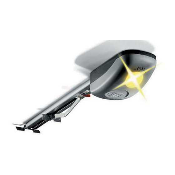
- Page 1 AUTOMATION FOR SECTIONAL AND OVERHEAD DOORS INSTALLATION MANUAL V700E English...
-
Page 2: Read Carefully
Warning Sings (e.g. gate plate). (i.e. that for which it was expressly built for). Any other use is Special instructions and to be considered dangerous. Came Cancelli Automatici S.p.A. advice for users is not liable for any damage resulting from improper, wrongful •... -
Page 3: General Conditions Of Sale
3. ORDERS The sale agreement is executed once the written order is confirmed by Came Cancelli Automatici Spa or when the order is fulfilled by the company. Orders that are addressed, and signed by clients, to Came Cancelli Automatici SpA are deemed to be firm and irrevocable for 30 days starting from the date they are received by the company. -
Page 4: Reference Standards
4 Description 4.1 Automation V700E was designed and manufactured by CAME CANCELLI AUTOMATICI S.p.A. and is compliant with the safety regulations in force. Guaranteed 24 months if not tampered with. The automation is mainly made up of an engine block, a transmission rail - with either a belt or chain transmission system - and a transmission arm. -
Page 5: Technical Specifications
2) 001V0670 - Emergency battery start-up card, houses 2 (12V-1,2Ah not included) batteries ; Important! Check that the safety equipment and accessories are CAME originals; this is a guarantee that also makes the system easy to set up and upkeep. -
Page 6: Installation
4.4 Dimensions 5 Installation The installation must be carried out by export, qualified personnel in total compliance with the norms in effect. 5.1 Preliminary checks Before proceeding with the installation, it is necessary to: • Make sure the area selected for the mounting of the base and for the unit itself is hazard free; •... - Page 7 5.3 Cable list and minimum thickness Connections Type of cable Length of cable 1 < 10 m L. of cable 10 < 20 m L. of cable 20 < 30 m 230V power supply 3G x 1,5 mm 3G x 2,5 mm 3G x 4 mm Flashing lamp 2 x 0,5 mm...
- Page 8 5.5 Preparing the transmission guide The following applications are only examples, as the space required for unit installation and the accessories vary depending on dimensions and therefore it is up to the installer to select the best solution. 1) Fasten the bracket to the tension device on the transmission guide using the supplied bolts and washers. M6 x 20 2) Position the transmission guide in the following manner: - for sectional doors directly above spring-release coiling shaft (between 20 and 30 mm of the shaft’s axis).
- Page 9 5.6 Fastening the transmission guide 1) Fasten the transmission guide to the centre of the doorway using the proper screws. Raise the guide until it is horizontal with the ceiling so as to choose the proper type of fastener. 2) If the angle brackets are not suffi cient, cut the tension brackets down to the right length and fasten them to the ceiling. N.B.: to strengthen the bar additional angle or tension brackets may be installed (item code 119RIE024 and 119RIE028) M6 x 14 3) Fasten the transmission guide to the ceiling using the proper bolts.
- Page 10 5.7 Fastening the guide arm to the transmission guide 1) Fasten the guide arm to the top of the door frame, perpendicularly to the transmission guide. Use the supplied rivets and other suitable bolts and screws. 2) Release the traction slide by turning the small level clockwise. Move the slide towards the door and hook it onto the guide arm with the supplied bolt.
- Page 11 5.8 Fastening the gearmotor to the transmission guide 1) Remove the cover of the motor unit. UNI 6954 ø 3.9 x 13 2) Fasten the motor unit to guide’s support racket using the three screws supplied with the kit. N.B.: if needed, the unit may be fasten in the other three perpendicular positions, as per the drawings. UNI 6955 ø...
-
Page 12: Electronic Control Panel
6 Electronic control panel 6.1 General description The control panel is powered by 230V on the L-N terminals, with a 50/60 Hz frequency. The command devices and accessories run on 24V. Moreover, the total accessories cannot run on more than 40W. The panel controls a service light to light up the service area;... -
Page 13: Main Components
6.2 Main components 1) Line fuse 1.6A 2) Emergency batteries’ slot 3) Gearmotor 4) Transformer 5) Transformer connection terminal board 6) Motor fuse 8A 7) Gearmotor connection terminal board 8) Encoder connection terminal board 9) Signal Led for radio-code and encoder programming 10) Radio-code save button 11) SLOW. - Page 14 Gearmotor, encoder and transformer (only for possibile maintenance) Gearmotor Transformer 24V d.c. with encoder Command and safety devices If a device is connected up, remove the small bridge. Stop button (N.C. contact) - Stops movement, excludes the automatic closing functions. To restart the automated kit, press a command button or a remote control button.
-
Page 15: Function Selection
Warning devices Movement Flasher (contact capacity: 24V – 25W max.) Flashes during the opening and closing phases. 6.4 Function selection 1 ON - Activates the procedure for adjusting the opening and closing endpoints and the procedure for programming the decelerated opening. - Page 16 7 Programming 7.1 Programming the end-stop in the closing and opening phase IMPORTANT: before performing any programming, read the instructions carefully. Carry out the following instructions in the proper order otherwise the programming will fail. 1 - Preliminary operations - Release the automation and position the door in the fully opened position. - When the door is fully opened, fasten the mechanical stop to the traction slide.
- Page 17 ...then press the ENC/RADIO button until the signalling led stays on for some seconds and then resumes blinking (the programming operation is satisfactorily complete). OPEN ENC/RADIO OPEN ENC/RADIO CL.SENS. OP.SENS. OP / CL CL.SENS. OP.SENS. OP / CL SLOW.SENS A.C.T. SLOW.SENS A.C.T.
- Page 18 7.2 Programming for partial opening With the door is completely closed, set DIP switch 2 to ON (the signalling led fl ashes). Press and keep the OPEN button pressed until the door reaches the desired point of opening..then press the ENC/RADIO button (if the signalling LED stays on the programming procedure is successfully complete). Set DIP switch 2 back to OFF OP.SENS.
- Page 19 Press the OP/CL button until the gate reaches the fi nal point of deceleration you require; then press the ENC/RADIO button until the signalling LED staus on ( the programming procedure is completed succesfully). Set DIP switch 1 back to OFF. 7.4 Programming for closing deceleration (600 mm from the closing stop minimum, or 50% of the opening/closing arc) With the door completely closed, press and keep pressed the ENC/RADIO button (the signalling programming LED fl...
-
Page 20: Activating The Remote Control
8 Activating the remote control 1 - Antenna Connect the antenna with the RG58 cable to the apposite terminals on the board. 2 - Radio frequency Connect the radiofrequency card to the electrical board AFTER SHUTTING OFF THE POWER (or disconnecting the batteries). N.B.: The circuit board recognizes the readiofrequency card only when it is running in electrical power. - Page 21 4 - Memorising and deleting radio users Activating the (2-7) sequential command Keep the ENC/RADIO pressed on the circuit board. The led indicator will fl ash. press the transmitter button (T1) to be memorised. The led indicator will stay on to confi rm memorisation. ENC/RADIO Lit LED AF Card...
-
Page 22: Important Safety Instructions
9 Safety instructions Important safety instructions This product must only be employed for its originally intended use. Any other use is wrong and potentially dangerous. The manufacturer cannot be held liable for any damages resulting from wrongful, erroneous or negligent uses. Avoid working close to the hinges or other moving mechanical parts. -
Page 23: Problem Solving
- To clean the photocells use a water dampened cloth. Do not use solvents or other chemical products which may ruin the devices. - In the event of any strange vibrations or squeaking, lubricate the joints with grease, as shown in the diagram. - Make sure there are no plants within the photocell’s beam, and that the heavy door motion is free of any obstacles. -
Page 24: Extraordinary Maintenance
Periodic maintenance log for end-user (every 6 moths) Signature Date Notes 10.3 Extra-ordinary maintenance The following table serves to note down any extraordinary maintenance, repairs or improvements performed by specialised firms. N.B.: Any extraordinary maintenance must be performed by specialised technicians. Extra-ordinary maintenance log Installer’s stamp Operator name... -
Page 25: Manufacturer's Warranty
CAME CANCELLI AUTOMATICI S.p.A. employs a UNI EN ISO 14001 certified and compliant environmental protection system at its plants, to ensure that environmental safeguarding. We ask you to keep protecting the environment, as CAME deems it to be one of the fundamental points of its market operations strategies, by simply following these brief guidelines when disposing: DISPOSING THE PACKING MATERIALS The packing components (cardboard, plastic, etc.) are solid urban waste and may be disposed of without any particular difficulty, by... - Page 26 (+34) 91 52 85 009 Jebel Ali Free Zone - Dubai Dubai (+34) 91 46 85 442 (+971) 4 8860046 (+971) 4 8860048 CAME United Kingdom Ltd. CAME United Kingdom Ltd. GREAT BRITAIN RUSSIA CAME Russia CAME Russia Unit 3 Orchard Business Park...
Need help?
Do you have a question about the V700E and is the answer not in the manual?
Questions and answers