
Related Manuals for KTI Networks KGS-2422-TG Series


Summary of Contents for KTI Networks KGS-2422-TG Series
- Page 1 KGS-2422-TG Managed 26-Port Modular Gigabit Ethernet Switches with 10G Uplink Support Installation Guide DOC.190109A...
- Page 2 (C) 2019 KTI Networks Inc. All rights reserved. No part of this documentation may be reproduced in any form or by any means or used to make any directive work (such as translation or transformation) without permission from KTI Networks Inc.
- Page 3 The information contained in this document is subject to change without prior notice. Copyright (C) All Rights Reserved. TRADEMARKS Ethernet is a registered trademark of Xerox Corp. FCC NOTICE This device complies with Part 15 of the FCC Rules. Operation is subject to the following two conditions: (1) This device may not cause harmful interference, and (2) This device must accept any interference received, including the interference that may cause undesired operation.
-
Page 4: Table Of Contents
Table of Contents 1. Introduction ..............................6 1.1 Features ..........................7 1.2 Product Panels ........................11 1.3 Optional 8-port Modules ..................... 11 1.3.1 Optional Module Table ....................13 1.4 LED Indicators ........................14 1.5 Specifications ........................14 2. Installation ..............................17 2.1 Unpacking .......................... - Page 5 3.7 SNMP MIBs........................40...
-
Page 6: Introduction
1. Introduction The 26-port Managed Gigabit Ethernet Switches are standard L2 switches that meets all IEEE 802.3/u/x/z/ae 10 Gigabit Ethernet, Gigabit Ethernet, and Fast Ethernet specifications. The switches provide three 8-port modular slots. Each slot can accommodate one 8-port module. A variety of modules is available for selection. They include 10/100/1000M copper module, 100/1000M SFP module, Copper and SFP mixed modules, and Fast Ethernet fiber modules. -
Page 7: Features
1.1 Features Fully modular design with three 8-port module slots supporting Gigabit and Fast Ethernet A variety of optional 8-port modules is available for selection including Gigabit copper, Gigabit fiber, Gigabit mix of copper and fiber, and Fast Ethernet fiber ... - Page 8 Management Features: Port Control - Port Speed/Duplex Mode/Flow Control/Power saving configuration - Port frame size control (Jumbo frame support) - Traffic Classification up to 8 active priorities - Port QoS configuration - QoS Control List for policy rules - Port bandwidth control for ingress and egress - Storm Control for UC, MC and Unknown MAC - Port ingress bandwidth policer...
- Page 9 - IPv6 Unicast Routing Security features - Port-based 802.1X - Single 802.1X - Multiple 802.1X - MAC-based authentication - ADIUS Accounting - MAC Address Limit - MAC address limit by VLAN - MAC Freeze - All learned MAC addresses on specified ports become static MAC addresses - MAC Spoofing - Network protection against changing MAC address to bypass the ACL services - IP MAC binding - IP/MAC binding dynamic to static...
- Page 10 - SNMP v1 / v2c / v3 Agent - RMON (Group 1, 2, 3 & 9) - SNMP trap group - Link Layer Discovery – LLDP - LLDP-MED - Cisco Discovery filtering – CDP - sFlow - Software Download via Web - Configuration download and upload ...
-
Page 11: Product Panels
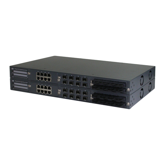
1.2 Product Panels The following figure illustrates the front panel and rear panel of the switch: Model Front Panel Rear Panel (Power Input) powered model powered model 1.3 Optional 8-port Modules Module Part No. Image Specifications 8 10/100/1000 copper ports ... - Page 12 4 10/100/1000 copper ports (4 RJ-45) support 10/100/1000Mbps 4 dual-speed SFP slots support standard 100M or 1000M SFP optical fiber transceivers 8 fixed 100M fiber ports 8FX-xxx 8 duplex SC transceivers support 100Mbps Options: MMF 2km, SMF 20km ...
-
Page 13: Optional Module Table
8 fixed 100M fiber ports 8FX-Wxxyy 8 BiDi SC transceivers support 100Mbps Options: Tx1310/Rx1550 SMF 20km Tx1550/Rx1310 SMF 20km 6 fixed 100M fiber ports with 6 8FM-Wxxyy BiDi SC transceivers support 100Mbps 2 10/100/1000 copper ports (2 RJ-45) ... -
Page 14: Led Indicators
1.4 LED Indicators Function Power status Mngt Management status 1000M Port speed 1000Mbps status Port link and activity status (Port 1 – Port 24) Link/Act. 25, 26 Port 25, Port 26 link and activity status 1.5 Specifications 10/100/1000 Copper Ports Compliance IEEE 802.3 10Base-T, IEEE 802.3u 100Base-TX, IEEE 802.3u 1000Base-T Connectors... - Page 15 10G SFP+ Slots Compliance IEEE 802.3 10GBASE SFP+ Connectors Dual-speed SFP+ slot supports optional both 1000BASE SFP and 10GBASE SFP+ type fiber transceivers, Direct Attach Cable (DAC) and Active Optical Cable (AOC) Configuration options Auto-negotiation 1000Mbps Full duplex, Auto-negotiation 10Gbps Full duplex (Software configurable) Auto-negotiation Flow control pause setting, Remote fault signaling...
- Page 16 DC Power Input (DC powered models) Interfaces Screw-type terminal block Operating Input Voltages +40 ~ +60VDC, -40 ~ -60VDC Power Consumption 48W max. Mechanical Dimension (base) 443 x 245 x 43 mm (WxDxH) Housing Enclosed metal Mounting Desktop mounting, 19” rack mounting Environmental Operating Temperature Typical -5 C ~ +50...
-
Page 17: Installation
2. Installation 2.1 Unpacking The product package contains: The switch unit One AC power cord (AC powered model) One 19” rack mounting kit 2.2 Safety Cautions To reduce the risk of bodily injury, electrical shock, fire and damage to the product, observe the following precautions. -
Page 18: Installing Module
2.3 Installing Module The steps to install a module are: 1. Unscrew and open the cover of the module slot. 2. Insert the module into the slot until it is plugged on the slot connector properly. 3. Screw the module on the front panel of the base chassis securely. -18-... -
Page 19: Removing The Module
2.4 Removing the Module The steps to remove an installed module from a base chassis are: 1. Unscrew the module first. 2. Loosen two screw brackets and pull them out as shown below: 3. Use the brackets as handles to pull the module out from the module slot connector. -19-... -
Page 20: Mounting The Switch
4. Remove the module from the slot. 2.5 Mounting the Switch Desktop Mounting The switch can be mounted on a desktop or shelf. Make sure that there is proper heat dissipation from and adequate ventilation around the device. Do not place heavy objects on the device. Rack Mounting Two 19-inch rack mounting brackets are supplied with the switch for 19-inch rack mounting. -
Page 21: Applying Ac Power Supply
2. Mount the switch onto 19-inch rack with rack screws securely. 3. Turn the power to the switch on. 2.6 Applying AC Power Supply If the purchased switch is with AC power input, one AC power cord which meets the specification of your country of origin was supplied in package. -
Page 22: Applying Dc Power Supply
AC power input specifications Connector: IEC320 type Power Rating: 100 ~ 240VAC, 50/60Hz Voltage Range: 90 ~ 264VAC Frequency: 47 ~ 63 Hz Power Consumption: 48W max. Important Notes: 1. The socket-outlet shall be installed near the switch and shall be easily accessible. 2. -
Page 23: Reset Button
3. The power wiring between the DC power supply and the switch must be stranded copper wire within the range of 10 to 24 AWG. 2.8 Reset Button The reset button is used to perform a reset to the switch. It is not used in normal cases and can be used for diagnostic purpose. -
Page 24: Making Utp Connections
2.9 Making UTP Connections The 10/100/1000 RJ-45 copper ports support the following connection types and distances: Network Cables 10BASE-T: 2-pair UTP Cat. 3, 4, 5, EIA/TIA-568B 100-ohm 100BASE-TX: 2-pair UTP Cat. 5, EIA/TIA-568B 100-ohm 1000BASE-T: 4-pair UTP Cat. 5 or higher (Cat.5e is recommended), EIA/TIA-568B 100-ohm Link distance: Up to 100 meters Auto MDI/MDI-X Function This function allows the port to auto-detect the twisted-pair signals and adapts itself to form a valid MDI to... -
Page 25: Making Fixed Duplex Fiber Connection
To install an SFP fiber transceiver into SFP slot, the steps are: 1. Turn off the power to the switch. 2. Insert the SFP fiber transceiver into the SFP slot. Normally, a bail is provided for every SFP transceiver. Hold the bail and make insertion. 3. - Page 26 A module with fixed duplex ST connectors is also available in the listed optional modules. Identify TX and RX connector before making cable connection. Plug in the cables as shown below. Make sure RX-to-TX connection rule is followed between two ends of the connected cable. -26-...
-
Page 27: Making Fixed Bi-Di (Bi-Directional) Fiber Connection
2.12 Making Fixed Bi-Di (Bi-Directional) Fiber Connection The following figure illustrates an example of fixed Bi-Di (Bi-directional) fiber port with one SC connector. A Bi-Di port supports single fiber connection. It uses different optical wavelengths for transmission and receiving individually as figure illustrated below: -27-... -
Page 28: Making 10G Sfp+ Connections
2.13 Making 10G SFP+ Connections The 10G SFP+ slot can support the following types of connection: 10GBASE-X SFP+ fiber transceivers 1000BASE-X SFP fiber transceivers Direct Attach Cable (DAC) Active Optical Cable (AOC) 10GBASE-X SFP Fiber Transceivers The following table lists the IEEE 802.3 standard 10GBASE specifications: Standard Wavelength... - Page 29 SFP+ Direct Attach Cable (DAC) DAC cables are made from copper and are factory terminated copper/twinax cables. DAC cables are used to connect switches, routers and servers. They’re assembled from shielded copper cables with a fixed length and are fitted with transceivers on either end of the cable with gauges attached. These can be from 24 up to 30 AWG, while 15 meters of interconnection is possible via the copper cable.
-
Page 30: Led Indication
2.14 LED Indication Function Color State Interpretation Power status Green ON The power is supplied to the switch. The power is not supplied to the switch. Mngt Management status Green OFF The switch is in initialization and diagnostics. BLINK The switch is initialized completely with diagnostic error. The switch is initialized completely and normal. -
Page 31: Making Console Connection
2.15 Making Console Connection Console port is a DB9 connector. It serves as an RS-232 DTE port. Pin Definitions Pin 2 Pin 3 Pin 5 Pin 1,4,6-9 NC Use RS232 null modem without handshaking to connect the console port to PC’s DB9 COM port as follows: Console Pins COM Port Pins Pin 2 RXD ----------------------------- Pin 3... -
Page 32: Managing The Switch
3. Managing the Switch The switch provides the following methods to configure and monitor the switch as follows: Making out of band management via RS-232 console port Making in-band management via telnet interface over TCP/IP network Making in-band management via web interface over TCP/IP network ... -
Page 33: Configuring Local Authentication Via Console And Telnet Cli
# configure terminal (config)# interface vlan 1 (config-if-vlan)# ip address dhcp fallback 192.168.4.171 255.255.255.0 Remark: 1. With factory default, vlan 1 is the only one that includes all switched ports as port members. 2. vlan 1 uses dhcp for IP configuration. 3. -
Page 34: Configuring Ip Address & Password Via Web Interface
3.4 Configuring IP Address & Password via Web Interface Start Web Browser Start your browser software and enter the default IP address to which you want to connect. The IP address is used as URL for the browser software to search the device. URL: http:/192.168.0.2/ Login to the switch When browser software connects to the switch successfully, a Login screen is provided for you to login to the... - Page 35 IP Address Configuration Select [Configuration] -> [System] -> [IP] to configure IP address for VLAN 1 Configuration Description IPv4 DHCP DHCP client configuration Enable Enable the DHCP client by checking this box. If this option is enabled, the system will configure the IPv4 address and mask of the interface using the DHCP protocol. Fallback The number of seconds for trying to obtain a DHCP lease.
- Page 36 User Configuration Select [Configuration] -> [Security] -> [Switch] -> [Users] to configure a new user, Michael as an example. Configuration Description User Name The name identifying the user. This is also a link to Add/Edit User interface. The privilege level of the user. The allowed range is 1 to 15. If the privilege level Privilege Level value is 15, it can access all groups, i.e.
- Page 37 Add New User Configuration Description User Name A string identifying the user name that this entry should belong to. The allowed string length is 1 to 31. The valid user name allows letters, numbers and underscores. The password of the user. The allowed string length is 0 to 31. Any printable Password characters including space are accepted.
-
Page 38: Reference Manuals For Web, Console, Telnet Management
admin Configure password for user Select [Configuration] -> [Security] -> [Switch] -> [Users] to show all users. Click admin to edit configuration. admin Edit user page to configure password for user: 3.5 Reference Manuals for Web, Console, Telnet Management The following operation manuals are also provided separately for Console, Telnet and Web management: Operation manual - telnet &... -
Page 39: Configuration For Snmp Management
3.6 Configuration for SNMP Management The switch supports SNMP v1, SNMP v2c, and SNMP v3 management. Make sure the related settings are well-configured for the switch before you start the SNMP management from an SNMP manager. Using Telnet CLI The following are available commands in telnet SNMP command group to configure SNMP-related settings: (config)# snmp-server ? access access configuration... - Page 40 Basic system configuration for SNMP v1, SNMP v2c and SNMP v3 Basic system configuration for SNMP v1 trap, SNMP v2c trap and SNMP v3 trap Communities that permit to access to SNMPv3 agent User table for SNMPv3 Group table for SNMPv3 Viewer table for SNMPv3 Accesses group table for SNMPv3 3.7 SNMP MIBs...
- Page 41 RADIUS accounting protocol. RFC 5519 - Multicast Group Membership MIB module for MGMD management Discovery (MGMD) MIB (Obsoletes RFC 2933 and RFC 3019 MIBs) MIB module for managing devices that support IEEE IEEE 802.1 MSTP MIB 802.1multiple spanning tree groups. IEEE 802.1AB LLDP MIB MIBs defined in 802.1AB.
Need help?
Do you have a question about the KGS-2422-TG Series and is the answer not in the manual?
Questions and answers