Table of Contents
Advertisement
Quick Links
Download this manual
See also:
User Manual
Advertisement
Table of Contents

Related Manuals for KTI Networks KGS-0820


Summary of Contents for KTI Networks KGS-0820
- Page 1 KGS-0820-C Managed 10-Port L2 Gigabit Ethernet Switches with 2 dual-speed SFP Slots and PoE option User s Manual DOC.131220...
- Page 2 (C) 2013 KTI Networks Inc. All rights reserved. No part of this documentation may be reproduced in any form or by any means or used to make any directive work (such as translation or transformation) without permission from KTI Networks Inc.
- Page 3 The information contained in this document is subject to change without prior notice. Copyright (C) All Rights Reserved. TRADEMARKS Ethernet is a registered trademark of Xerox Corp. FCC NOTICE This device complies with Part 15 of the FCC Rules. Operation is subject to the following two conditions: (1) This device may not cause harmful interference, and (2) This device must accept any interference received, including the interference that may cause undesired operation.
-
Page 4: Table Of Contents
Table of Contents 1. Introduction........................... 5 1.1 Features ........................ 5 1.2 Product Panels...................... 6 1.3 LED Indicators ...................... 7 1.4 Specifications ......................7 2. Installation........................... 10 2.1 Unpacking ......................10 2.2 Safety Cautions....................10 2.3 Mounting the Switch.................... 11 2.4 AC Power Supply ....................13 2.5 DC Power Supply.................... -
Page 5: Introduction
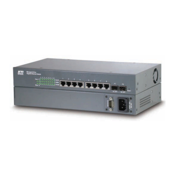
1. Introduction The KGS-0820-C is a managed Gigabit Ethernet switch which is featured with the following switched ports and advantages in a small footprint box: Eight 10/100/1000Mbps Gigabit copper ports Two dual-speed SFP slots for 100BASE-FX and 1000BASE-X transceivers... -
Page 6: Product Panels
Options with AC power and DC power 19” rack mountable Management Features Management: HTTP/HTTPS/SSHv2/CLI telnet/CLI console/SNMP v1/v2c/v3/RMON DHCP/DHCPv6 client, DHCP relay, DNS client. NTPv4 IPv6 support, System Syslog, Configuration down/upload, Software upload Security: NAS, 802.1X, MAC-based/Web/CLI authentication IP MAC binding, TACACS+, IP source guard ... -
Page 7: Led Indicators
Rear panel – Standard model Rear panel – “DC model” and “DC & PoE model” 1.3 LED Indicators Function Power Power status MNGT Management status Port 1~ 8 Upper LEDs Speed & PoE status Port 1~ 8 Lower LEDs Link & activity status Port 9, 10 LED Speed &... - Page 8 Dual-speed SFP Slots (Port 9, Port 10) Compliance IEEE 802.3u 100Base-FX IEEE 802.3z 1000Base-SX/LX (mini-GBIC) Connectors SFP for optional SFP type fiber transceivers Configuration Auto 1000Mbps, Full duplex Forced 100Mbps, Full duplex Transmission rate 100Mbps and 1000Mbps Network cables MMF 50/125 60/125, SMF 9/125 Eye safety IEC 825 compliant Console Port...
- Page 9 Interfaces IEC320 receptacle Operating Input Voltages 100 ~ 240VAC Power Consumption 11W max. @110VAC DC Power Input Interfaces Screw-type terminal block Operating Input Voltages +36 ~ +57VDC with No PoE support +45 ~ +57VDC for PoE support Power Consumption 13W max. (No PoE) 303W max.
-
Page 10: Installation
2. Installation 2.1 Unpacking The product package contains: The switch unit One AC power cord (AC model) One 19” rack mounting kit One product CD-ROM One RS-232 console cable 2.2 Safety Cautions To reduce the risk of bodily injury, electrical shock, fire and damage to the product, observe the following precautions. -
Page 11: Mounting The Switch
2.3 Mounting the Switch Desktop Mounting The switch can be mounted on a desktop or shelf. Make sure that there is proper heat dissipation from and adequate ventilation around the device. Do not place heavy objects on the device. Rack Mounting Two 19-inch rack mounting brackets are supplied with the switch for 19-inch rack mounting. - Page 12 4. Turn the power to the switch on. -12-...
-
Page 13: Ac Power Supply
2.4 AC Power Supply If the purchased switch is with AC power input, one AC power cord which meets the specification of your country of origin was supplied in package. Before installing AC power cord to the switch, make sure the AC power is OFF and the AC power to the power cord is turned off. -
Page 14: Dc Power Supply
2.5 DC Power Supply If the purchased switch is DC model or DC & PoE model, the power connector is shown below: DC power input specifications Receptacle: Screw-type terminal block Operating Voltages for PoE applications: +45 ~ +57VDC Operating Voltages for non-PoE applications: +36 ~ +57VDC DC Power Consumption 13W max. -
Page 15: Power Boot Up
2.6 Power Boot Up When powering the switch, the system starts initialization and diagnostic operations. The behavior sequence of the LED indicators are: LEDs Behavior Period & Indication MNGT-LED Green blink ~ 10 seconds All port LEDs Yellow ON ~ 3 seconds All port LEDs Green ON ~ 3 seconds... -
Page 16: Making Fiber Connection
MDI-X connection with the remote connected device automatically. No matter a straight through cable or crossover cable are connected, the ports can sense the receiving pair automatically and configure themselves to match the rule for MDI to MDI-X connection. It simplifies the cable installation. Auto-negotiation Function The ports are featured with auto-negotiation function and full capability to support connection to any Ethernet devices. - Page 17 Make sure the Rx-to-Tx connection rule is followed on the both ends of the fiber cable. Port Speed Configuration There are three options for configuring port speed via software for Port 9 and Port 10. The options are: Auto Auto-detection for the type of the installed SFP transceiver by reading DDM data 100Mbps transceiver: Non-auto-negotiation (forced), 100Mbps, full duplex 1000Mbps transceiver: Auto-negotiation, 1000Mbps, full duplex 100Mbps FDX...
-
Page 18: Making Poe Connections
2.10 Making PoE Connections This section describes how to make a connection between a PSE port and a PoE PD device. In Model DC & PoE, all copper ports are equipped with PoE PSE function. The ports are enabled to deliver power together with network signal to a connected powered device via Cat.5 cable. -
Page 19: Led Indication
2.11 LED Indication Function Color State Interpretation Power Power status Green The power is supplied to the switch. The power is not supplied to the switch. MNGT Management status Green The switch is in initialization and diagnostics. Yellow BLINK Initialization completed with diagnostic error or system error found during normal operation Green Initialization completed with no error... -
Page 20: Making Console Connection
2.12 Making Console Connection Console port is a 9-pin male D-sub connector. It serves as an RS-232 DTE port. Pin Definitions Pin 2 Pin 3 Pin 5 Pin 1,4,6-9 NC Baud Rate Information Baud rate: 115200 Data bits: 8 Parity: none Stop bit: 1 Flow control: disabled -20-... -
Page 21: Manage The Switch
3. Manage the Switch The switch provides the following methods to configure and monitor the switch as follows: Making out of band telnet CLI management via RS-232 console port Making in-band management via telnet CLI over TCP/IP network ... -
Page 22: Configuring Ip Address Via Web Interface
Parameters: <ipv6_addr> : IPv6 address is in 128-bit records represented as eight fields of up to four hexadecimal digits with a colon separates each field (:). <ipv6_prefix> : IPv6 subnet mask <ipv6_router> : IPv6 router [Password] setting command is also in Security/Switch/Users command group. Security Switch Users Configuration Security Switch Users Add <user_name>... - Page 23 No password is required. Click to login into the switch. Web Page after a Successful Login Select [Configuration] -> [System] -> [IP] to configure IP address Configuration Description -23-...
-
Page 24: Reference Manuals For Web, Console, Telnet Management
DHCP Client Enable the DHCP client by checking this box. IP Address Provide the IP address of this switch unit. IP Mask Provide the IP mask of this switch unit. IP Router Provide the IP address of the default router for this switch unit. VLAN ID Provide the managed VLAN ID. -
Page 25: Configuration For Snmp Management
3.5 Configuration for SNMP Management The switch supports SNMP v1, SNMP v2c, and SNMP v3 management. Make sure the related settings are well-configured for the switch before you start the SNMP management from an SNMP manager. Using Telnet Interface The following are available commands in telnet SNMP command group to configure SNMP-related settings: >SNMP Configuration >SNMP Mode [enable|disable] >SNMP Version [1|2c|3]... -
Page 26: Snmp Mibs
>SNMP View Delete <index> >SNMP View Lookup [<index>] >SNMP Access Add <group_name> <security_model> <security_level> [<read_view_name>] [<write_view_name>] >SNMP Access Delete <index> >SNMP Access Lookup [<index>] Using Web Interface The commands supports configuration for: Basic system configuration for SNMP v1 and SNMP v2c Basic system configuration for SNMP v1 trap, SNMP v2c trap and SNMP v3 trap Communities that permit to access to SNMPv3 agent USM (User-based Security Model) user table for SNMPv3... - Page 27 - RFC 4668 - RADIUS Authentication Client MIB - RFC 5519 - Multicast Group Membership Discovery (MGMD) MIB - IEEE 802.1 MSTP MIB - IEEE 802.1AB LLDP MIB - IEEE 802.1X Port Access Entity (PAE) MIB - TIA 1057 LLDP Media Endpoint Discovery (MED) MIB - IEEE 802.1-Q-BRIDGE MIB - Private SFPDDM MIB One product MIB file is also available in the product CD for SNMP manager software.
Need help?
Do you have a question about the KGS-0820 and is the answer not in the manual?
Questions and answers