
Related Manuals for KTI Networks KGS-1060


Summary of Contents for KTI Networks KGS-1060
- Page 1 KGS-1060 KGS-1060-HP Industrial Managed 10-Port Gigabit Ethernet Switches with 2 Dual-speed SFP Slots and 4 PoE PSE Ports Firmware Rev1.05 up User’s Manual DOC.150608...
- Page 2 (such as translation or transformation) without permission from KTI Networks Inc. KTI Networks Inc. reserves the right to revise this documentation and to make changes in content from time to time without obligation on the part of KTI Networks Inc. to provide notification of such revision or change.
- Page 3 The information contained in this document is subject to change without prior notice. © Copyright All Rights Reserved. TRADEMARKS Ethernet is a registered trademark of Xerox Corp. FCC NOTICE This device complies with Part 15 of the FCC Rules. Operation is subject to the following two conditions: (1) This device may not cause harmful interference, and (2) This device must accept any interference received, including the interference that may cause undesired operation.
-
Page 4: Table Of Contents
2.4 Panel Mounting ........................14 2.5 Applying Power ........................16 2.6 Alarm Relay Output......................18 2.7 Powered via PoE over Cat.5 (KGS-1060)................18 2.8 Reset Button ........................19 2.9 Making UTP Connections ....................20 2.10 Making Fiber Connection ....................21 2.11 Making PoE PSE Connections (KGS-1060-HP) .............. -
Page 5: Introduction
1. Introduction The KGS-1060 series is an 10-portt industrial managed Gigabit Ethernet switch which is featured with the following switched ports: Eight 10/100/1000Mbps Gigabit copper ports Two dual-speed SFP slots for 100Base-FX 1000Base-X Model Definitions Model Copper SFP slots... -
Page 6: Features
1.1 Features Eight 10/100/1000Mbps RJ-45 and two dual-speed SFP slots All copper ports support auto-negotiation and auto-MDI/MDI-X detection. Two SFP slots support dual speed for 100BASE-FX and 1000BASE-X SFP transceivers. Full wire speed forwarding Supports 802.3x flow control for full-duplex and backpressure for half-duplex ... -
Page 7: Product Panels
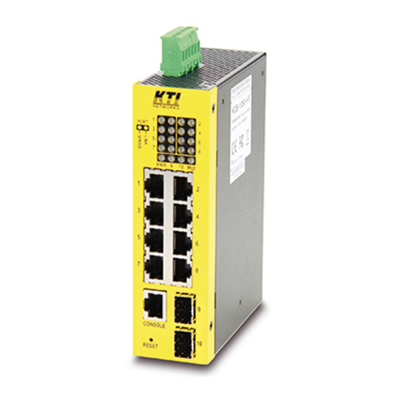
1.2 Product Panels The following figure illustrates the front panel and rear panel of the switch: KGS-1060-HP Front panel KGS-1060 Front panel... -
Page 8: Led Indicators
Up panel 1.3 LED Indicators Function Power status Mgt. Management status Port 1~ 8 SPEED LEDs Speed & PoE status Port 1~ 8 LINK LEDs Link & activity status SFP 9, 10 LED Speed & link & activity status of SFP port 1.4 Specifications 10/100/1000 Copper Ports (Port 1 ~ Port 8) Compliance... - Page 9 8192 supported Flow control IEEE 802.3x pause frame base for full duplex operation Back pressure for half duplex operation Power over Ethernet PSE Function (KGS-1060-HP) PSE Ports Port 1 ~ Port 4 Power output pins Positive of power voltage: pin 1,2...
- Page 10 DC power input Screwed euro terminal block: 2 pairs of +/- contacts Operating Input Voltages +7 ~ +60VDC (General applications) +45 ~ +57VDC (PoE applications) Power consumption 9W max. (Full load with no PoE support) 150W max. (Full load with 4 PoE max. output) Alarm relay output 2 terminal contacts AR+/AR- (30VDC/1A max.
-
Page 11: Installation
2. Installation 2.1 Unpacking The product package contains: The switch unit One product CD-ROM One console cable 2.2 Safety Cautions To reduce the risk of bodily injury, electrical shock, fire, and damage to the product, observe the following precautions. -
Page 12: Din-Rail Mounting
2.3 DIN-Rail Mounting In the product package, a DIN-rail bracket is provided for mounting the switch in a industrial DIN-rail enclosure. The steps to mount the switch onto a DIN rail are: 1. Install the mounting bracket onto the switch unit as shown below: 2. - Page 13 Dimensions: -13-...
-
Page 14: Panel Mounting
2.4 Panel Mounting The switches are provided with an optional panel mounting bracket. The bracket supports mounting the switch on a plane surface securely. The mounting steps are: 1. Install the mounting bracket on the switch unit. 2. Screw the bracket on the switch unit. 3. - Page 15 Dimensions: -15-...
-
Page 16: Applying Power
2.5 Applying Power Pin Assignments of the terminal block connector Vdc Positive ( ) input terminal Vdc Negative ( ) input terminal Vdc Positive ( ) input terminal Vdc Negative ( ) input terminal Alarm relay output positive () terminal ... - Page 17 Power wires : 24 ~ 12AWG (IEC 0.5~2.5mm Install the power source wires with the plug properly. Then, plug in input contacts. If cascading the power to next switch device is needed, install the power wires and plug for another switch. Then, use another Vdc contacts.
-
Page 18: Alarm Relay Output
Note: Be sure the voltage applied on AR+/- contacts is within the specification of 30VDC/1A max. or 120VAC/0.5A max. 2.7 Powered via PoE over Cat.5 (KGS-1060) Port 2 is equipped with function of receiving power from connected PoE PSE device over Cat.5 cable. The remote PoE PSE devices can be a mid-span PoE injector or end-span PoE switched port. -
Page 19: Reset Button
The switches can support the following PSE: 802.3af compliant PSE (Typical, Type 1 PSE) Possible voltages received: +36 ~ +57VDC 802.3at compliant PSE (High power PoE, Type 2 PSE) Possible voltages received: +42.5 ~ +57VDC 2.8 Reset Button The reset button is used to perform a reset to the switch. -
Page 20: Making Utp Connections
2.9 Making UTP Connections The 10/100/1000 RJ-45 copper ports support the following connection types and distances: Network Cables 10BASE-T: 2-pair UTP Cat. 3, 4, 5 , EIA/TIA-568B 100-ohm 100BASE-TX: 2-pair UTP Cat. 5, EIA/TIA-568B 100-ohm 1000BASE-T: 4-pair UTP Cat. 5 or higher (Cat.5e is recommended), EIA/TIA-568B 100-ohm Link distance: Up to 100 meters for all above Auto MDI/MDI-X Function... -
Page 21: Making Fiber Connection
2.10 Making Fiber Connection The dual-speed SFP slots, Port 9 and Port 10 must be installed with an SFP fiber transceiver for making fiber connection. Your switch may come with one or two SFP transceivers pre-installed when it is shipped. Types of the SFP Fiber transceivers supported: 1000Mbps based 1000BASE-X SFP transceivers 100Mbps based 100BASE-FX SFP transceivers... - Page 22 Network Cables Multimode (MMF) - 50/125, 62.5/125 Single mode (SMF) - 9/125 Port Speed Configuration There are three options for configuring port speed via software for SFP Port 9 and Port 10. The options are: Auto Auto-detection for the type of the installed SFP transceiver by reading DDM data 100Mbps transceiver: Non-auto-negotiation (forced), 100Mbps, full duplex 1000Mbps transceiver: Auto-negotiation, 1000Mbps, full duplex 100Mbps FDX...
-
Page 23: Making Poe Pse Connections (Kgs-1060-Hp)
2.11 Making PoE PSE Connections (KGS-1060-HP) This section describes how to make a connection between a PSE port and a PoE PD device. In Model DC & PoE, all copper ports are equipped with PoE PSE function. The ports are enabled to deliver power together with network signal to a connected powered device via Cat.5 cable. -
Page 24: Led Indication
2.12 LED Indication Function Color State Interpretation Power status Green The power is supplied to the switch. The power is not supplied to the switch. Mgt. Management status Green The switch is in initialization and diagnostics. Yellow BLINK Initialization completed with diagnostic error or system error found during normal operation Green Initialization completed with no error... - Page 25 Pin Assignments RS-232 signals IN/OUT 1,2,7,8 Baud Rate information Baud rate - 115200 Data bits - 8 Parity - None Stop bit - 1 Flow control – None -25-...
-
Page 26: Manage The Switch
3. Manage the Switch The switch provides the following methods to configure and monitor the switch as follows: Making out of band telnet CLI management via the console port Making in-band management via telnet CLI over TCP/IP network ... -
Page 27: Configuring Ip Address Via Web Interface
Parameters: <ipv6_addr> : IPv6 address is in 128-bit records represented as eight fields of up to four hexadecimal digits with a colon separates each field (:). <ipv6_prefix> : IPv6 subnet mask <ipv6_router> : IPv6 router [Password] setting command is also in Security/Switch/Users command group. Security Switch Users Configuration Security Switch Users Add <user_name>... - Page 28 No password is required. Click to login into the switch. Web Page after a Successful Login Select [Configuration] -> [System] -> [IP] to configure IP address -28-...
-
Page 29: Reference Manuals For Web, Console, Telnet Management
Configuration Description DHCP Client Enable the DHCP client by checking this box. IP Address Provide the IP address of this switch unit. IP Mask Provide the IP mask of this switch unit. IP Router Provide the IP address of the default router for this switch unit. Provide the managed VLAN ID. -
Page 30: Configuration For Snmp Management
3.5 Configuration for SNMP Management The switch supports SNMP v1, SNMP v2c, and SNMP v3 management. Make sure the related settings are well-configured for the switch before you start the SNMP management from an SNMP manager. Using Telnet Interface The following are available commands in telnet SNMP command group to configure SNMP-related settings: >SNMP Configuration >SNMP Mode [enable|disable] >SNMP Version [1|2c|3]... -
Page 31: Snmp Mibs
>SNMP View Delete <index> >SNMP View Lookup [<index>] >SNMP Access Add <group_name> <security_model> <security_level> [<read_view_name>] [<write_view_name>] >SNMP Access Delete <index> >SNMP Access Lookup [<index>] Using Web Interface The commands supports configuration for: Basic system configuration for SNMP v1 and SNMP v2c Basic system configuration for SNMP v1 trap, SNMP v2c trap and SNMP v3 trap Communities that permit to access to SNMPv3 agent USM (User-based Security Model) user table for SNMPv3... - Page 32 - RFC 4668 - RADIUS Authentication Client MIB - RFC 5519 - Multicast Group Membership Discovery (MGMD) MIB - IEEE 802.1 MSTP MIB - IEEE 802.1AB LLDP MIB - IEEE 802.1X Port Access Entity (PAE) MIB - TIA 1057 LLDP Media Endpoint Discovery (MED) MIB - IEEE 802.1-Q-BRIDGE MIB - Private SFPDDM MIB (DDM status) - Private reboot MIB (Remote boot over SNMP)
-
Page 33: Redundant Ring Applications
4. Redundant Ring Applications 4.1 Auto Multi-Ring Technology Auto Multi-Ring Technology was developed especially for switches connected in ring topology which needs redundant support when any failure occurs in ring. For large network, more than one ring connections are very common. Auto Multi-Ring Technology implementation can support more than one ring connection within a switch. -
Page 34: Redundant Ring Applications With Industrial Standard Rstp Protocol
The following figure shows one switch is configured to support three redundant rings and one RSTP ring at the same time. 4.2 Redundant Ring Applications with industrial standard RSTP protocol It also can be done to support a ring connection using industrial standard RSTP function and establish a backup path.
Need help?
Do you have a question about the KGS-1060 and is the answer not in the manual?
Questions and answers