Table of Contents
Advertisement
Quick Links
Download this manual
See also:
Installation Manual
Advertisement
Table of Contents

Related Manuals for KTI Networks KGS-2421


Summary of Contents for KTI Networks KGS-2421
- Page 1 KGS-2421 KGS-1620 Web Management Interface User s Manual DOC.110616...
- Page 2 Vitesse switch products. (C) 2010 KTI Networks Inc. All rights reserved. No part of this documentation may be reproduced in any form or by any means or used to make any directive work (such as translation or transformation) without permission...
- Page 3 KTI Networks Inc. reserves the right to revise this documentation and to make changes in content from time to time without obligation on the part of KTI Networks Inc. to provide notification of such revision or change. For more information, contact: United States KTI Networks Inc.
-
Page 4: Table Of Contents
Table of Contents 1. Web Management ............................8 1.1 Start Browser Software and Making Connection ............... 8 1.2 Login to the Switch Unit ..................... 8 1.3 Main Management Menu ....................10 2. Configuration ............................12 2.1 System ..........................12 2.1.1 Information ........................12 2.1.2 IP &... - Page 5 2.4.2 LACP..........................41 2.5 Spanning Tree ......................... 43 2.5.1 Bridge Settings......................43 2.5.2 MSTI Mapping....................... 45 2.5.3 MSTI Priorities ......................46 2.5.4 CIST Ports ........................47 2.5.5 MSTI Ports ........................48 2.6 IGMP Snooping........................ 51 2.6.1 Basic Configuration ....................... 51 2.6.2 VLAN Configuration ......................
- Page 6 3. Monitor ..............................86 3.1 System ..........................86 3.1.1 Information ........................86 3.1.2 CPU Load ........................87 3.1.3 Log ..........................88 3.1.4 Detailed Log ........................89 3.2 Ports..........................90 3.2.1 State..........................90 3.2.2 Traffic Overview ......................91 3.2.3 QoS Statistics ....................... 93 3.2.4 Detailed Statistics......................
- Page 7 3.7 LLDP ..........................114 3.7.1 Neighbors........................114 3.7.2 LLDP-MED Neighbors....................115 3.7.3 Port Statistics ......................118 3.8 MAC Table ........................120 3.9 VLAN..........................121 3.9.1 VLAN Membership ...................... 121 3.9.2 VLAN Port ........................122 4. Diagnostics ............................. 124 4.1 SFP DDM ........................124 4.2 Ping..........................
-
Page 8: Web Management
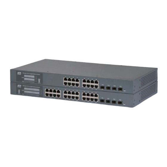
1. Web Management The switch features an http server which can serve the management requests coming from any web browser software over TCP/IP network. Web Browser Compatible web browser software with JAVA script support Microsoft Internet Explorer 4.0 or later Netscape Communicator 4.x or later Set IP Address for the System Unit Before the switch can be managed from a web browser software, make sure a unique IP address is configured... - Page 9 The switch will accept more than one successful management connection at the same time. A switch image icon is displayed as follows after a successful login. The following example shows an image of a 24-port switch model. Image of 24-Port Switch Model Image of 16-Port Switch Model...
-
Page 10: Main Management Menu
1.3 Main Management Menu Main Menu: Sub-menus: Configuration System Switch information, IP configuration, SNTP setting, and Password setting Ports Port operation related configuration, frame size, and power saving control Security Switch & UI authentication configuration, Port access security control Aggregation Static and LACP port link aggregation related configuration... - Page 11 LLDP LLDP neighbors information, Port statistics MAC Table Display of MAC address table VLAN Display VLAN membership and VLAN port status Diagnostics SFP DDM information Ping ICMP ping utility Copper Cable Copper cable diagnostics for all copper ports Maintenance Reset Device Command to reboot the switch Factory Defaults Command to restore the switch with factory default settings...
-
Page 12: Configuration
2. Configuration 2.1 System 2.1.1 Information Configuration Description System Contact The textual identification of the contact person for this managed node, together with information on how to contact this person. The allowed string length is 0 to 255, and the allowed content is the ASCII characters from 32 to 126. System Name An administratively assigned name for this managed node. -
Page 13: Ip & Time
2. The system Name, Contact, and Location settings are also used as SNMP MIBs. 2.1.2 IP & Time Configuration Description DHCP Client Enable the DHCP client by checking this box. IP Address Provide the address of this switch unit. IP Mask Provide the mask of this switch unit. -
Page 14: Ports
2.2 Ports Configuration Description Port The port number associated to this configuration row Link The current link status is displayed graphically. Green indicates the link is up and red that it is down. Speed - Current Provides the current link speed of the port. Speed - Configured Select any available link speed for the given switch port. - Page 15 100Mbps HDX: selects fixed 100Mbps and half duplex 10Mbps FDX: selects fixed 10Mbps and full duplex 10Mbps HDX: selects fixed 10Mbps and half duplex Flow Control – Current Rx Whether pause frames on the port are obeyed Flow Control – Current Tx Whether pause frames on the port are transmitted Flow Control –...
-
Page 16: Security
2.3 Security 2.3.1 Switch 2.3.1.1 Password Configuration Description Old Password Enter the current system password. If this is incorrect, the new password will not be set. New Password New system password to be used Allowed string length is 0 to 31, and the allowed content is the ASCII characters from 32 to 126. -
Page 17: Auth Method
2.3.1.2 Auth Method Configuration Description Client Access method to the switch – telnet, ssh, web, console Authentication Method Authentication can be set to one of the following values: none: authentication is disabled and login is not possible. local: use the local user database on the switch for authentication. RADIUS: use a remote RADIUS server for authentication. -
Page 18: Ssh
2.3.1.3 SSH Configuration Description Mode Indicates the mode operation. Possible modes are: Enabled: Enable SSH mode operation. Disabled: Disable SSH mode operation. Save Click to save the changes. Reset Click to undo any changes made locally and revert to previously saved values. -18-... -
Page 19: Https
2.3.1.4 HTTPS Configuration Description Mode Indicates the HTTPS mode operation. Possible modes are: Enabled: Enable HTTPS mode operation. Disabled: Disable HTTPS mode operation. Automatic Redirect Indicates the HTTPS redirect mode operation. Automatic redirect web browser to HTTPS during HTTPS mode enabled. Possible modes are: Enabled: Enable HTTPS redirect mode operation. -
Page 20: Snmp
2.3.1.5 SNMP 2.3.1.5.1 System System Configuration Description Mode Indicates the SNMP mode operation. Possible modes are: Enabled: Enable SNMP mode operation. Disabled: Disable SNMP mode operation. Version Indicates the SNMP supported version. Possible versions are: SNMP v1: Set SNMP supported version 1. -20-... - Page 21 SNMP v2c: Set SNMP supported version 2c. SNMP v3: Set SNMP supported version 3. Read Community Indicates the community read access string to permit access to SNMP agent. The allowed string length is 0 ~ 255, and the allowed content is the ASCII characters from 33 to 126.
- Page 22 separates each field (:). For example, 'fe80::215:c5ff:fe03:4dc7'. The symbol '::' is a special syntax that can be used as a shorthand way of representing multiple 16-bit groups of contiguous zeros; but it can only appear once. It also used a following legally IPv4 address.
-
Page 23: Communities
2.3.1.5.2 Communities Configuration Description Delete Check to delete the entry. It will be deleted during the next save. Community Indicates the community access string to permit access to SNMPv3 agent. The allowed string length is 1 to 32, and the allowed content is the ASCII characters from 33 to 126. -
Page 24: Users
2.3.1.5.3 Users Configuration Description Delete Check to delete the entry. It will be deleted during the next save. Engine ID An octet string identifying the engine ID that this entry should belong to. The string must contain an even number between 10 and 64 hexadecimal digits, but all-zeros and all-'F's are not allowed. - Page 25 the allowed string length is 8 to 32. For SHA authentication protocol, the allowed string length is 8 to 40. The allowed content is the ASCII characters from 33 to 126. Privacy Protocol Indicates the privacy protocol that this entry should belong to. Possible privacy protocols are: None: None privacy protocol.
-
Page 26: Groups
2.3.1.5.4 Groups Configuration Description Delete Check to delete the entry. It will be deleted during the next save. Security Model Indicates the security model that this entry should belong to. Possible security models are: v1: Reserved for SNMPv1. v2c: Reserved for SNMPv2c. usm: User-based Security Model (USM). -
Page 27: Views
2.3.1.5.5 Views Configuration Description Delete Check to delete the entry. It will be deleted during the next save. View Name A string identifying the view name that this entry should belong to. The allowed string length is 1 to 32, and the allowed content is the ASCII characters from 33 to 126. -
Page 28: Accesses
2.3.1.5.6 Accesses Configuration Description Delete Check to delete the entry. It will be deleted during the next save. Group Name A string identifying the group name that this entry should belong to. The allowed string length is 1 to 32, and the allowed content is the ASCII characters from 33 to 126. -
Page 29: Network
2.3.2 Network 2.3.2.1 NAS This page allows you to configure the IEEE 802.1X and MAC-based authentication system and port settings. The IEEE 802.1X standard defines a port-based access control procedure that prevents unauthorized access to a network by requiring users to first submit credentials for authentication. One or more central servers, the backend servers, determine whether the user is allowed access to the network. - Page 30 System Configuration Description Mode Indicates if 802.1X and MAC-based authentication is globally enabled or disabled on the switch unit. If globally disabled, all ports are allowed forwarding of frames. Reauthentication Enabled If checked, clients are re-authenticated after the interval specified by the Reauthentication Period.
- Page 31 EAPOL Timeout Determines the time the switch shall wait for the supplicant response before retransmitting a packet. Valid values: 1 ~ 255 seconds (This has no effect for MAC-based ports.) Age Period This setting applies to ports running MAC-based authentication, only. Suppose a client is connected to a 3 party switch or hub, which in turn is connected to a port on this switch that runs MAC-based authentication, and suppose the client...
- Page 32 switch transmits an EAPOL Failure frame when the port links up. MAC-Based: Enables MAC-based authentication on the port. The switch doesn’t transmit or accept EAPOL frames on the port. Flooded frames and broadcast traffic will be transmitted on the port, whether or not clients are authenticated on the port, whereas unicast traffic against an unsuccessfully authenticated client will be dropped.
-
Page 33: Acl
2.3.2.2 ACL 2.3.2.2.1 Ports Configure the parameters (ACE) of each switch port. These parameters will affect frames received on a port unless the frame matches a specific ACE. Configuration Description Port The logical port for the settings contained in the same row. Policy ID Select the policy to apply to this port. -
Page 34: Rate Limiters
Disabled: Port shut down is disabled. The default value is "Disabled". Counter Counts the number of frames that match this ACE. Save Click to save the changes. Reset Click to undo any changes made locally and revert to previously saved values. Refresh Click to refresh the page;... -
Page 35: Access Control Lists
2.3.2.2.3 Access Control Lists Configuration Description Ingress Port Indicates the ingress port of the ACE. Possible values are: Any: The ACE will match any ingress port. Policy: The ACE will match ingress ports with a specific policy. Port: The ACE will match a specific ingress port. Frame Type Indicates the frame type of the ACE. - Page 36 Counter The counter indicates the number of times the ACE was hit by a frame. Auto-refresh Check this box to refresh the page automatically. Automatic refresh occurs at regular intervals. ACE modification buttons: Inserts a new ACE before the current row. Edits the ACE.
-
Page 37: Auth Server
2.3.3 Auth Server Common Server Description Timeout The Timeout, which can be set to a number between 3 and 3600 seconds, is the maximum time to wait for a reply from a server. If the server does not reply within this timeframe, we will consider it to be dead and continue with the next enabled server (if any). - Page 38 Enabled Enable the RADIUS Authentication Server by checking this box. IP Address The IP address of the RADIUS Authentication Server expressed in dotted decimal notation. Port port to use on the RADIUS Authentication Server. If the port is set to zero (0), the default port (1812) is used for the RADIUS Authentication Server.
-
Page 39: Aggregation
2.4 Aggregation The Port Link Aggregation function can combine multiple physical switched ports, called “Aggregation Group” into one logical port. It allows making connection between two switches using more than one physical links to increase the connection bandwidth between two switches. Two aggregation modes, “Static” and “LACP”... - Page 40 Screen of 16-Port Switch Mode Configuration Description Source MAC Address The Source MAC address can be used to calculate the destination port for the frame. Check to enable the use of the Source MAC address, or uncheck to disable. By default, Source MAC Address is enabled.
-
Page 41: Lacp
Group ID Indicates the group ID for the settings contained in the same row. Group ID “Normal” indicates there is no aggregation. Only one group ID is valid per port. Port Members Each switch port is listed for each group ID. Select a radio button to include a port in an aggregation, or clear the radio button to remove the port from the aggregation. - Page 42 Auto: set the key as appropriate by the physical link speed, 10Mb = 1, 100Mb = 2, 1Gb = 3. Specific: a user-defined value can be entered. Ports with the same Key value can participate in the same aggregation group, while ports with different keys cannot. Role The Role shows the LACP activity status.
-
Page 43: Spanning Tree
2.5 Spanning Tree This section is used to set configuration for supporting Spanning Tree protocols including STP, RSTP, and MSTP. 2.5.1 Bridge Settings Basic Configuration Description Protocol Version protocol version setting Valid values: STP, RSTP, MSTP Forward Delay The delay used by STP Bridges to transition Root and Designated Ports to Forwarding (used in STP compatible mode). - Page 44 defines the initial value of remaining Hops for MSTI information generated at the boundary of an MSTI region. Transmit Hold Count The number of BPDU’s a bridge port can send per second. When exceeded, transmission of the next BPDU will be delayed. Valid values: 1 ~ 10 BPDU’s per second Advanced Configuration Edge Port BPDU Filtering Check to configure a port explicitly as Edge will transmit and receive BPDUs...
-
Page 45: Msti Mapping
2.5.2 MSTI Mapping Configuration Description Configuration Name The name identifying the VLAN to MSTI mapping Bridges must share the name and revision (see below), as well as the VLAN-to-MSTI mapping configuration in order to share spanning trees for MSTI’s. (Intra-region) The name is at most 32 characters. -
Page 46: Msti Priorities
Save Click to save the changes. Reset Click to undo any changes made locally and revert to previously saved values. 2.5.3 MSTI Priorities Configuration Description MSTI The bridge instance. The CIST is the default instance, which is always active. Priority Controls the bridge priority. -
Page 47: Cist Ports
2.5.4 CIST Ports Configuration Description Port The switch port number of the logical STP port. STP Enabled Controls whether STP is enabled on this switch port. Path Cost Controls the path cost incurred by the port. The Auto setting will set the path cost as appropriate by the physical link speed, using the 802.1D recommended values. -
Page 48: Msti Ports
port. This allows operEdge to be derived from whether BPDU’s are received on the port or not. Restricted-Role If enabled, causes the port not to be selected as Root Port for the CIST or any MSTI, even if it has the best spanning tree priority vector. Such a port will be selected as an Alternate Port after the Root Port has been selected. - Page 49 Configuration Description MSTI Select an MSTI for pop-up configuration. Click to pop-up configuration page. -49-...
- Page 50 Configuration Description (Example with MSTI1) Port The switch port number of the corresponding STP CIST (and MSTI) port. Path Cost Controls the path cost incurred by the port. The Auto setting will set the path cost as appropriate by the physical link speed, using the 802.1D recommended values. Using the Specific setting, a user-defined value can be entered.
-
Page 51: Igmp Snooping
2.6 IGMP Snooping 2.6.1 Basic Configuration Global Configuration Description Snooping Enabled Enable the Global IGMP Snooping. Unregistered IPMC Flooding enabled Enable unregistered IPMC traffic flooding. Port Configuration Description Port The port number for which the row configuration applies -51-... -
Page 52: Vlan Configuration
Router Port Specify which ports act as router ports. A router port is a port on the Ethernet switch that leads towards the Layer 3 multicast device or IGMP querier. If an aggregation member port is selected as a router port, the whole aggregation will act as a router port. -
Page 53: Lldp
2.7 LLDP 2.7.1 LLDP Global Configuration Description Tx Interval The switch is periodically transmitting LLDP frames to its neighbors for having the network discovery information up-to-date. The interval between each LLDP frame is determined by the Tx Interval value. Valid values: 5 – 32768 seconds Tx Hold Each LLDP frame contains information about how long the information in the LLDP frame shall be considered valid. - Page 54 multiplied by Tx Interval seconds. Valid values: 2 – 10 times Tx Delay If some configuration is changed (e.g. the IP address) a new LLDP frame is transmitted, but the time between the LLDP frames will always be at least the value of Tx Delay seconds.
-
Page 55: Lldp-Med
2.7.2 LLDP-MED Configuration Description Fast start repeat count The number of times the fast start transmission is repeated. The recommended value is 4 times, giving that 4 LLDP frames with a 1 second interval will be transmitted, when a LLDP frame with new information is received. Coordinates Location -55-... - Page 56 Latitude Latitude SHOULD be normalized to within 0-90 degrees with a maximum of 4 digits. It is possible to specify the direction to either North of the equator or South of the equator. Longitude Longitude SHOULD be normalized to within 0-180 degrees with a maximum of 4 digits.
- Page 57 Street suffix Street suffix - Example: Ave, Platz House no. House number - Example: 21 House no. suffix House number suffix - Example: A, 1/2 Landmark Landmark or vanity address - Example: Columbia University Additional location info Additional location info - Example: South Wing Name Name (residence and office occupant) - Example: Flemming Jahn Zip code...
- Page 58 should not be advertised if all the same network policies apply as those advertised in the Voice application policy. 3. Guest Voice - support a separate 'limited feature-set' voice service for guest users and visitors with their own IP Telephony handsets and other similar appliances supporting interactive voice services.
- Page 59 Priority may specify one of eight priority levels (0 through 7), as defined by IEEE 802.1D-2004. A value of 0 represents use of the default priority as defined in IEEE 802.1D-2004. DSCP DSCP value to be used to provide Diffserv node behavior for the specified application type as defined in IETF RFC 2474.
- Page 60 3. Softphone Voice 4. Video Conferencing 5. Streaming Video 6. Control / Signaling (conditionally support a separate network policy for the media types above) A large network may support multiple VoIP policies across the entire organization, and different policies per application type.
-
Page 61: Mac Table
2.8 MAC Table Screen of 24-Port Switch -61-... - Page 62 Screen of 16-Port Switch By default, dynamic entries are removed from the MAC after 300 seconds. This removal is also called aging. Aging Configuration Description Disable Automatic Aging Check to disable aging for MAC address entries. Aging Time Configure aging time by entering a value here in seconds Valid values: 10 to 1000000 seconds Port MAC Table Learning Auto...
-
Page 63: Static Mac Address Configuration
Add new static entry Click to configure a new static MAC address entry in the table. Save Click to save the changes. Reset Click to undo any changes made locally and revert to previously saved values. 2.8.1 Static MAC Address Configuration Screen of 24-Port Switch Screen of 16-Port Switch Static MAC Table Configuration... -
Page 64: Vlans
2.9 VLANs Up to 64 VLANs are supported. This page allows for adding and deleting VLANs as well as adding and deleting port members of each VLAN. 2.9.1 VLAN Membership Screen of 24-Port Switch Screen of 16-Port Switch Configuration Description Start from VLAN ….. - Page 65 can be configured as needed. Refresh Click to refresh the page; any changes made locally will be undone. |<< Click to display the first page. >>| Click to display the last page. Save Click to save the changes. Reset Click to undo any changes made locally and revert to previously saved values. Adding a New VLAN entry Screen of 24-Port Switch Configuration...
-
Page 66: Vlan Port Configuration
sure the box is unchecked. By default, no ports are members, and all boxes are unchecked. Delete Click to delete the new VLAN row. Add new VLAN Click to add another new VLAN ID. Save Click to save the new VLAN row. Reset Click to undo any changes made locally and revert to previously saved values. - Page 67 disabled (no checkmark). Ingress Filtering Enable ingress filtering for a port by checking the box. This parameter affects VLAN ingress processing. If ingress filtering is enabled and the ingress port is not a member of the classified VLAN of the frame, the frame is discarded. By default, ingress filtering is disabled (no checkmark).
-
Page 68: Private Vlans
2.10 Private VLANs A Private VLAN is a VLAN which contains switched ports that are restricted, such that they can only communicate with a given "uplink", or called “Promiscuous port”. The restricted ports are called "Isolated ports". Each private VLAN typically contains many isolated ports, and a single uplink. The uplink will typically be a switched port (or link aggregation group) connected to a router, firewall, server, provider network, or similar central resource. -
Page 69: Pvlan Memberships
2.10.1 PVLAN Memberships Screen of 24-Port Switch Screen of 16-Port Switch Configuration Description Delete Check to delete a VLAN entry. The entry will be deleted on the switch unit during Private VLAN ID Indicates the ID of this particular private VLAN. Note: The allowed range for a private VLAN ID is the same as the switch port number range. - Page 70 Adding new Private VLAN Screen of 24-Port Switch Screen of 16-Port Switch Configuration Description Private VLAN ID See above. Port Members See above. Delete Click to delete the new private VLAN row. -70-...
-
Page 71: Port Isolation
2.10.2 Port Isolation Screen of 24-Port Switch Screen of 16-Port Switch A port member of a VLAN can be isolated to other isolated ports on Private VLAN. Configuration Description Port Numbers A check box is provided for each port of a private VLAN. When checked, set the port to be isolation port in a private VLAN. -
Page 72: Qos
2.11 QoS Frames can be classified by 4 different QoS classes: Low, Normal, Medium, and High. The classification is controlled by a that is assigned to each port. A QCL consists of an ordered list of up to 12 QCEs. Each QCE can be used to classify certain frames to a specific QoS class. This classification can be based on parameters such as VLAN ID, UDP/TCP port, IPv4/IPv6 DSCP Priority. -
Page 73: Ports
2.11.1 Ports Configuration Description Number of Classes Configure the number of traffic classes as "1", "2", or "4". The default value is "4". Ingress Configuration Port The logical port for the settings contained in the same row. Default Class Configure the default QoS class for the port, that is, the QoS class for frames not matching any of the QCEs in the QCL. -
Page 74: Qos Control List
- Low Weight of Low Class - Normal Weight of Normal Class - Medium Weight of Medium Class - High Weight of High Class Save Click to save the changes. Reset Click to undo any changes made locally and revert to previously saved values. 2.11.2 QoS Control List Configuration Description... - Page 75 frame. The following QCE types are supported: Ethernet Type: The Ethernet Type field. If frame is tagged, this is the Ethernet Type that follows the tag header. VLAN ID: VLAN ID. Only applicable if the frame is VLAN tagged. TCP/UDP Port: IPv4 TCP/UDP source/destination port. DSCP: IPv4 and IPv6 DSCP.
-
Page 76: Rate Limiters
2.11.3 Rate Limiters Configuration Description Port The logical port for the settings contained in the same row. Policer Enabled Enable or disable the port policer. The default value is "Disabled". Policer Rate Configure the rate for the port policer. The default value is "500". This value is restricted to 500-1000000 when the "Policer Unit"... -
Page 77: Storm Control
2.11.4 Storm Control There is a unicast storm rate control, multicast storm rate control, and a broadcast storm rate control. These only affect flooded frames, i.e. frames with a (VLAN ID, DMAC) pair not present on the MAC Address table. The rate is 2^n, where n is equal to or less than 15, or "No Limit". -
Page 78: Wizard
2.11.5 Wizard This handy wizard helps you set up a quickly. -78-... -
Page 79: Wizard - Port Policies
2.11.6 Wizard – Port Policies Screen of 24-Port Switch Screen of 16-Port Switch -79-... - Page 80 Configuration Description QCL ID Frames that hit this are set to match this specific QCL. Port Members A row of radio buttons for each port is displayed for each QCL ID. To include a port in a QCL member, click the radio button. Cancel Wizard Click to cancel the wizard.
-
Page 81: Wizard - Typical Network Application Rules
2.11.7 Wizard – Typical Network Application Rules Configuration Description Audio and Video Indicates the common servers that apply to the specific QCE . The common servers are: QuickTime 4 Server, MSN Messenger Phone, Yahoo Messenger Phone, Napster, Real Audio. Games Indicates the common games that apply to the specific QCE. -
Page 82: Wizard - Tos Precedence Mapping
2.11.8 Wizard – ToS Precedence Mapping This wizard is used to set up the traffic class mapping to the precedence part of (3 bits) when receiving IPv4/IPv6 packets. Configuration Description QCL ID Select the QCL ID to which this QCE applies. ToS Precedence Class Select a traffic class of Low, Normal, Medium, or High to apply to the QCE. -
Page 83: Wizard - Vlan Tag Priority Mapping
2.11.9 Wizard – VLAN Tag Priority Mapping Configuration Description QCL ID Select the QCL ID to which this QCE applies. VLAN Priority Class Select a traffic class of Low, Normal, Medium, or High to apply to the QCE. Cancel Wizard Click to cancel the wizard. -
Page 84: Mirroring
2.12 Mirroring To debug network problems, selected traffic can be copied, or mirrored, to a mirror port where a frame analyzer can be attached to analyze the frame flow. The traffic to be copied to the mirror port is selected as follows: All frames received on a given port (also known as ingress or source mirroring). - Page 85 Disabled: Neither frames transmitted nor frames received are mirrored. Enabled: Frames received and frames transmitted are mirrored to the mirror port. Save Click to save the changes. Reset Click to undo any changes made locally and revert to previously saved values. Note: For a given port, a frame is only transmitted once.
-
Page 86: Monitor
3. Monitor 3.1 System 3.1.1 Information Status Information Description Contact The system contact configured in Configuration | System | Information | System Contact. Name The system name configured in Configuration | System | Information | System Name. Location The system location configured in Configuration | System | Information | System Location. -
Page 87: Cpu Load
System Date The current (GMT) system time and date. The system time is obtained through the configured SNTP Server, if any. System Uptime The period of time the device has been operational. Switch ID The switch ID. Software Version The software version of the switch Software Date The date when the switch software was produced. -
Page 88: Log
3.1.3 Log Configuration Description The ID (>= 1) of the system log entry. Level The level of the system log entry. The following level types are supported: Info: Information level of the system log. Warning: Warning level of the system log. Error: Error level of the system log. -
Page 89: Detailed Log
3.1.4 Detailed Log Configuration Description The ID (>= 1) of the system log entry. Message The message of the system log entry. Auto-refresh Check this box to enable an automatic refresh of the page at regular intervals. Refresh Click to Updates the system log entries, starting from the current entry ID. Clear Flushes all system log entries. -
Page 90: Ports
3.2 Ports 3.2.1 State Screen of 24-Port Switch Screen of 16-Port Switch Configuration Description Port Icon Click the port icon to display its detailed statistics. Port 2 example: Auto-refresh Check this box to enable an automatic refresh of the page at regular intervals. Refresh Click to refresh the page;... -
Page 91: Traffic Overview
3.2.2 Traffic Overview Screen of 24-Port Switch Screen of 16-Port Switch Configuration Description Port The logical port for the settings contained in the same row. Packets The number of received and transmitted packets per port.\ Bytes The number of received and transmitted bytes per port -91-... - Page 92 Errors The number of frames received in error and the number of incomplete transmissions per port. Drops The number of frames discarded due to ingress or egress congestion. Filtered The number of received frames filtered by the forwarding process Receive/Transmit The number of received and transmitted packets per port.
-
Page 93: Qos Statistics
3.2.3 QoS Statistics Screen of 24-Port Switch Screen of 16-Port Switch Configuration Description Port The logical port for the settings contained in the same row. Low Queue There are 4 queues per port with strict or weighted queuing scheduling. This is the lowest priority queue. - Page 94 Normal Queue This is the normal priority queue of the 4 QoS queues. It has higher priority than the "Low Queue". Medium Queue This is the medium priority queue of the 4 QoS queues. It has higher priority than the "Normal Queue".
-
Page 95: Detailed Statistics
3.2.4 Detailed Statistics Configuration Description Receive Total and Transmit Total Rx and Tx Packets Number of received and transmitted (good and bad) packets. Rx and Tx Octets Number of received and transmitted (good and bad) bytes. Includes FCS, but excludes framing bits. Rx and Tx Unicast Number of received and transmitted (good and bad) unicast packets. - Page 96 Receive Error Counters Rx Drops Number of frames dropped due to lack of receive buffers or egress congestion. Rx CRC/Alignment Number of frames received with CRC or alignment errors. Rx Undersize Number of short frames received with valid CRC. Rx Oversize Number of long frames received with valid CRC.
-
Page 97: Security
3.3 Security 3.3.1 Network -97-... -
Page 98: Port Security
3.3.1.1 Port Security 3.3.1.1.1 Switch Configuration Description User Module Name The full name of a module that may request Port Security services. Abbr A one-letter abbreviation of the user module This is used in the Users column in the port status table. Port The port number for which the status applies. -
Page 99: Port
shown. Auto-refresh Check this box to enable an automatic refresh of the page at regular intervals. Refresh Click to refresh the page; any changes made locally will be undone. 3.3.1.1.2 Port Configuration Description Port # Select a port to display. MAC Address The MAC address and VLAN ID that is seen on this port. -
Page 100: Nas
3.3.1.2 NAS 3.3.1.2.1 Switch Configuration Description Port # Select a port to display. Auto-refresh Check this box to enable an automatic refresh of the page at regular intervals. Refresh Click to refresh the page; any changes made locally will be undone. 3.3.1.2.2 Port Configuration Description... -
Page 101: Acl Status
possible values. Port State The current state of the port. Refer to NAS Port State for a description of the individual states. Auto-refresh Check this box to enable an automatic refresh of the page at regular intervals. Refresh Click to refresh the page; any changes made locally will be undone. 3.3.1.3 ACL Status Configuration Description... -
Page 102: Auth Server
Forward packet that matched the specific ACE to CPU CPU Once Forward the first packet that matched the specific ACE to CPU. Counter The counter indicates the number of times the ACE was hit by a frame. Conflict Indicates the hardware status of the specific ACE. The specific ACE is not applied to the hardware due to hardware limitations. -
Page 103: Radius Details
is displayed in parentheses. This state is only reachable when more than one server is enabled. Auto-refresh Check this box to enable an automatic refresh of the page at regular intervals. Refresh Click to refresh the page; any changes made locally will be undone. 3.3.2.2 RADIUS Details Configuration Description... - Page 104 The number of RADIUS packets that were received from the server on the authentication port and dropped for some other reason. Packets Dropped RFC4670 name: radiusAuthClientExtPacketsDropped The number of RADIUS packets that were received from the server on the authentication port and dropped for some other reason. Access Requests RFC4670 name: radiusAuthClientExtAccessRequests The number of RADIUS Access-Request packets sent to the server.
-
Page 105: Lacp
Auto-refresh Check this box to enable an automatic refresh of the page at regular intervals. Refresh Click to refresh the page; any changes made locally will be undone. Clear Click to clear all counters. 3.4 LACP 3.4.1 System Status Configuration Description Aggr ID The Aggregation ID associated with this aggregation instance. -
Page 106: Port Status
3.4.2 Port Status Screen of 24-Port Switch -106-... - Page 107 Screen of 16-Port Switch Configuration Description Port The switch port number. LACP 'Yes' means that LACP is enabled and the port link is up. 'No' means that LACP is not enabled or that the port link is down. 'Backup' means that the port could not join the aggregation group but will join if other port leaves.
-
Page 108: Port Statistics
3.4.3 Port Statistics Configuration Description Port The switch port number. LACP Received Shows how many LACP frames have been received at each port. LACP Transmitted Shows how many LACP frames have been sent from each port. Discarded Shows how many unknown or illegal LACP frames have been discarded at each port. Auto-refresh Check this box to enable an automatic refresh of the page at regular intervals. -
Page 109: Spanning Tree
3.5 Spanning Tree 3.5.1 Bridge Status Configuration Description MSTI The Bridge Instance. This is also a link to the STP Detailed Bridge Status. Bridge ID The Bridge ID of this Bridge instance. Root ID The Bridge ID of the currently elected root bridge. Root Port The switch port currently assigned the root port role. - Page 110 Configuration Description Bridge Instance The Bridge instance - CIST, MST1, ... Bridge ID The Bridge ID of this Bridge instance. Root ID The Bridge ID of the currently elected root bridge. Root Port The switch port currently assigned the root port role. Root Cost Root Path Cost.
-
Page 111: Port Status
Role The current STP port role. The port role can be one of the following values: AlternatePort, BackupPort, RootPort, DesignatedPort. State The current STP port state. The port state can be one of the following values: Blocking, Learning, Forwarding. Path Cost The current STP port path cost. -
Page 112: Port Statistics
CIST Role The current STP port role of the CIST port. The port role can be one of the following values: AlternatePort, BackupPort, RootPort, DesignatedPort. CIST State The current STP port state of the CIST port. The port state can be one of the following values: Blocking, Learning, Forwarding. -
Page 113: Igmp Snooping
3.6 IGMP Snooping Status Description Statistics VLAN ID The VLAN ID of the entry. Querier Status Show the Querier status is "ACTIVE" or "IDLE". Querier Transmit The number of Transmitted Querier. Querier Receive The number of Received Querier. V1 Reports Receive The number of Received V1 Reports. -
Page 114: Lldp
Refresh Click to refresh the page; any changes made locally will be undone. Clear Click to clear all counters. 3.7 LLDP 3.7.1 Neighbors Status Description Local Port The port on which the LLDP frame was received. Chassis ID The Chassis ID is the identification of the neighbor's LLDP frames. Remote Port ID The Remote Port ID is the identification of the neighbor port. -
Page 115: Lldp-Med Neighbors
Refresh Click to refresh the page; any changes made locally will be undone. 3.7.2 LLDP-MED Neighbors Status Description Port The port on which the LLDP frame was received. Device Type LLDP-MED Devices are comprised of two primary Device Types: Network Connectivity Devices and Endpoint Devices. - Page 116 products that require the base LLDP discovery services defined in TIA-1057, however do not support IP media or act as an end-user communication appliance. Such devices may include (but are not limited to) IP Communication Controllers, other communication related servers, or any device requiring basic services as defined in TIA-1057.
- Page 117 7. Reserved Application Type Application Type indicating the primary function of the application(s) defined for this network policy, advertised by an Endpoint or Network Connectivity Device. The poosible application types are shown below. 1. Voice - for use by dedicated IP Telephony handsets and other similar appliances supporting interactive voice services.
-
Page 118: Port Statistics
802.1Q-2003, meaning that only the IEEE 802.1D priority level is significant and the default PVID of the ingress port is used instead. Priority Priority is the Layer 2 priority to be used for the specified application type.One of eight priority levels (0 through 7) DSCP DSCP is the DSCP value to be used to provide Diffserv node behavior for the specified application type as defined in IETF RFC 2474. - Page 119 Total Neighbors Entries Deleted Shows the number of new entries deleted since switch reboot. Total Neighbors Entries Dropped Shows the number of LLDP frames dropped due to that the entry table was full. Total Neighbors Entries Aged Out Shows the number of entries deleted due to Time-To-Live expiring. Local Counters Local Port The port on which LLDP frames are received or transmitted.
-
Page 120: Mac Table
3.8 MAC Table MAC Table Column Description Type Indicates whether the entry is a static or dynamic entry. MAC address The MAC address of the entry. VLAN The VLAN ID of the entry. Port Members The ports that are members of the entry. Auto-refresh Check this box to enable an automatic refresh of the page at regular intervals. -
Page 121: Vlan
3.9 VLAN 3.9.1 VLAN Membership A VLAN User is a module that uses services of the VLAN management functionality to configure VLAN memberships and VLAN port configuration such as PVID, UVID. Currently we support following VLAN: Static: CLI/Web/SNMP users NAS: NAS provides port-based authentication, which involves communications between a Supplicant, Authenticator, and an Authentication Server. -
Page 122: Vlan Port
3.9.2 VLAN Port Select a type of VLAN Users Status Description Port The logical port for the settings contained in the same row. Shows the VLAN identifier for that port. The allowed values are 1 through 4095. The PVID default value is 1. VLAN Aware Shows the VLAN Awareness for the port. - Page 123 requests to set VLAN membership or VLAN port configuration, the following conflicts can occur: 1. Functional Conflicts between feature. 2. Conflicts due to hardware limitation. 3. Direct conflict between user modules. -123-...
-
Page 124: Diagnostics
4. Diagnostics 4.1 SFP DDM Screen of 24-Port Switch Screen of 16-Port Switch Status Description SFP Ports Port numbers which are equipped with SFP slot (i.e. Port 21, 22, 23 and 24). Identifier Identification information of the transceiver Connector The connector type used on the transceiver SONET Compliance The SONET compliance information of the transceiver -124-... - Page 125 GbE Compliance Gigabit Ethernet compliance information of the transceiver Vendor Name The vendor name of the transceiver Vendor OUI The vendor OUI of the transceiver Temperature The current temperature sensed currently inside the transceiver Voltage The working voltage sensed currently inside the transceiver TX Power The transmission optical power sensed currently TX power data is displayed in unit of µW.
-
Page 126: Ping
4.2 Ping Settings Description IP Address The destination IP Address Ping Size Payload size of the ICMP packet. Values range: 8 ~ 1400 bytes. Start Click to start ping test. Five ICMP packets are transmitted, and the sequence number and roundtrip time are displayed upon reception of a reply. The page refreshes automatically until responses to all packets are received, or until a timeout occurs. -
Page 127: Copper Cable
4.3 Copper Cable Status Description Port The port where you are requesting Copper Cable Diagnostics. All: select all ports Cable Status Port: Port number. Pair: The status of the cable pair. Pair A, B, C, D Length: The length (in meters) of the cable pair. Start Click to run the diagnostics. -
Page 128: Maintenance
5. Maintenance 5.1 Reset Device You can reset the stack switch on this page. After reset, the system will boot normally as if you had powered-on the devices. Click to reboot device. “System rebooting” message is displayed as follows. Click to return to the Port State page without rebooting. -128-... -
Page 129: Factory Defaults
5.2 Factory Defaults Click to reboot device. “System rebooting” message is displayed as follows. Click to return to the Port State page without rebooting. 5.3 Software Upload This page facilitates an update of the firmware controlling the switch. Browse Click to the location of a software image Upload Click to start uploading. - Page 130 Save configuration Click to start download of the configuration. Browse Click to the location of a configuration file Upload Click to start uploading configuration. -130-...
-
Page 131: Glossary
Glossary C D E F L M N O P Q R S T U V W X Y Z is an acronym for Access Control Entry. It describes access permission associated with a particular ACE ID. There are three ACE frame types (Ethernet Type, ARP, and IPv4) and two ACE actions (permit and deny). - Page 132 past the ACE matching without getting matched. In that case a counter associated with that port is incremented. See the Web page help text for each specific port property. ACL|Rate Limiters: Under this page you can configure the rate limiters. There can be 15 different rate limiters, each ranging from 1-1024K packets per seconds.
- Page 133 MEP to it's peer MEP and used to implement functionality. is an acronym for Cisco Discovery Protocol. is an acronym for Digital Diagnostics Monitoring. Modern optical SFP transceivers support digital diagnostics monitoring (DDM) functions according to the industry-standard SFF-8472. This feature gives the end user the ability to monitor real-time parameters of the SFP, such as optical output power, optical input power, temperature, laser bias current, and transceiver supply voltage.
- Page 134 specific information from a DHCP reply packets when forwarding server DHCP packets to a DHCP client. The DHCP server can use this information to implement IP address or other assignment policies. Specifically the option works by setting two sub-options: Circuit ID (option 1) and Remote ID (option2).
- Page 135 Is an abbreviation for Ethernet Protection Switching defined in ITU/T G.8031. Ethernet Type Ethernet Type, or EtherType, is a field in the Ethernet MAC header, defined by the Ethernet networking standard. It is used to indicate which protocol is being transported in an Ethernet frame.
- Page 136 logons. HTTPS is really just the use of Netscape's Secure Socket Layer (SSL) as a sublayer under its regular HTTP application layering. (HTTPS uses port 443 instead of HTTP port 80 in its interactions with the lower layer, TCP/IP.) SSL uses a 40-bit key size for the RC4 stream encryption algorithm, which is considered an adequate degree of encryption for commercial exchange.
- Page 137 and then delete and expunge the messages from the server. is an acronym for Internet Protocol. It is a protocol used for communicating data across a internet network. IP is a "best effort" system, which means that no packet of information sent over it is assured to reach its destination in the same condition it was sent.
- Page 138 builds up a table that maps MAC addresses to switch ports for knowing which ports the frames should go to ( based upon the DMAC address in the frame ). This table contains both static and dynamic entries. The static entries are configured by the network administrator if the administrator wants to do a fixed mapping between the DMAC address and switch ports.
- Page 139 clocks of computer systems. NTP uses (datagrams) as transport layer. is an acronym for Operation Administration and Maintenance. It is a protocol described in ITU-T Y.1731 used to implement carrier Ethernet functionality. functionality like is based on this Optional TLVs. A LLDP frame contains multiple TLVs For some...
- Page 140 POP3 is designed to delete mail on the server as soon as the user has downloaded it. However, some implementations allow users or an administrator to specify that mail be saved for some period of time. POP can be thought of as a "store-and-forward" service. An alternative protocol is Internet Message Access Protocol (IMAP).
- Page 141 A communications network transports a multitude of applications and data, including high-quality video and delay-sensitive data such as real-time voice. Networks must provide secure, predictable, measurable, and sometimes guaranteed services. Achieving the required QoS becomes the secret to a successful end-to-end business solution. Therefore, QoS is the set of techniques to manage network resources.
- Page 142 device. RSTP In 1998, the IEEE with document 802.1w introduced an evolution of STP: the Rapid Spanning Tree Protocol, which provides for faster spanning tree convergence after a topology change. Standard IEEE 802.1D-2004 now incorporates RSTP and obsoletes STP, while at the same time being backwards-compatible with STP.
- Page 143 the clocks of computer systems. SNTP uses (datagrams) as transport layer. SPROUT Stack Protocol using ROUting Technology. An advanced protocol for almost instantaneous discovery of topology changes within a stack as well as election of a master switch. SPROUT also calculates parameters for setting up each switch to perform shortest path forwarding within the stack.
- Page 144 separate authentication, authorization and accounting services. Tag Priority Tag Priority is a 3-bit field storing the priority level for the 802.1Q frame. is an acronym for Transmission Control Protocol. It is a communications protocol that uses the Internet Protocol (IP) to exchange the messages between computers. The TCP protocol guarantees reliable and in-order delivery of data from sender to receiver and distinguishes data for multiple connections by concurrent applications (for example, Web server and e-mail server) running on the same host.
- Page 145 information. Each of these pieces of information is known as TLV. TKIP TKIP is an acronym for Temporal Key Integrity Protocol. It used in WPA to replace WEP with a new encryption algorithm. TKIP comprises the same encryption engine and RC4 algorithm defined for WEP.
- Page 146 aware. Ports connected to VLAN aware switches are members of multiple VLANs and transmit tagged frames. Other ports are members of one VLAN, set up with this Port VLAN ID, and transmit untagged frames. Provider switching: This is also known as Q-in-Q switching. Ports connected to subscribers are VLAN unaware, members of one VLAN, and set up with this unique Port VLAN ID.
- Page 147 a Draft 3 of the IEEE 802.11i standard (Wikipedia) WPA-Radius WPA-Radius is an acronym for Wi-Fi Protected Access - Radius (802.1X authentication server). WPA was designed to enhance the security of wireless networks. There are two flavors of WPA: enterprise and personal. Enterprise is meant for use with an IEEE 802.1X authentication server, which distributes different keys to each user.
Need help?
Do you have a question about the KGS-2421 and is the answer not in the manual?
Questions and answers