
Related Manuals for KTI Networks KGS-2423


Summary of Contents for KTI Networks KGS-2423
- Page 1 KGS-2423 Managed 24-Port Stackable Gigabit Ethernet Switches with 4 SFP Slots Installation Guide DOC.120405...
- Page 2 (C) 2012 KTI Networks Inc. All rights reserved. No part of this documentation may be reproduced in any form or by any means or used to make any directive work (such as translation or transformation) without permission from KTI Networks Inc.
- Page 3 The information contained in this document is subject to change without prior notice. Copyright (C) All Rights Reserved. TRADEMARKS Ethernet is a registered trademark of Xerox Corp. FCC NOTICE This device complies with Part 15 of the FCC Rules. Operation is subject to the following two conditions: (1) This device may not cause harmful interference, and (2) This device must accept any interference received, including the interference that may cause undesired operation.
-
Page 4: Table Of Contents
Table of Contents 1. Introduction..............................6 1.1 Features ..........................7 1.2 Product Panels........................9 1.3 LED Indicators ........................10 1.4 Specifications ........................10 2. Installation..............................13 2.1 Unpacking ..........................13 2.2 Safety Cautions........................13 2.3 Mounting the Switch......................14 2.4 Applying AC Power Supply ....................15 2.5 Applying DC Power Supply .................... - Page 5 3.4 Configuring IP Address via console and telnet ..............34 3.5 Reference Manuals for Web, Console, Telnet Management ..........35 3.6 Configuration for SNMP Management ................. 35 3.7 SNMP MIBs ......................... 37...
-
Page 6: Introduction
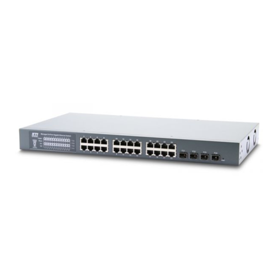
1. Introduction The managed 24-port Stackable Gigabit Ethernet Switches are standard L2 switches that meets all IEEE 802.3/u/x/z Gigabit, Fast Ethernet specifications. The switch has 20 10/100/1000Mbps copper ports and 4 combo ports with four additional Gigabit SFP slots. The SFP slots support standard SFP fiber optical transceivers for fiber optic application. -
Page 7: Features
KGS-2423-S AC powered model AC 100 ~ 240V √ KGS-2423-PS AC powered model with PoE AC 100 ~ 240V KGS-2423-D DC powered model DC +40 ~ 72V √ KGS-2423-PD DC powered model with PoE DC +40 ~ 72V 1.1 Features Provides 24 10/100/1000Mbps RJ-45 and four Gigabit SFP slots (4 combo ports) Provides optional 24 802.3af and 802.3at compliant PoE/PoE+ PSE ports... - Page 8 Provides SNMP v1/v2C/v3 agent and event trap function Supports Configuration download and upload Supports SFP with Digital Diagnostic Monitoring DDM support Supports Green Ethernet power saving Both AC powered model and DC powered model are available for choice Management Features: Port Control - Port Speed/Duplex Mode/Flow Control/Power saving configuration - Port frame size control (Jumbo frame support)
-
Page 9: Product Panels
- Restore to default configuration - Configuration download and upload - System syslog SNMP MIBs 1.2 Product Panels The following figure illustrates the front panel and rear panel of the switch: Front panel Rear panel AC powered model AC powered model with PoE... -
Page 10: Led Indicators
DC powered model DC powered model with PoE 1.3 LED Indicators Function POWER Power status Mngt Management status SA, SB Stack port status 1000M Port speed 1000Mbps status and PoE status (Port 1 – Port 24) Link/Act. Port link and activity status (Port 1 – Port 24) F21 –... - Page 11 Combo Ports (Port 21 ~ Port 24) with 10/100/1000 RJ-45 and 1000Mbps SFP 10/100/1000 Copper Port Interface Same as above 10/100/1000 Copper Ports Fiber interface Compliance IEEE 802.3z 1000Base-SX/LX (mini-GBIC) Connectors SFP slot for optional SFP type fiber transceivers Configuration Auto/Forced, 1000Mbps, Full duplex Transmission rate 1000Mbps...
- Page 12 DC Power Input (DC powered models) Interfaces Screw-type terminal block Operating Input Voltages +40 ~ +72VDC Power Consumption 39W max. (PoE power is excluded) PoE DC Power Input (PoE featured models) Interfaces Screw-type terminal block Operating Input Voltages +45 ~ +57VDC Mechanical Dimension (base) 443 x 245 x 43 mm (WxDxH)
-
Page 13: Installation
2. Installation 2.1 Unpacking The product package contains: The switch unit One AC power cord (AC powered Model) One 19” rack mounting kit One product CD-ROM 2.2 Safety Cautions To reduce the risk of bodily injury, electrical shock, fire and damage to the product, observe the following precautions. -
Page 14: Mounting The Switch
2.3 Mounting the Switch Desktop Mounting The switch can be mounted on a desktop or shelf. Make sure that there is proper heat dissipation from and adequate ventilation around the device. Do not place heavy objects on the device. Rack Mounting Two 19-inch rack mounting brackets are supplied with the switch for 19-inch rack mounting. -
Page 15: Applying Ac Power Supply
3. Turn the power to the switch on. 2.4 Applying AC Power Supply If the purchased switch is with AC power input, one AC power cord which meets the specification of your country of origin was supplied in package. Before installing AC power cord to the switch, make sure the AC power is OFF and the AC power to the power cord is turned off. -
Page 16: Reset Button
DC power input specifications Receptacle: Screw-type terminal block Operating Voltages: +40 ~ +72VDC Power Consumption: 39W max. @48VDC (PoE power is excluded) Contacts Vdc+ input Vdc- input Protective earth ** Important Notice For safety, a readily accessible disconnected device (breaker) shall be incorporated external to the equipment. 2.6 Reset Button The reset button is used to perform a reset to the switch. -
Page 17: Making Utp Connections
Operation Function Press the button during system boot-up and release Restore factory default settings it after boot-up. The boot-up takes about 17 seconds (only applicable to the master unit) and ends with LED diagnostics. Press the button and release during switch operation Re-boot the switch unit 2.7 Making UTP Connections The 10/100/1000 RJ-45 copper ports support the following connection types and distances:... - Page 18 come with some SFP transceivers pre-installed when it was shipped. Installing SFP Fiber Transceiver To install an SFP fiber transceiver into SFP slot, the steps are: 1. Turn off the power to the switch. 2. Insert the SFP fiber transceiver into the SFP slot. Normally, a bail is provided for every SFP transceiver. Hold the bail and make insertion.
-
Page 19: Using Power Over Ethernet
The following figure illustrates a connection example between two fiber ports: Make sure the Rx-to-Tx connection rule is followed on the both ends of the fiber cable. Network Cables Multimode (MMF) - 50/125μm, 62.5/125 μm Single mode (SMF) - 9/125 μm Fiber Port Configuration For 1000M fiber application on Port 21, 22, 23, and 24, just leave the default port configuration Auto for fiber connection. -
Page 20: Poe Power Output
Remark: IEEE 802.3af standard is often abbreviated as “PoE”. IEEE 802.3at PoE standard is also known as “PoE+” or “PoE plus”. PoE DC IN Contacts Vpoe+ input Vpoe- input Chassis ground for connecting earth 2.9.2 PoE Power Output PoE power on Port RJ-45 jack Pin 4,5 Vpoe+ pins Pin 7,8... -
Page 21: Making Stack Connection
PD Short circuit* PoE Shut down immediately Remark: *1. The detected PD load is over class allocation or user demand configuration. *2. The detected port current is over the max. limit current. 2.10 Making Stack Connection To expand the number of the connected users, the switch provides two 5G stack ports for cascading more than one switch together. - Page 22 To make stack connection in a switch stack, the steps are: 1. Follow the connection rule of “SA to SB” from one switch to another. 2. Connect all switches in the stack sequentially via stack cables. 3. Make sure all SA-to-SB connections become a loop as illustrated in the following figure: -22-...
-
Page 23: Led Indication
2.11 LED Indication Function Color State Interpretation POWER Power status Green ON The power is supplied to the switch. The power is not supplied to the switch. Mngt Management status Green OFF The switch is in initialization and diagnostics. BLINK The switch is initialized completely with diagnostic error. The switch is initialized completely and normal. -
Page 24: Making Console Connection
SFP fiber connection is selected on Port 23. Port F24 status Green OFF RJ-45 copper connection is selected on Port 24. SFP fiber connection is selected on Port 24. 2.12 Making Console Connection Console port is a DB9 connector. It serves as an RS-232 DTE port. Pin Definitions Pin 2 Pin 3... -
Page 25: Managing The Switch Stack
3. Managing the Switch Stack The switch stack provides the following methods to configure and monitor the switch stack as follows: Making out of band management via RS-232 console port Making in-band management via telnet interface over TCP/IP network Making in-band management via web interface over TCP/IP network Making in-band SNMP management over TCP/IP network After making stack connection as the procedure described in section 2.9, it is required to do the system stack configuration and IP configuration via web interface or telnet interface. - Page 26 Enter the following default values in the login page: Fixed User Name: admin Default password: No password is required. Click to login into the switch. The following page is displayed after a successful login: A stack icon is displayed and each member switch is assigned a unique Switch ID shown on left side. The blue block provides menu list for management operations.
-
Page 27: Assigning Switch Id
Select [Configuration] -> [Stack] -> [Password] to perform stack configuration Configuration Description Delete Deletes this switch from the stack configuration. Stack Member The MAC address of the switch Switch ID The Switch ID (1-16) assigned to a switch Master Capable Indicates whether a switch is capable of being master. - Page 28 assignment can be modified by choosing a different Switch ID on the Stack Configuration page. This method allows Switch IDs to be assigned so that it is easier for the user to remember the ID of each switch. The Switch IDs of two switches can be swapped by simply interchanging the values in the Switch ID column. Changing Switch IDs does not result in any interruption of the stack operation.
-
Page 29: Master Switch Election In A Stack
3.1.3 Master Switch Election in a Stack Within a managed stack, one master switch (or just "master") must be elected. Any switch not being master is a slave switch (or just "slave"). To elect a master, the following criteria are evaluated sequentially: 1. -
Page 30: Stack Configuration Via Telnet Interface
3.1.4 Stack Configuration via Telnet Interface Start Telnet with default IP and login the switch with username “admin” as follows No password is required under factory default settings. Telnet command syntax and command groups are: -30-... -
Page 31: Ip Configuration For Stack
[Stack] command group. >Stack↵ The keywords and parameters in stack command group are same as described in section 3.1. <sid>: Switch ID <mst_elect_prio> Master election priority <mac_addr> MAC address 3.2 IP Configuration for Stack Although a stack is composed of multiple managed switches connected together via stack ports and each might have been configured with different IP address, the stack can be accessed by a single IP address to all the member switches. - Page 32 Select [Configuration] -> [System] -> [IP & Time] to configure IP address IP Configuration web page Configuration Description DHCP Client Enable the DHCP client by checking this box. IP Address Provide the IP address of this switch unit. IP Mask Provide the IP mask of this switch unit.
-
Page 33: Ipv6 Configuration For Stack
Note: 1. If DHCP fails and the configured IP address is zero, DHCP will retry. If DHCP fails and the configured IP address is non-zero, DHCP will stop and the configured IP settings will be used. The DHCP client will announce the configured System Name as hostname to provide DNS lookup. -
Page 34: Configuring Ip Address Via Console And Telnet
but it can only appear once. It also used a following legally IPv4 address. For example, '::192.1.2.34'. Provide the IPv6 Prefix of this switch. The allowed range is 1 through 128. Prefix Gateway Provide the IPv6 gateway address of this switch. IPv6 address is in 128-bit records represented as eight fields of up to four hexadecimal digits with a colon separates each field (:). -
Page 35: Reference Manuals For Web, Console, Telnet Management
>IPv6 AUTOCONFIG [Enable|disable] >IPv6 Setup [<ipv6_addr>][<ipv6_prefix>][<ipv6_router>][<vid>] Note: <vid> means VLAN ID. The keywords and parameters are same as described in section 3.2 and section 3.3. 3.5 Reference Manuals for Web, Console, Telnet Management The following operation manuals are also provided separately for Console, Telnet and Web management: Operation manual - telnet &... - Page 36 >SNMP Trap Inform Mode [enable|disable] >SNMP Trap Inform Timeout [<timeout>] >SNMP Trap Inform Retry Times [<retries>] >SNMP Trap Probe Security Engine ID [enable|disable] >SNMP Trap Security Engine ID [<engineid>] >SNMP Trap Security Name [<security_name>] >SNMP Engine ID [<engineid>] >SNMP Community Add <community> [<ip_addr>] [<ip_mask>] >SNMP Community Delete <index>...
-
Page 37: Snmp Mibs
Basic system configuration for SNMP v1 and SNMP v2c Basic system configuration for SNMP v1 trap, SNMP v2c trap and SNMP v3 trap Communities that permit to access to SNMPv3 agent USM (User-based Security Model) user table for SNMPv3 VACM (View-based Access Control Model) Viewer table for SNMPv3 Group table for SNMPv3 Accesses group table for SNMPv3 3.7 SNMP MIBs...
Need help?
Do you have a question about the KGS-2423 and is the answer not in the manual?
Questions and answers