
Related Manuals for KTI Networks KGS-0820


Summary of Contents for KTI Networks KGS-0820
- Page 1 KGS-0820 Managed 8-Port Gigabit Ethernet Switches with 2 SFP Slots and PoE Options User s Manual DOC.100319...
- Page 2 (C) 2009 KTI Networks Inc. All rights reserved. No part of this documentation may be reproduced in any form or by any means or used to make any directive work (such as translation or transformation) without permission from KTI Networks Inc.
- Page 3 The information contained in this document is subject to change without prior notice. Copyright (C) All Rights Reserved. TRADEMARKS Ethernet is a registered trademark of Xerox Corp. FCC NOTICE This device complies with Part 15 of the FCC Rules. Operation is subject to the following two conditions: (1) This device may not cause harmful interference, and (2) This device must accept any interference received, including the interference that may cause undesired operation.
-
Page 4: Table Of Contents
Table of Contents 1. Introduction........................... 7 1.1 Features ........................ 9 1.2 Product Panels....................10 1.3 LED Indicators ....................11 1.4 Specifications ...................... 11 2. Installation........................... 15 2.1 Unpacking ......................15 2.2 Safety Cautions....................15 2.3 Mounting the Switch.................... 16 2.4 AC Power Supply ....................17 2.5 DC Power Supply.................... - Page 5 3.3.2.3 Drop Untagged Per Port Setting ..............28 3.3.2.4 Drop Tagged Per Port Setting............... 28 3.3.3 Ingress Default Tag Per Port Setting ............... 28 3.3.4 Packet Tag Information ..................28 3.3.5 VLAN Group Table Configuration ..............29 3.3.6 VLAN Classification ..................29 3.3.7 Packet Forwarding ...................
- Page 6 4.10.1 802.1X Re-authentication Parameters ............57 4.11 Mirroring ......................58 4.12 Quality of Service ....................59 4.12.1 802.1p Mapping ..................... 60 4.12.2 DSCP Mapping ....................61 4.12.3 QoS Service Policy ..................62 4.13 Storm Control ....................63 4.14 Statistics Overview.................... 64 4.15 Detailed Statistics....................
-
Page 7: Introduction
1. Introduction The KGS-0820 is a managed Gigabit Ethernet switch which is featured with the following switched ports and advantages in a small footprint box: Six 10/100/1000Mbps Gigabit copper ports One combo port - 10/100/1000Mbps copper & 100Base-X SFP One combo port - 10/100/1000Mbps copper & 1000Base-X SFP... - Page 8 Management The switch is embedded with an Http server which provides management functions for advanced network functions including Port Control, Quality of Service, and Virtual LAN functions. The management can be performed via Web browser based interface over TCP/IP network. The switch also provides SNMP agent to support management from an SNMP manager.
-
Page 9: Features
1.1 Features Provide 8 10/100/1000Mbps RJ-45, one 100M SFP slot and one 1000M SFP slot Provide in-band web-based and SNMP management interfaces Copper ports support auto-negotiation and auto-MDI/MDI-X detection. Provide full wire speed forwarding Support 802.3x flow control for full-duplex and backpressure for half-duplex Provide port status, statistic monitoring and control function Support DHCP IP configuration Support port-based and 802.1Q Tag-based VLAN... -
Page 10: Product Panels
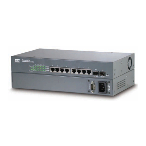
1.2 Product Panels The following figure illustrates the front panel and rear panel of the switch: Front panel Rear panel – Managed models with AC power Rear panel – Managed models with DC power Rear panel – Unmanaged models with AC power -10-... -
Page 11: Led Indicators
1.3 LED Indicators Function Power Power status Management status 1000M 1000Mbps link & activity status (Port 1 - Port 8) 10/100M 10Mbps or 100Mbps link & activity status (Port 1 - Port 8) PoE power output status (Port 1 - Port 8) SFP Fiber is selected on Port 7 SFP Fiber is selected on Port 8 1.4 Specifications... - Page 12 Configuration Auto/Forced, 1000Mbps, Full duplex Transmission rate 1000Mbps Network cables MMF 50/125 60/125, SMF 9/125 Eye safety IEC 825 compliant Console Port Interface RS-232, DTE type Connector 9-pin D-sub Switch Functions MAC Addresses Table 8K entries Forwarding & filtering Non-blocking, full wire speed Switching technology Store and forward Maximum packet length 1526 bytes (when Jumbo frame support disabled)
- Page 13 Software Management Functions Interfaces Web browser Management objects System configuration - IP settings, Name, Password Port configuration control and status VLAN function settings Port Link Aggregation function settings Link Aggregation LACP settings RSTP settings 802.1X port access control Port mirroring settings QoS function settings Storm protection control settings Port statistic, LACP status, RSTP status...
- Page 14 Storage Temperature C ~ +85 Relative Humidity 10% ~ 90% non-condensing Electrical Approvals Part 15 rule Class A EMC, CISPR22 Class A Safety LVD, IEC60950 -14-...
-
Page 15: Installation
2. Installation 2.1 Unpacking The product package contains: The switch unit One AC power cord (Models with AC power) One 19” rack mounting kit One product CD-ROM 2.2 Safety Cautions To reduce the risk of bodily injury, electrical shock, fire and damage to the product, observe the following precautions. -
Page 16: Mounting The Switch
2.3 Mounting the Switch Desktop Mounting The switch can be mounted on a desktop or shelf. Make sure that there is proper heat dissipation from and adequate ventilation around the device. Do not place heavy objects on the device. Rack Mounting Two 19-inch rack mounting brackets are supplied with the switch for 19-inch rack mounting. -
Page 17: Ac Power Supply
2.4 AC Power Supply If the purchased switch is with AC power input, one AC power cord which meets the specification of your country of origin was supplied in package. Before installing AC power cord to the switch, make sure the AC power is OFF and the AC power to the power cord is turned off. -
Page 18: Reset Button
2.6 Reset Button The reset button is used to perform a reset to the switch. It is not used in normal cases and can be used for diagnostic purpose. If any network hanging problem is suspected, it is useful to push the button to reset the switch without turning off the power. -
Page 19: Making Fiber Connection
function via software management to set forced mode and specify speed and duplex mode which match the configuration used by the connected device. 2.8 Making Fiber Connection The SFP slot must be installed with an SFP fiber transceiver for making fiber connection. Your switch may come with some SFP transceivers pre-installed when it is shipped. -
Page 20: Making Poe Connections
2.9 Making PoE Connections This section describes how to make a connection between a PSE port and a PoE PD device. In the models with PoE function option, all copper ports are equipped with PoE PSE function. The ports are enabled to deliver power together with network signal to a connected powered device via Cat.5 cable. -
Page 21: Led Indication
2.10 LED Indication Function State Interpretation Power Power status The power is supplied to the switch. The power is not supplied to the switch. Management status The switch is in initialization and diagnostics. BLINK The switch is initialized completely with diagnostic error. The switch is initialized completely and normal. -
Page 22: Console Commands
2.11.1 Console Commands Three command sets are provided as follows: System commands >System↵ System>Info ; display system information Name: ; System name of this switch unit S/W Version: x.xx ; Software version H/W Version: x.xx ; Hardware version MAC address: xx-xx-xx-xx-xx-xx ;... -
Page 23: Configuring Ip Address And Password For The Switch
2.12 Configuring IP Address and Password for the Switch The switch is shipped with the following factory default settings for software management: IP address of the switch: 192.168.0.2 / 255.255.255.0 Default The IP Address is an identification of the switch in a TCP/IP network. Each switch should be designated a new and unique IP address in the network. -
Page 24: Advanced Functions
3. Advanced Functions This chapter describes some advanced functions provided by the switch. 3.1 Abbreviation Ingress Port: Ingress port is the input port on which a packet is received. Egress Port: Egress port is the output port from which a packet is sent out. IEEE 802.1Q Packets: A packet which is embedded with a VLAN Tag field VLAN Tag: In IEEE 802.1Q packet format, 4-byte tag field is inserted in the original Ethernet frame between the Source Address and Type/Length fields. -
Page 25: Qos Function
3.2 QoS Function The switch provides a powerful Quality of Service (QoS) function to guide the packet forwarding in four priority classes. The versatile classification methods can meet most of the application needs. The following figure illustrates the QoS operation flow when a packet received on the ingress port until it is transmitted out from the egress port: -25-... -
Page 26: Packet Priority Classification
3.2.1 Packet Priority Classification Each received packet is examined and classified into one of four priority classes, Class 3, Class 2, Class 1 and Class 0 upon reception. The switch provides the following classification methods: 802.1p classification: use User Priority tag value in the received IEEE 802.1Q packet to map to one priority class DSCP classification: use DSCP value in the received IP packet to map to one priority class Port-based classification: used when 802.1p and DSCP are disabled or fail to be applied They all can be configured to be activated or not. -
Page 27: Vlan Function
3.3 VLAN Function The switch supports port-based VLAN, 802.1Q Tag VLAN and eight VLAN groups. 3.3.1 VLAN Operation The following figure illustrates the basic VLAN operation flow beginning from a packet received on an ingress port until it is transmitted from an egress port. The following sections describe the VLAN processes and Advanced VLAN mode settings provided by the switch. -
Page 28: Drop Untagged Per Port Setting
3.3.2.3 Drop Untagged Per Port Setting Enable - All untagged packets and priority-tagged packets are dropped. A priority-tagged packet is treated as an untagged packet in this switch. Only VLAN-tagged packets are admitted. Disable - Disable Untagged packet filtering 3.3.2.4 Drop Tagged Per Port Setting Enable - All VLAN-tagged packets are dropped. -
Page 29: Vlan Group Table Configuration
3.3.5 VLAN Group Table Configuration The switch provides a table of eight VLAN groups to support up to eight VLANs at the same time. Each VLAN group is associated to one unique VLAN. The table is referred for VLAN classification. A VLAN group contains the following configuration settings: VID: 12-bit VLAN Identifier index to the VLAN to which the group is associated Member Ports: the admitted egress ports for packets belonging to this VLAN... -
Page 30: Egress Tagging Rules
3.3.8 Egress Tagging Rules Egress Tagging rules are used to make change to the packet before it is stored into egress queue of an egress port. Three egress settings are provided for each port and are described as follows: 3.3.8.1 Egress Settings Insert Tag (per port setting) Enable - Insert the Tag data of the associated Packet Tag information into the packet Disable - No tagging is performed. -
Page 31: 802.1X Authentication
3.4 802.1X Authentication For some IEEE 802 LAN environments, it is desirable to restrict access to the services offered by the LAN to those users and devices that are permitted to make use of those services. IEEE 802.1X Port-based network access control function provide a means of authenticating and authorizing devices attached to a LAN port that has point-to-point connection characteristics, and of preventing access to that port in cases in which the authentication and authorization process fails. - Page 32 are passed from the port on the supplicant into the switching engine. If the PC attached to the switch did not understand the EAP PDU that it was receiving from the switch, it would not be able to send an ID and the port would remain unauthorized.
-
Page 33: Web Management
4. Web Management The switch features an http server which can serve the management requests coming from any web browser software over TCP/IP network. Web Browser Compatible web browser software with JAVA script support Microsoft Internet Explorer 4.0 or later Netscape Communicator 4.x or later Set IP Address for the System Unit Before the switch can be managed from a web browser software, make sure a unique IP address is configured... -
Page 34: Main Management Menu
The switch will accept only one successful management connection at the same time. The other connection attempts will be prompted with a warning message as the right display above. A new connection will be accepted when the current user logout successfully or auto logout by the switch due to no access for time out of 3 minutes. - Page 35 Configuration System Switch information, system and IP related settings Ports Port link status, port operation mode configuration VLAN VLAN related configuration Aggregation Port link aggregation (port trunking) related configuration LACP LACP configuration for port link aggregation RSTP RSTP (Rapid spanning tree protocol) related configuration 802.1X 802.1X authentication related configuration Mirroring...
-
Page 36: System
4.4 System -36-... - Page 37 Configuration Description MAC Address The MAC address factory configured for the switch It can not be changed in any cases. S/W Version The firmware version currently running H/W Version The hardware version currently operating Active IP Address Currently used IP address for the switch management Active Subnet Mask Currently used subnet mask for IP address for the switch management Active Gateway...
-
Page 38: Management Vlan
4.4.1 Management VLAN Management VLAN settings allow administrator to access the switch and perform the switch management over a dedicated VLAN. The following rules are applied with the Management VLAN: 1. If the VLAN function is disabled, Management VLAN settings are ignored and no VLAN limitation is applied in accessing the switch web management interface. -
Page 39: Ports
4.5 Ports Configuration Function Enable Jumbo Frames Select to enable jumbo frame support Port The port number Link Speed and duplex status with green background - port is link on Down with red background - port is link down Mode Select port operating mode Disabled - disable the port operation Mode... -
Page 40: Sfp Ddm Status
v - set to enable PoE function [SFP DDM] Click to display DDM information and status of the SFP transceivers [Apply] Click to apply the configuration change Notes: 1. Combo Port #7 supports two media types, RJ-45 and 100Mbps fiber with SFP slot. Default setting “Auto Speed”... - Page 41 Information Function Port Port number which has SFP slot (Port 7 and Port 8 come with SFP.) Identifier The identifier information of the transceiver Connector The connector type used on the transceiver SONET Compliance SONET compliance information of the transceiver GbE Compliance Gigabit Ethernet compliance information of the transceiver Vendor Name...
-
Page 42: Vlans
4.6 VLANs VLAN Configuration Description VLAN Disable Select to disable VLAN function All ports are allowed to communicate with each others freely with no VLAN limitation. Port-based VLAN Mode Simple configuration for 2 port-based VLAN groups Port-based VLAN ISP Mode Simple configuration for 5 port-based VLAN groups Advance VLAN Mode Full VLAN configuration for port-based and Tag-based VLAN... -
Page 43: Port-Based Vlan Mode
4.6.1 Port-based VLAN Mode Configuration Description Group 1, 2 Port-based VLAN group number Member ports Select member ports for the group [Apply] Click to apply the configuration change [Refresh] Click to refresh current configuration [Back] Click to go back to upper menu Operation in this mode: 1. -
Page 44: Port-Based Vlan Isp Mode
4.6.2 Port-based VLAN ISP Mode Configuration Description Joint port Select a port as the joint port for all 7 port-based VLAN groups [Apply] Click to apply the configuration change [Refresh] Click to refresh current configuration [Back] Click to go back to upper menu Example: If Port 8 is selected as the joint port, the 7 port-based VLAN groups are configured as follows automatically: Group 1 - member [Port 1, Port 8]... -
Page 45: Advanced Vlan Mode
Mode Operation: 1. The joint port is the shared member port for all groups. 2. Two member ports are configured in each group. 3. The member ports in same group can communicate with other only. 4. No packet tag is examined. 5. - Page 46 Configuration Description Port Port number PVID Port VID, VID for Ingress Default Tag 1 ~ 4095 - decimal 12-bit VID value CFI for Ingress Default Tag 0, 1 - 1-bit CFI value User Priority User priority for Ingress Default Tag 0 ~ 7 - decimal 3-bit value [Apply] Click to apply the configuration change...
-
Page 47: Ingress Settings
4.6.3.2 Ingress Settings Configuration Description Port Port number Tag Aware Check tag data for every received packet Tag-aware - set to activate Tag-based mode Tag-ignore - set to use port-based mode and ignore any tag in packet Keep Tag Tag is removed from the received packet if exists Enable - set to activate tag removal for VLAN-tagged packets Disable - set to disable tag removal function Drop Untag... - Page 48 1. Priority-tagged packet (VID=0) is treated as untagged packet in the switch. 2. [Tag Aware] setting affects the index used for VLAN classification (VLAN table lookup). The following table lists the index used: Ingress [Tag Aware] setting Received packet type Tag-ignore Tag-aware Untagged...
-
Page 49: Egress Settings
4.6.3.3 Egress Settings Configuration Description Port Port number Insert Tag Activate tagging (Insert a tag to the packet) Enable - set to activate tagging Disable - set to disable tagging function Untagging Specific VID No tag insertion if packet tag information matches [Untagged VID] Enable - set to enable this function Disable - set to disable this function Untagged VID... -
Page 50: Vlan Groups
4.6.3.4 VLAN Groups Configuration Description Group Group number VID of the VLAN to which this group is associated 1 ~ 4095 - decimal 12-bit VID value Member Ports Select the admitted egress ports for the packets belong to the VLAN Port 1 ~ 8 - click to select Source Port Check Check whether the ingress port is the member port of the VLAN... -
Page 51: Important Notes For Vlan Configuration
4.6.4 Important Notes for VLAN Configuration Some considerations should be checked in configuring VLAN settings: 1. Switch VLAN Mode selection It is suggested to evaluate your VLAN application first and plan your VLAN configuration carefully before applying it. Any incorrect setting might cause network problem. 2. -
Page 52: Aggregation
4.7 Aggregation Configuration Description Group Trunk group number Port # Click to select the port as member port of the trunk group [Apply] Click to apply the configuration change [Refresh] Click to refresh current configuration [Back] Click to go back to upper menu Link aggregation function allows making connection between two switches using more than one physical links. -
Page 53: Lacp
4.8 LACP Configuration Description Port Port number Protocol Enabled Enable LACP support for the port Key Value An integer value assigned to the port that determines which ports are aggregated into an LACP link aggregate. Set same value to the ports in same LACP link aggregate. -
Page 54: Rstp
4.9 RSTP Configuration Description System Priority The lower the bridge priority is the higher priority it has. Usually, the bridge with the highest bridge priority is the root. Value: 0 ~ 61440 Hello Time Hello Time is used to determine the periodic time to send normal BPDU from designated ports among bridges. - Page 55 moved to Forwarding state of a port in bridge. Force Version Two options are offered for choosing STP algorithm. Compatible - STP (IEEE 802.1D) Normal - RSTP (IEEE 802.1w) Aggregations Enabled to support port trunking in STP. It means a link aggregate is treated as a physical port in RSTP/STP operation.
-
Page 56: 802.1X Configuration
4.10 802.1X Configuration Configuration Description Mode Disabled - disable 802.1X function Enabled - enable 802.1X function RADIUS IP IP address of the Radius server RADIUS UDP Port The UDP port for authentication requests to the specified Radius server RADIUS Secret The encryption key for use during authentication sessions with the Radius server. -
Page 57: 802.1X Re-Authentication Parameters
Port State Port 802.1X state 802.1X Disabled - the port is in 802.1X disabled state Link Down - the port is in link down state Authorized (green color) - the port is in 802.1X authorized state Unauthorized (red color) - the port is in 802.1X unauthorized state [Re-authenticate] Click to perform a manual authentication for the port [Force Reinitialize]... -
Page 58: Mirroring
4.11 Mirroring Configuration Description Mirror Port The designated port is forwarded all packets received on the mirrored source ports Mirror Source Select the ports which will be mirrored all received packets to the mirror port. [Apply] Click to apply the configuration change [Refresh] Click to refresh current configuration -58-... -
Page 59: Quality Of Service
4.12 Quality of Service QoS Configuration Description Port Port number 802.1p 802.1p priority classification Enable - set to enable this classification to the port for priority-tagged and VLAN-tagged packets Disable - 802.1p classification is not applied to the port DSCP DSCP classification Enable - set to enable DSCP classification to the port for IP packets Disable - DSCP classification is not applied to the port... -
Page 60: 802.1P Mapping
Note: 802.1p classification is superior over DSCP classification if both are enabled. That means if a received packet is classified successfully in 802.1p classification, the classified priority class is used directly for the packet and the result of DSCP classification is ignored. 4.12.1 802.1p Mapping Configuration Description... -
Page 61: Dscp Mapping
4.12.2 DSCP Mapping Configuration Description DSCP [0-63] Seven user-defined DSCP values which are configured with a priority class 0 ~ 63 - 6-bit DSCP value in decimal Priority The priority class configured for the user-defined DSCP value Class 3 ~ Class 0 All others The other DSCP values not in the seven user-defined values are assigned a default priority class... -
Page 62: Qos Service Policy
4.12.3 QoS Service Policy Configuration Description Port Port number Policy Service policy for egress priority among four egress class queues Strict priority - high class queue is served first always till it is empty Weighted ratio priority Class 3:2:1:0 = 4:3:2:1 - weighted ratio 4:3:2:1 Weighted ratio priority Class 3:2:1:0 = 5:3:1:1 - weighted ratio 5:3:1:1 Weighted ratio priority Class 3:2:1:0 = 1:1:1:1 - weighted ratio 1:1:1:1 [Apply]... -
Page 63: Storm Control
4.13 Storm Control Configuration Description Broadcast Rate The rate limit of the broadcast packets transmitted on a port. Broadcast Rate The rate limit of the Multicast packets transmitted on a port. Flooded Unicast Rate The rate limit of the flooded unicast packets transmitted on a port. The flooded unicast packets are those unicast packets whose destination address is not learned in the MAC address table. -
Page 64: Statistics Overview
4.14 Statistics Overview Statistics Description Port Port number Tx Bytes Total of bytes transmitted on the port Tx Frames Total of packet frames transmitted on the port Rx Bytes Total of bytes received on the port Rx Frames Total of packet frames received on the port Tx Errors Total of error packet frames transmitted on the port Rx Errors... -
Page 65: Detailed Statistics
4.15 Detailed Statistics Button Description [Port #] Click to display the detailed statistics of Port #. [Clear] Click to reset all statistic counters [Refresh] Click to refresh the displayed statistic counters -65-... -
Page 66: Lacp Status
4.16 LACP Status Status Description Port The port number Normal Display the ports not LACP enabled. Group # The LACP group Status The LACP port status presented with color and a number <Down> - the port is link down <Blocked & #> - the port is blocked by RSTP and the # is the port number of LACP link partner <Learning>... - Page 67 Status Description Port The port number Protocol Active yes - the port is link up and in LACP operation no - the port is link down or not in LACP operation Partner Port Number The port number of the remote link partner Operation Port Key The operation key generated by the system -67-...
-
Page 68: Rstp Status
4.17 RSTP Status The following example shows three RSTP topologies operate in three VLANs configured in a switch. RSTP Status Description VLAN Id The VLAN which has STP enabled ports Bridge Id STP bridge ID [Priority:MAC address] detected in the associated VLAN Hello Time Hello Time is used to determine the periodic time to send normal BPDU from designated ports among bridges. - Page 69 RSTP Port Status Description Port/Group Port number VLAN Id The associated VLAN to which the RSTP port belongs (PVID) Path Cost The path cost of the RSTP port Edge Port Is the port an edge port? P2p Port Yes - The port operates in full duplex. Protocol The protocol version configured for the port - RSTP or STP Port State...
-
Page 70: Ping
4.18 Ping Ping Description Target IP Address The target IP address to which the ping command issues Count The number of ping commands generated Time Out (in secs) The time out for a reply (in seconds) [Apply] Start the ping command Status The command status Received replies... -
Page 71: Reboot System
4.19 Reboot System This menu is used to reboot the switch unit remotely with current configuration. Starting this menu will make your current http connection lost. You must rebuild the connection to perform any management operation to the unit. 4.20 Restore Default This menu is used to restore all settings of the switch unit with factory default values. -
Page 72: Logout
4.22 Logout This menu is used to perform a logout from the switch management. If current user does not perform any management operation over 3 minutes, the switch will execute an auto logout and abort the current connection. -72-... -
Page 73: Snmp Support
5. SNMP Support SNMP version support Snmp v1, v2c management Managed Objects MIB-II system OBJECT IDENTIFIER ::= { mib-2 1 } interfaces OBJECT IDENTIFIER ::= { mib-2 2 } OBJECT IDENTIFIER ::= { mib-2 4 } snmp OBJECT IDENTIFIER ::= { mib-2 11 } dot1dBridge OBJECT IDENTIFIER ::= { mib-2 17 } ifMIB... -
Page 74: Appendix. Factory Default Settings
Appendix. Factory Default Settings System Configuration DHCP Enabled Not select (disabled) Fallback IP Address 192.168.0.2 Fallback IP Subnet mask 255.255.255.0 Fallback Gateway IP 192.168.0.1 Management VLAN - VID Management VLAN - CFI Management VLAN - User priority WDT Enable Not select (disabled) Name Null Password... - Page 75 Joint Port Port 8 Advanced VLAN Mode Settings Ingress Default Tag - PVID 1 for all ports Ingress Default Tag - CFI 0 for all ports Ingress Default Tag - User Priority 0 for all ports Ingress Setting - Tag Aware Tag-ignore for all ports Ingress Setting - Keep Tag Enable for all ports...
- Page 76 VLAN Group 7 - Member Ports None VLAN Group 7 - Source Port Check Disable VLAN Group 8 - VID VLAN Group 8 - Member Ports None VLAN Group 8 - Source Port Check Disable Aggregation/Trunking Configuration Group 1 -4 Member Ports None LACP Port Configuration Protocol Enabled...
- Page 77 Admin State Force Authorized for all ports Reauthentication Enabled Reauthentication Period 3600 EAP Timeout Port 1~Port 8 - tag 1 Class 0 Port 1~Port 8 - tag 2 Class 1 Port 1~Port 8 - tag 3 Class 1 Port 1~Port 8 - tag 4 Class 2 Port 1~Port 8 - tag 5 Class 2...
- Page 78 DSCP 1 / Priority 0, Class 0 DSCP 2 / Priority 0, Class 0 DSCP 3 / Priority 0, Class 0 DSCP 4 / Priority 0, Class 0 DSCP 5 / Priority 0, Class 0 DSCP 6 / Priority 0, Class 0 DSCP 7 / Priority 0, Class 0 All others DSCP...
Need help?
Do you have a question about the KGS-0820 and is the answer not in the manual?
Questions and answers