
Related Manuals for KTI Networks KGS-0865


Summary of Contents for KTI Networks KGS-0865
- Page 1 KGS-0865 Industrial Managed 8-Port Gigabit Ethernet Switch Installation Guide DOC.231211A...
- Page 2 KTI Networks Inc. KTI Networks Inc. reserves the right to revise this documentation and to make changes in content from time to time without obligation on the part of KTI Networks Inc. to provide notification of such revision or change.
- Page 3 The information contained in this document is subject to change without prior notice. Copyright (C) All Rights Reserved. TRADEMARKS Ethernet is a registered trademark of Xerox Corp. FCC NOTICE This device complies with Part 15 of the FCC Rules. Operation is subject to the following two conditions: (1) This device may not cause harmful interference, and (2) This device must accept any interference received, including the interference that may cause undesired operation.
-
Page 4: Table Of Contents
Table of Contents 1. Introduction ..........................6 1.1 Features ......................7 1.2 Product Panels ....................8 1.3 LED Indicators ....................8 1.4 Specifications ....................9 2. Installation ..........................11 2.1 Unpacking ...................... 11 2.2 Safety Cautions ....................11 2.3 Mounting the Switch to a Din-Rail ..............12 2.4 Mounting the Switch on a Panel .............. - Page 5 4.5.5 Mirroring ...................... 37 4.5.6 LLDP ......................38 4.5.7 Quality of Service ..................40 4.5.7.1 802.1p Configuration ................. 41 4.5.7.2 DSCP Configuration .................. 42 4.6 Monitoring....................... 43 4.6.1 Statistics Overview ..................43 4.6.2 IGMP Status ....................44 4.6.3 LLDP Statistics .................... 45 4.6.4 LLDP Table....................
-
Page 6: Introduction
1. Introduction The switch provides eight 10/100/1000Mbps copper ports for connections to Ethernet, Fast Ethernet or Gigabit Ethernet devices. With the featured auto-negotiation function, the switch can detect and configure the connection speed and duplex automatically. The switch also provides auto-MDI/MDI-X function, which can detect the connected cable and switch the transmission wire pair and receiving pair automatically. -
Page 7: Features
For industrial environment, the device is designed with the following enhanced features exceeding that of commercial Ethernet switches: High and wide operating Temperature range Screw panel and DIN rail mounting support for industrial enclosure Industrial-rated Emission and Immunity performance 1.1 Features ... -
Page 8: Product Panels
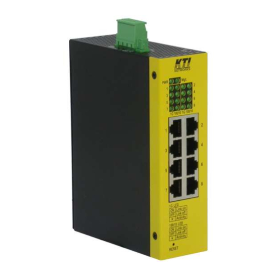
1.2 Product Panels The following figure illustrates the panels of the switch: 1.3 LED Indicators Function Power status Mgt. Management status Port 1 – Port 8 1 - 8 1Gbps link and activity status (Port 1 - Port 8) 100/10 100Mbps or 10Mbps link and activity status (Port 1 - Port 8) -
Page 9: Specifications
1.4 Specifications 10/100/1000 Twisted-pair Copper Port (UTP, RJ-45) Compliance IEEE 802.3 10Base-T, IEEE 802.3u 100Base-TX, IEEE 802.3u 1000Base-T Connectors Shielded RJ-45 jacks Pin assignments Auto MDI/MDI-X detection Configuration Auto-negotiation, manual settings or software control Transmission rate 10Mbps, 100Mbps, 1000Mbps Duplex support Full/Half duplex Network cable Cat.5 UTP or better... - Page 10 Mounting Din-rail mounting Panel mounting (with optional bracket) Environmental Operating Temperature Typical -30 C ~ +70 Storage Temperature C ~ +85 Relative Humidity 5% ~ 90% non-condensing Approvals Part 15 rule Class A EMC Class A VCCI Class A EN 61000-6-4 EN 61000-3-2 IEC 61000-3-3 IEC 61000-6-2...
-
Page 11: Installation
2. Installation 2.1 Unpacking The product package contains: The switch unit for Din-rail mounting One product CD-ROM 2.2 Safety Cautions To reduce the risk of bodily injury, electrical shock, fire and damage to the product, observe the following precautions. -
Page 12: Mounting The Switch To A Din-Rail
2.3 Mounting the Switch to a Din-Rail In the product package, a DIN-rail bracket is provided or has been installed for mounting the switch in a industrial DIN-rail enclosure. The steps to mount the switch onto a DIN rail are: 1. - Page 13 3. Clamp the unit to the DIN rail and make sure it is mounted securely. The final dimension is: -13-...
-
Page 14: Mounting The Switch On A Panel
2.4 Mounting the Switch on a Panel The switches may be provided optionally with a panel mounting bracket. The bracket supports mounting the switch on a plane surface securely. The mounting steps are: 1. Install the mounting bracket on the switch unit. 2. - Page 15 3. Screw the switch unit on a panel and the locations for screws are shown below: -15-...
-
Page 16: Applying Power
2.5 Applying Power Power pins of the terminal block connector Positive ( ) input terminal Negative ( ) input terminal DC+/- Input specifications Working voltage range: +8V ~ +57VDC WARNING: The -48VDC power supply is not supported. Terminal Plug &... -
Page 17: Alarm Relay Output
2.6 Alarm Relay Output Alarm relay output is provided for reporting failure events to a remote alarm relay monitoring system. The replay output is provided with two contacts on the terminal block connector next DC power interface. Alarm Relay output pins and logic: Alarm relay output, NO (Normal Open) contacts Open: normal, Shorted: Alarm The relay output can connect relay monitoring system. -
Page 18: Reset Button
2.7 Reset Button The reset button is used to perform a reset to the switch. It is not used in normal cases and can be used for diagnostic purpose. If any network hanging problem is suspected, it is useful to push the button to reset the switch without turning off the power. -
Page 19: Making Lan Connections
3. Making LAN Connections 3.1 10/100/1000 Copper Ports The 10/100/1000 RJ-45 copper ports support the following connection types and distances: Network Cables 10BASE-T: 2-pair UTP Cat. 3, 4, 5 , EIA/TIA-568B 100-ohm 100BASE-TX: 2-pair UTP Cat. 5, EIA/TIA-568B 100-ohm 1000BASE-T: 4-pair UTP Cat. -
Page 20: Led Indication
3.2 LED Indication Function State Interpretation Power status The power is supplied to the switch. The power is not supplied to the switch. Mgt. Management status During initialization (about 15 minutes) Error report after initialization Initialization and diagnostics finished with no error Relay alarm event occurred during normal operation and LED OFF after the event is recovered. - Page 21 3.3 Configuring IP Address and Password for the Device The device unit was shipped with the following factory default settings for software management: Default IP address of the device: 192.168.0.2 / 255.255.255.0 The IP Address is an identification of the device unit in a TCP/IP network. Each unit should be designated a new and unique IP address in the network.
-
Page 22: Web Management
4. Web Management 4.1 Abbreviation TP Port: The twisted-pair copper port of the media converter device. Ingress Port: Ingress port is the input port on which a packet is received. Egress Port: Egress port is the output port from which a packet is sent out. IEEE 802.1Q Packets: A packet which is embedded with a VLAN Tag field VLAN Tag: In IEEE 802.1Q packet format, 4-byte tag field is inserted in the original Ethernet frame between the Source Address and Type/Length fields. -
Page 23: Start Browser Software And Making Connection
C-tag: Tag with TPID 0x8100 S-tag: Tag with TPID 0x88A8 Priority S-tagged frame: Priority tagged frame with S-tag (TPID=0x88A8, VID=0) Priority C-tagged frame: Priority tagged frame with C-tag (TPID=0x8100, VID=0) > S-tagged frame: Tagged frame with S-tag (TPID=0x88A8, VID > C-tagged frame: Tagged frame with C-tag (TPID=0x8100, VID PVID (Port VID): PVID is the default VID of VLAN unaware ingress port. -
Page 24: Main Management Menu
attempts will be prompted with a warning message. A new connection will be accepted when the current user logout successfully or auto logout by the device due to no access for time out of 5 minutes. System Configuration is displayed after a successful login. 4.4 Main Management Menu -24-... - Page 25 The following information describes the basic functions of the main menu. Configuration System Device information, system and IP related settings Ports Port link status, operation mode configuration and other per port settings VLANs 802.1Q VLAN settings IGMP Snooping Configuration for IGMP snooping function Mirroring Mirroring function settings LLDP...
-
Page 26: Configuration
4.5 Configuration 4.5.1 System Configuration Description MAC Address The MAC address factory configured for the switch. It can not be changed in any cases. S/W Version Firmware version currently running H/W Version Hardware version currently operating Active IP Address Current IP address for the switch management -26-... - Page 27 Active Subnet Mask Current subnet mask for IP address for the switch management Active Gateway Current gateway IP address for the switch management DHCP Server Current IP address of the DHCP server Lease Time Left The time left for the lease IP address currently used DHCP Enabled Use DHCP to get dynamic IP address configuration for the switch Fallback IP Address...
-
Page 28: Management Vlan
4.5.1.1 Management VLAN Management VLAN settings allow administrator to access the device and perform the management over a dedicated VLAN. T he following rules are applied with the Management VLAN: 4 5 4 B I f [Management VLAN] setting is VID=0, no limitation is applied in accessing the web management 4 5 5 B 4 5 6 B interface, but password authentication. -
Page 29: Ports
4.5.2 Ports EEE is a power saving option that reduces the power usage when there is low or no traffic utilization. EEE works by powering down circuits when there is no traffic. When a port gets data to be transmitted all circuits are powered up. - Page 30 Enable 802.3az EEE mode v - set to enable the function ___________________________________________________________________________________________________________________________________________________ Port Configuration Function ___________________________________________________________________________________________________________________________________________________ Port TP - Twisted-Pair copper port (also specified Port #1 in other pages) FX - Fiber port (also specified Port #2 in other pages) Link Port link status Speed and duplex status with green background - port is link on...
-
Page 31: Vlans
4.5.3 VLANs 4.5.3.1 Add a VLAN __________________________________________________________________________ _________________________________________________________________________ Configuration Function ___________________________________________________________________________________________________________________________________________________ VLAN ID Specify the VLAN to be added. ___________________________________________________________________________________________________________________________________________________ [Add] Click to add one new VLAN. ___________________________________________________________________________________________________________________________________________________ -31-... - Page 32 ___________________________________________________________________________________________________________________________________________________ Configuration Function ___________________________________________________________________________________________________________________________________________________ Member Port Check to select the port as a member of the VLAN List current configured VLANs – VID and member ports VLAN Member List ___________________________________________________________________________________________________________________________________________________ [Apply] Click to apply the configuration change [Refresh] Click to refresh current configuration [Back] Click to go to previous page ___________________________________________________________________________________________________________________________________________________...
-
Page 33: Modify Vlan Configuration
4.5.3.2 Modify VLAN Configuration ___________________________________________________________________________________________________________________________________________________ Configuration Function ___________________________________________________________________________________________________________________________________________________ VLAN group Select the VLAN to be modified for the member ports or deleted. ___________________________________________________________________________________________________________________________________________________ [Modify] Click to modify the members of the selected VLAN. [Delete] Click to delete the selected VLAN. [Refresh] Click to refresh current configuration ___________________________________________________________________________________________________________________________________________________... -
Page 34: Vlan Port Configuration
4.5.3.3 VLAN Port Configuration ___________________________________________________________________________________________________________________________________________________ Button Function ___________________________________________________________________________________________________________________________________________________ [Port Config] Click to set port configuration ___________________________________________________________________________________________________________________________________________________ ___________________________________________________________________________________________________________________________________________________ Configuration Function ___________________________________________________________________________________________________________________________________________________ Port The switch port Port Type Specify VLAN mode for the port unaware – Unaware to VLAN tagged packets c-port – VLAN aware for received C-tagged & S-tagged packets. Each received packet is classified to a classified tag and VLAN ID (VID) depending -34-... - Page 35 on the Ingress port’s port type. The outer tag is referred if exists. The rule is: Received packet type Classified Tag Unaware C-port Untagged Default Tag Default Tag Priority tagged (VID=0) Default Tag Default Tag C-tagged & S-tagged Default Tag Packet’s Tag Other tagged Default Tag...
-
Page 36: Igmp Snooping
All – all types are accepted. Tagged – C-tagged & S-tagged packets are accepted. Untagged – all are accepted except c-tagged and S-tagged packets. PVID The default classified VID for the port Egress Tag Insert Rule Classified Tag insertion rule in egress operation No_PVID –... -
Page 37: Mirroring
Unregistered IPMC Flooding enabled Check to enable flooding un-registered IPMC packets. VLAN ID List of current existing VLANs IGMP Snooping Enabled Check to enable IGMP snooping on the associated VLAN. IGMP Querying Enabled Check to enable IGMP querying on the associated VLAN. _________________________________________________________________________________________________ __________________________________________________ [Apply] Click to apply the configuration change... -
Page 38: Lldp
4.5.6 LLDP Transmitted TLVs Description When checked the “port description” is included in LLDP information transmitted. Port Description When checked the “system name” is included in LLDP information transmitted. System Name When checked the “system description” is included in LLDP information transmitted. System Description When checked the “system capability”... - Page 39 Parameters Description Tx Interval The switch is periodically transmitting LLDP frames to its neighbors for having the network discovery information up-to-date. The interval between each LLDP frame is determined by the Tx Interval value. Valid values: 5 – 32768 seconds Tx Hold Each LLDP frame contains information about how long the information in the LLDP frame shall be considered valid.
-
Page 40: Quality Of Service
4.5.7 Quality of Service The device includes a number of QoS features related to providing low-latency guaranteed services to critical network traffic such as voice and video in contrast to best-effort traffic such as web traffic and file transfers. All incoming frames are classified to a QoS class, which is used in the queue system when assigning resources, in the arbitration from ingress to egress queues and in the egress scheduler when selecting the next frame for transmission. -
Page 41: 802.1P Configuration
4.5.7.1 802.1p Configuration Configuration Description QoS Mode 802.1p, DSCP Priority Traffic Preset the 802.1p mapping table Custom – set priority for each PCP value All Low Priority – set whole table to low priority All Normal Priority - set whole table to normal priority All Medium Priority - set whole table to medium priority All High Priority - set whole table to high priority 802.1p Value... -
Page 42: Dscp Configuration
4.5.7.2 DSCP Configuration Configuration Description QoS Mode 802.1p, DSCP Priority Traffic Preset the DSCP mapping table Custom – set priority for each PCP value All Low Priority – set whole table to low priority All Normal Priority - set whole table to normal priority All Medium Priority - set whole table to medium priority All High Priority - set whole table to high priority DSCP Values(0..63) -
Page 43: Monitoring
The rest values are mapped to single one priority. ___________________________________________________________________________________________________________________________________________________ [Apply] Click to apply the configuration change [Cancel] Click to cancel the configuration change ___________________________________________________________________________________________________________________________________________________ Note: 1. DSCP classification is applied to IPv4 and IPv6 frames. 2. Non-IP frames are given 0 for DSCP. 4.6 Monitoring 4.6.1 Statistics Overview Statistics... -
Page 44: Igmp Status
[Refresh] Click to refresh all statistic counters 4.6.2 IGMP Status _ __________________________________________________________________________________________________________________________________________________ 7 5 2 B U S tatus Description 1 1 5 4 B _ __________________________________________________________________________________________________________________________________________________ 7 5 3 B U V LAN ID The VLAN ID of the entry. 1 1 5 5 B Show the Querier status is “Active”... -
Page 45: Lldp Statistics
4.6.3 LLDP Statistics Counters Description Port The port on which LLDP frames are received or transmitted. (Port #1: TP port, Port #2: FX port) Tx Frames The number of LLDP frames transmitted on the port. Rx Frames The number of LLDP frames received on the port. Rx Error Frames The number of received LLDP frames containing error. -
Page 46: Lldp Table
4.6.4 LLDP Table Status Description Local Port The port on which the LLDP frame was received. (Port #1: TP port, Port #2: FX port) Chassis Id The Chassis Id is the identification of the neighbor's LLDP frames. Remote Port ID Port ID of the neighbor port System Name System Name advertised by the neighbor unit... - Page 47 9. Reserved When a capability is enabled, the capability is followed by (+). If the capability is disabled, the capability is followed by (-). Management Address Management Address is the neighbor unit's address that is used for higher layer entities to assist discovery by the network management. This could for instance hold the neighbor's IP address.
-
Page 48: Ping
4.6.5 Ping Ping Description Target IP Address The target IP address to which the ping command issues Count Number of ping commands generated Time Out (in secs) Time out for a reply (in seconds) [Apply] Start the ping command Results Description Target IP Address The target IP address to which the ping command issues... -
Page 49: Maintenance
4.7 Maintenance 4.7.1 Reboot System This menu is used to reboot the device unit remotely with current configuration. Starting this menu will make your current http connection lost. You must rebuild the connection to perform any management operation to the unit. 4.7.2 Restore Default This menu is used to restore all settings of the device unit with factory default values except current IP configuration and Management VLAN configuration. -
Page 50: Configuration File Transfer
[Upload] Click to start upload 4.7.4 Configuration File Transfer This [download] command can be used to backup current device configuration and download it to the connected management PC. The default filename is “switch.cfg”. Configuration Description Filename Path and filename of a backup configuration file to be uploaded [Browse] Click to browse your computer file system for the configuration file [Upload]... -
Page 51: Snmp Support
5. SNMP Support S NMP version support Snmp v1, v2c management 1 2 3 0 B M anaged Objects MIB-II 1 2 3 1 B system OBJECT IDENTIFIER ::= { mib-2 1 } interfaces OBJECT IDENTIFIER ::= { mib-2 2 } OBJECT IDENTIFIER ::= { mib-2 4 } snmp OBJECT IDENTIFIER ::= { mib-2 11 }... -
Page 52: Appendix A. Factory Default Settings
Appendix A. Factory Default Settings System Configuration DHCP Enabled Disable Fallback IP Address 192.168.0.2 Fallback Subnet Mask 255.255.255.0 Fallback Gateway 0.0.0.0 Management VLAN Name Null Password Inactivity Timeout (secs) SNMP enabled Disable SNMP Trap destination 0.0.0.0 SNMP Read Community public SNMP Write Community private SNMP Trap Community... - Page 53 Unregistered IPMC Flooding enabled VLAN1 IGMP Snooping Enabled yes VLAN1 IGMP Querying Enabled yes Mirror Source none Mirror Port TLV Port Description TLV System Name TLV System Description TLV System Capabilities TLV Management Address LLDP Tx Interval LLDP Tx Hold LLDP Tx Delay LLDP Reinit Delay LLDP State...
Need help?
Do you have a question about the KGS-0865 and is the answer not in the manual?
Questions and answers