
Related Manuals for KTI Networks KGS-2461-S


Summary of Contents for KTI Networks KGS-2461-S
- Page 1 KGS-2461-S KGS-2461-HP Industrial Managed 24-Port L2/L3 Gigabit Ethernet Switches with PoE+ features Installation Guide DOC.230626...
- Page 2 KTI Networks Inc. KTI Networks Inc. reserves the right to revise this documentation and to make changes in content from time to time without obligation on the part of KTI Networks Inc. to provide notification of such revision or change.
- Page 3 The information contained in this document is subject to change without prior notice. Copyright (C) All Rights Reserved. TRADEMARKS Ethernet is a registered trademark of Xerox Corp. FCC NOTICE This device complies with Part 15 of the FCC Rules. Operation is subject to the following two conditions: (1) This device may not cause harmful interference, and (2) This device must accept any interference received, including the interference that may cause undesired operation.
-
Page 4: Table Of Contents
2. Installation..............................14 2.1 Unpacking ..........................14 2.2 Safety Cautions........................14 2.3 Mounting the Switch......................15 2.4 Applying AC Power Supply (KGS-2461-S) ................16 2.5 Applying DC Power Supply (KGS-2461-HP)................ 17 2.6 Reset Button ........................18 2.7 Making UTP Connections ....................18 2.8 Making SFP Fiber Connection ..................... -
Page 5: Introduction
SSH, HTTPS, IEEE 802.1x & MAC-based authentication, and ACL control to make them suitable for industrial core applications. Model Definition Model No. Model Power Input Power connector PoE+ feature KGS-2461-S AC powered model AC 100 ~ 240V IEC320 Screw terminals KGS-2461-HP DC powered model DC +/-40~57V... -
Page 6: Features
1.1 Features Provide 24 10/100/1000Mbps RJ-45 and four dual speed SFP slots (4 combo ports) Provide optional 24 802.3at compliant PoE+ PSE ports All copper ports support auto-negotiation and auto-MDI/MDI-X detection The SFP slots support both 100BASE-X and 1000BASE-X SFP transceivers ... - Page 7 - Policers for ACL rules - Port egress bandwidth shaper - Queue egress bandwidth shaper - DiffServ (RFC2474) DSCP based classification and remarking - Tag based remarking - Port scheduler mode for egress queue Layer2 - Auto MAC address learning and ageing - Static MAC address filtering - 802.1Q VLAN - VLAN trunking...
- Page 8 - IP/MAC binding dynamic to static - TACACS+ Protocol for authenticating users that wish to manage the switch. - TACACS+ Accounting - Web & CLI Authentication - User Authorization Levels for CLI and Web management. - Web-based Authentication - Authorization (15 user levels) - ACLs for filtering/policing/port copy - Access Control Lists for filtering, policing or port copy - IP source guard - Access Control List for L2/L3 protocol filtering, ingress rate limit, port copy...
- Page 9 SFP DDM...
-
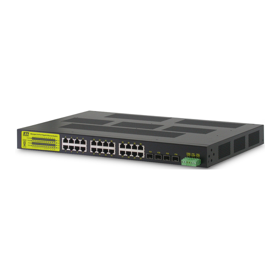
Page 10: Product Panels
1.2 Product Panels The following figure illustrates the front panel and rear panel of the switch: Model Front & Rear powered model powered model 1.3 LED Indicators Function POWER Power status Mngt Management status 1000M Port speed status, PoE status Link/Act. - Page 11 10/100/1000 Copper Ports (Port 1 ~ Port 24) Compliance IEEE 802.3 10Base-T, IEEE 802.3u 100Base-TX, IEEE 802.3u 1000Base-T Connectors Shielded RJ-45 jacks Pin assignments Auto MDI/MDI-X detection Configuration Auto-negotiation or software control Transmission rate 10Mbps, 100Mbps, 1000Mbps Duplex support Full/Half duplex Network cable Cat.5 UTP Power over Ethernet PSE Function (Model KGS-2461-HP only)
- Page 12 Interface RS-232, DTE type Connector 9-pin D-sub Switch Functions MAC Addresses Table 8K entries Forwarding & filtering Non-blocking, full wire speed Switching technology Store and forward Maximum packet length 10056 bytes (Jumbo frame support) Flow control IEEE 802.3x pause frame base for full duplex operation Back pressure for half duplex operation VLAN function Port-based VLAN and IEEE 802.1Q Tag-based VLAN...
- Page 13 Mounting Desktop mounting, 19” rack mounting Environmental Operating Temperature Typical -30 C ~ +60 Storage Temperature C ~ +85 Relative Humidity 10% ~ 90% non-condensing Certificates & Approvals Part 15 Subpart B, Class A VCCI:2005-04 Japan Emission std. , Class A CE mark European Conformity VCCI...
-
Page 14: Installation
2. Installation 2.1 Unpacking The product package contains: The switch unit One AC power cord (AC powered Model) One 19” rack mounting kit One product CD-ROM One RS-232 serial cable 2.2 Safety Cautions To reduce the risk of bodily injury, electrical shock, fire and damage to the product, observe the following precautions. -
Page 15: Mounting The Switch
2.3 Mounting the Switch Desktop Mounting The switch can be mounted on a desktop or shelf. Make sure that there is proper heat dissipation from and adequate ventilation around the device. Do not place heavy objects on the device. Rack Mounting Two 19-inch rack mounting brackets are supplied with the switch for 19-inch rack mounting. -
Page 16: Applying Ac Power Supply (Kgs-2461-S)
2.4 Applying AC Power Supply (KGS-2461-S) If the purchased switch is with AC power input, one AC power cord which meets the specification of your country of origin was supplied in package. Before installing AC power cord to the switch, make sure the AC power is OFF and the AC power to the power cord is turned off. -
Page 17: Applying Dc Power Supply (Kgs-2461-Hp)
2.5 Applying DC Power Supply (KGS-2461-HP) If the purchased switch is with DC power input, the power connector is shown below. It provides two power input interfaces, POWER A and POWER B. Each comes with one connector and one power switch. The design supports power redundancy to the device. -
Page 18: Reset Button
2.6 Reset Button The reset button is used to perform a reset to the switch. It is not used in normal cases and can be used for diagnostic purpose. If any network hanging problem is suspected, it is useful to push the button to reset the switch without turning off the power. -
Page 19: Making Sfp Fiber Connection
Link distance: Up to 100 meters Auto MDI/MDI-X Function This function allows the port to auto-detect the twisted-pair signals and adapts itself to form a valid MDI to MDI-X connection with the remote connected device automatically. No matter a straight through cable or crossover cable are connected, the ports can sense the receiving pair automatically and configure themselves to match the rule for MDI to MDI-X connection. - Page 20 To install an SFP fiber transceiver into SFP slot, the steps are: 1. Turn off the power to the switch. 2. Insert the SFP fiber transceiver into the SFP slot. Normally, a bail is provided for every SFP transceiver. Hold the bail and make insertion. 3.
-
Page 21: Making Poe Pse Connections (Kgs-2461-Hp)
2.9 Making PoE PSE Connections (KGS-2461-HP) This section describes how to make a connection between a PSE port and a PoE Powered D device (PD). All copper ports are equipped with PoE PSE function. The ports are enabled to deliver power together with network signal to a connected powered device via Cat.5 cable. -
Page 22: Led Indication
2.10 LED Indication Name Function State Color Interpretation POWER Power status Green Power is supplied to the device. POWER A status Amber DC POWER A input failed. DC POWER A input normal POWER B status Amber DC POWER B input failed. DC POWER B input normal Mngt Management... -
Page 23: Making Console Connection
2.11 Making Console Connection Console port is an isolated DB9 connector. It serves as an RS-232 DTE port. Pin Definitions Pin 2 Pin 3 Pin 5 Pin 1,4,6-9 NC Use simple RS232 null modem without handshaking to connect the console port to PC’s DB9 COM port as follows: Console Pins COM Port Pins... -
Page 24: Alarm Relay Output
2.12 Alarm Relay Output Three alarm relay outputs are equipped on the front panel. They provide relay output for reporting the device’s alarm events to the remote relay monitoring system. hree Relay Outputs There are three alarm ou tputs to indicate three different types of alarms. They are: 1. -
Page 25: Managing The Switch
3. Managing the Switch The switch provides the following methods to configure and monitor the switch as follows: Making out of band management via RS-232 console port Making in-band management via telnet interface over TCP/IP network Making in-band management via web interface over TCP/IP network ... -
Page 26: Configuring Local Authentication Via Console And Telnet Cli
# configure terminal (config)# interface vlan 1 (config-if-vlan)# ip address dhcp fallback 192.168.4.171 255.255.255.0 Remark: 1. With factory default, vlan 1 is the only one that includes all sw itched ports as port members. . vlan 1 uses dhcp for IP configuration. 3. -
Page 27: Configuring Ip Address & Password Via Web Interface
.4 Configuring IP Address & Password via Web Interface Start Web Browser Start your browser software and enter th e default IP address to which you want to connect. The IP address is used as URL for the browser software to search the device. URL: http:/192.168.0.2/ Login to the switch When browser software connects to the switch successfully, a Login screen is provided for you to login... - Page 28 IP Address Configuration Select [Configuration] -> [System] -> [IP] to configure IP address for VLAN 1 Configuration Description IPv4 DHCP DHCP client configuration Enable Enable the DHCP client by checking this box. If this option is enabled, the system will configure the IPv4 address and mask of the interface using the DHCP protocol. Fallback The number of seconds for trying to obtain a DHCP lease.
- Page 29 Configuration Description User Name The name identifying the user. This is also a link o Ad /Ed Use inte face. The privilege level of the user. The allowed ang is 1 Privilege Level . If t e privilege level value is 15, it can access all groups, i.e.
- Page 30 Add New User Configuration Description User Name A string identifying the user name that this entry shoul d belong to. The llowed st in length is 1 to 31. The valid user name allows letters, numbers and underscores. The password of the user. The allowed string length is 0 to 31. Any printable Password characters including space are accepted.
-
Page 31: Reference Manuals For Web, Console, Telnet Management
admin Configure password for user Select [Configuration] -> [Security] -> [Switch] -> [Users] to show all users. Click admin to edit configuration. admin Edit user page to configu re password for user: 3.5 Reference Manuals for Web, Console, Teln t M n a ag m e en The following o... -
Page 32: Configuration For Snmp Management
.6 Configuration for SNMP Management The switch supports SNMP v1, SNMP v2c, and SNMP v3 management. Make sure the related settings are well-configured for the switch before you start the SNMP management from a n SNMP manager. Using Telnet CLI The following are available commands in telnet SNMP command group to configure SNMP-related settings: (config)# snmp-server ? access... -
Page 33: Snmp Mibs
Basic system configuration for SNMP v1, SNMP v2c and SNMP v3 Basic system configuration for SNMP v1 trap, SNMP v2c trap and SNMP v3 trap Communities that permit to access to SNMPv3 agent User table for SNMPv3 Group table for SNMPv3 Viewer table for SNMPv3 Accesses group table for SNMP 3.7 SNMP MIBs... - Page 34 RADIUS accounting protoc RFC 5519 - Multicast Group Membership MIB module for MGMD management Discovery (MGMD) MIB (Obsoletes RFC 2933 and RFC 3019 MIBs) MIB module for managing devices that support IEEE IEEE 802.1 MSTP MIB 802.1multiple spanning tree groups. IEEE 802.1AB LLDP MIB MIBs defined in 802.1AB.
Need help?
Do you have a question about the KGS-2461-S and is the answer not in the manual?
Questions and answers