
Related Manuals for KTI Networks KGS-2422


Summary of Contents for KTI Networks KGS-2422
- Page 1 KGS-2422 Managed 24-Port Modular Gigabit Ethernet Switches with 100BASE-FX Support Installation Guide DOC.120322...
- Page 2 (C) 2012 KTI Networks Inc. All rights reserved. No part of this documentation may be reproduced in any form or by any means or used to make any directive work (such as translation or transformation) without permission from KTI Networks Inc.
- Page 3 The information contained in this document is subject to change without prior notice. Copyright (C) All Rights Reserved. TRADEMARKS Ethernet is a registered trademark of Xerox Corp. FCC NOTICE This device complies with Part 15 of the FCC Rules. Operation is subject to the following two conditions: (1) This device may not cause harmful interference, and (2) This device must accept any interference received, including the interference that may cause undesired operation.
-
Page 4: Table Of Contents
Table of Contents 1. Introduction..............................5 1.1 Features ..........................6 1.2 Product Panels........................8 1.3 Optional Modules ........................8 1.3.1 Optional Module Table ...................... 10 1.4 LED Indicators ........................10 1.5 Specifications ........................11 2. Installation..............................14 2.1 Unpacking ..........................14 2.2 Safety Cautions........................14 2.3 Installing Module ........................ -
Page 5: Introduction
ACL control to make them suitable for office core applications. The following figure illustrates the switch has 3 empty slots with no module installed. Model Definition Model No. Model Power Input Power connector KGS-2422-S AC powered model AC 100 ~ 240V IEC320 KGS-2422-D DC powered model DC +48V... -
Page 6: Features
1.1 Features Fully modular design with three 8-port module slots supporting Gigabit and Fast Ethernet A variety of optional modules is available for selection including Gigabit copper, Gigabit fiber, Gigabit mix of copper and fiber, and Fast Ethernet fiber The copper ports support 10/100/1000Mbps auto-negotiation and auto-MDI/MDI-X detection. The SFP port can support both 100Mbps fiber transceivers and Gigabit Ethernet SFP fiber transceivers Support connectivity for Fast Ethernet fiber, 100BASE-FX with SC/ST/BiDi/VF-45 transceivers Flexible installation with any combination of different modules in one rack... - Page 7 - Port QoS configuration - QoS Control List for policy rules - Port bandwidth control for ingress and egress - Storm Control for UC, MC and BC Layer2 - Auto MAC address learning and ageing - Static MAC address filtering - Port-based and 802.1Q Tag-based VLAN - Link Aggregation - LACP - Rapid Spanning tree - RSTP...
-
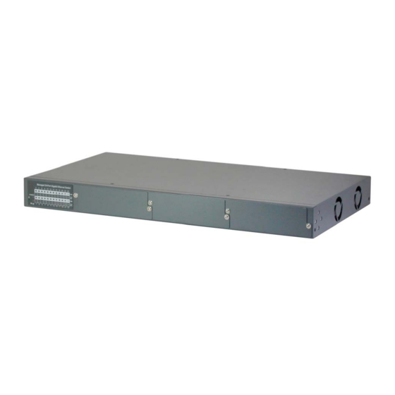
Page 8: Product Panels
1.2 Product Panels The following figure illustrates the front panel and rear panel of the switch: Model Front Panel Rear Panel (Power Input) AC powered model DC powered model 1.3 Optional Modules Module Part No. Image Specifications 8 10/100/1000 copper ports 8 RJ-45 jacks 8-port 100/1000 SFP module 8 dual-speed SFP slots... - Page 9 4 10/100/1000 copper ports (4 RJ-45) support 10/100/1000Mbps 4 dual-speed SFP slots support standard 100M or 1000M SFP optical fiber transceivers 8FX-xxx 8 fixed 100M fiber ports 8 duplex SC transceivers support 100Mbps Options: MMF 2km, SMF 20km 8FM-xxx 6 fixed 100M fiber ports with 6 duplex SC transceivers supporting 100Mbps 2 10/100/1000 copper ports (2...
-
Page 10: Optional Module Table
8FX-Wxxyy 8 fixed 100M fiber ports 8 BiDi SC transceivers support 100Mbps Options: Tx1310/Rx1550 SMF 20km Tx1550/Rx1310 SMF 20km 8FM-Wxxyy 6 fixed 100M fiber ports with 6 BiDi SC transceivers support 100Mbps 2 10/100/1000 copper ports (2 RJ-45) Fiber options: Tx1310/Rx1550 SMF 20km Tx1550/Rx1310 SMF 20km 1.3.1 Optional Module Table... -
Page 11: Specifications
1000M Port speed 1000Mbps status Link/Act. Port link and activity status (Port 1 – Port 24) 1.5 Specifications 10/100/1000 Copper Ports Compliance IEEE 802.3 10Base-T, IEEE 802.3u 100Base-TX, IEEE 802.3u 1000Base-T Connectors Shielded RJ-45 jacks Pin assignments Auto MDI/MDI-X detection Configuration Auto-negotiation or software control Transmission rate... - Page 12 Switch Functions MAC Addresses Table 8K entries Forwarding & filtering Non-blocking, full wire speed Switching technology Store and forward Maximum packet length 9600 bytes (Jumbo frame support) Flow control IEEE 802.3x pause frame base for full duplex operation Back pressure for half duplex operation VLAN function Port-based VLAN and IEEE 802.1Q Tag-based VLAN VLAN support...
- Page 13 Part 15 rule Class A EMC, CISPR22 Class A Safety LVD, IEC60950-1 -13-...
-
Page 14: Installation
2. Installation 2.1 Unpacking The product package contains: The switch unit One AC power cord (AC powered Model) One 19” rack mounting kit One product CD-ROM 2.2 Safety Cautions To reduce the risk of bodily injury, electrical shock, fire and damage to the product, observe the following precautions. -
Page 15: Installing Module
2.3 Installing Module The steps to install a module are: 1. Unscrew and open the cover of the module slot. 2. Insert the module into the slot until it is plugged on the slot connector properly. 3. Screw the module on the front panel of the base chassis securely. -15-... -
Page 16: Removing The Module
2.4 Removing the Module The steps to remove an installed module from a base chassis are: 1. Unscrew the module first. 2. Loosen two screw brackets and pull them out as shown below: 3. Use the brackets as handles to pull the module out from the module slot connector. -16-... -
Page 17: Mounting The Switch
4. Remove the module from the slot. 2.5 Mounting the Switch Desktop Mounting The switch can be mounted on a desktop or shelf. Make sure that there is proper heat dissipation from and adequate ventilation around the device. Do not place heavy objects on the device. Rack Mounting Two 19-inch rack mounting brackets are supplied with the switch for 19-inch rack mounting. -
Page 18: Applying Ac Power Supply
2. Mount the switch onto 19-inch rack with rack screws securely. 3. Turn the power to the switch on. 2.6 Applying AC Power Supply If the purchased switch is with AC power input, one AC power cord which meets the specification of your country of origin was supplied in package. -
Page 19: Applying Dc Power Supply
Frequency: 47 ~ 63 Hz Power Consumption: 40W max. 2.7 Applying DC Power Supply If the purchased switch is with DC power input, the power connector is shown below: DC power input specifications Receptacle: Screw-type terminal block Operating Voltages: +40 ~ +72VDC Power Consumption: 40W max. -
Page 20: Making Utp Connections
The button can also be used to restore the software configuration settings to factory default values. The operations are: Operation Function Press the button during system boot-up and release Restore factory default settings it after boot-up. The boot-up takes about 17 seconds and ends with LED diagnostics. -
Page 21: Making Sfp Fiber Connection
2.10 Making SFP Fiber Connection The dual-speed SFP slot must be installed with an SFP fiber transceiver for making fiber connection. Your switch may come with some SFP transceivers pre-installed when it was shipped. Since the SFP slot is dual-speed support, it may be installed with a 1000M SFP fiber transceiver or a 100M SFP fiber transceiver. -
Page 22: Making Fixed Duplex Fiber Connection
2.11 Making Fixed Duplex Fiber Connection The following figure illustrates an example of fixed duplex fiber port with duplex SC connectors. A module with fixed duplex ST connectors is also available in the listed optional modules. Identify TX and RX connector before making cable connection. Plug in the cables as shown below. Make sure RX-to-TX connection rule is followed between two ends of the connected cable. -
Page 23: Making Fixed Bi-Di (Bi-Directional) Fiber Connection
2.12 Making Fixed Bi-Di (Bi-Directional) Fiber Connection The following figure illustrates an example of fixed Bi-Di (Bi-directional) fiber port with one SC connector. A Bi-Di port supports single fiber connection. It uses different optical wavelengths for transmission and receiving individually as figure illustrated below: -23-... -
Page 24: Led Indication
2.13 LED Indication Function Color State Interpretation POWER Power status Green ON The power is supplied to the switch. The power is not supplied to the switch. Mngt Management status Green OFF The switch is in initialization and diagnostics. BLINK The switch is initialized completely with diagnostic error. The switch is initialized completely and normal. -
Page 25: Making Console Connection
100Mbps or 10Mbps is selected. Link/Act. Port link status Green ON Port link is established. (No traffic) BLINK Port link is up and there is traffic. Port link is down. 2.14 Making Console Connection Console port is a DB9 connector. It serves as an RS-232 DTE port. Pin Definitions Pin 2 Pin 3... -
Page 26: Managing The Switch
3. Managing the Switch The switch provides the following methods to configure and monitor the switch as follows: Making out of band management via RS-232 console port Making in-band management via telnet interface over TCP/IP network Making in-band management via web interface over TCP/IP network Making in-band SNMP management over TCP/IP network 3.1 IP Address &... - Page 27 Enter the following default values in the login page: Fixed User Name: admin Default password: No password is required. Click to login into the switch. The following page is displayed after a successful login: Select [Configuration] -> [Security] -> [Switch] -> [Password] to configure a new password -27-...
- Page 28 Password configuration web page Configuration Description Old Password Enter the current system password. If this is incorrect, the new password will not be set. New Password New system password to be used The allowed string length is 0 to 31, and the allowed content is the ASCII characters from 32 to 126.
-
Page 29: Configuring Ip Address & Password Via Console And Telnet
IP Address Provide the IP address of this switch unit. IP Mask Provide the IP mask of this switch unit. IP Router Provide the IP address of the default router for this switch unit. VLAN ID Provide the managed VLAN ID. The allowed range is 1 through 4095. SNTP Server Provide the IP address of the SNTP Server. -
Page 30: Configuration For Snmp Management
Operation manual - telnet & console management xxxxxx.doc Operation manual - web management xxxxx.doc The manuals describe the detailed commands and information. 3.5 Configuration for SNMP Management The switch supports SNMP v1, SNMP v2c, and SNMP v3 management. Make sure the related settings are well-configured for the switch before you start the SNMP management from an SNMP manager. -
Page 31: Snmp Mibs
>SNMP User Add <engineid> <user_name> [MD5|SHA] [<auth_password>] [DES] [<priv_password>] >SNMP User Delete <index> >SNMP User Changekey <engineid> <user_name> <auth_password> [<priv_password>] >SNMP User Lookup [<index>] >SNMP Group Add <security_model> <security_name> <group_name> >SNMP Group Delete <index> >SNMP Group Lookup [<index>] >SNMP View Add <view_name> [included|excluded] <oid_subtree> >SNMP View Delete <index>... - Page 32 - RFC 3635 Ethernet-like MIB - RFC 4188 Bridge MIB - RFC 3636 802.3 Medium Attachment Units (MAUs) MIB - RFC 2863 Interface Group MIB using SMI v2 - RFC 4133 Entity MIB v3 - RFC 2933 IGMP MIB - IEEE 802.3AB LLDP MIB One product MIB file is also available in the product CD for SNMP manager software.
Need help?
Do you have a question about the KGS-2422 and is the answer not in the manual?
Questions and answers