
Subscribe to Our Youtube Channel
Related Manuals for KTI Networks KGS-510F-C


Summary of Contents for KTI Networks KGS-510F-C
- Page 1 KGS-510F Ver.C Web Smart 6-Port Gigabit Ethernet Switch with Fiber Connectivity KGS-510F-C Software v1.07 or later Installation Guide DOC.120130...
- Page 2 KTI Networks Inc. KTI Networks Inc. reserves the right to revise this documentation and to make changes in content from time to time without obligation on the part of KTI Networks Inc. to provide notification of such revision or change.
- Page 3 The information contained in this document is subject to change without prior notice. Copyright (C). All Rights Reserved. TRADEMARKS Ethernet is a registered trademark of Xerox Corp. WARNING: This equipment has been tested and found to comply with the limits for a Class A digital device, pursuant to Part 15 of the FCC Rules.
-
Page 4: Table Of Contents
Table of Contents 1. Introduction ....................6 1.1 Features ........................7 1.2 Product Panels ......................7 1.3 LED Indicators ......................8 1.4 Specifications ......................8 2. Installation ....................10 2.1 Unpacking ....................... 10 2.2 Safety Cautions ...................... 10 2.3 Mounting the Switch ....................10 2.4 Applying Power ...................... - Page 5 4.1 Start Browser Software and Making Connection ............. 23 4.2 Login to the Switch Unit ................... 23 4.3 Main Management Menu ..................24 4.4 System ........................26 4.4.1 Management VLAN ....................28 4.5 Ports ........................29 4.6 VLANs ........................31 4.6.1 Port-based VLAN Mode ..................
-
Page 6: Introduction
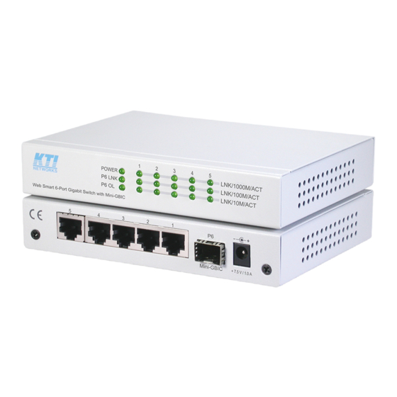
1. Introduction The KGS-510F-C is a managed 6-port Gigabit Ethernet switch which is featured with five copper ports, one mini-GBIC (SFP) port and the following advantages in a small footprint box: Plug and Play The switch is shipped with factory default configuration which behaves like an unmanaged Gigabit switch for workgroup. -
Page 7: Features
1.1 Features Provides 5 10/100/1000Mbps Gigabit Ethernet ports and 1 SFP port Provides in-band web-based management interface All copper ports support auto-negotiation and auto-MDI/MDI-X detection Provides full wire speed forwarding Supports 802.3x flow control for full-duplex and backpressure for half-duplex Provides port status, statistic monitoring and control function Supports port-based and 802.1Q Tag-based VLAN Provides QoS function... -
Page 8: Led Indicators
1.3 LED Indicators Function POWER Power status LNK/1000M/ACT Network port 1000M link status (Port 1 - Port 5) LNK/100M/ACT Network port 100M link status (Port 1 - Port 5) LNK/10M/ACT Network port 10M link status (Port 1 - Port 5) P6 LNK Port 6 1000M link status P6 OL... - Page 9 Port control Port configuration control via software management Storm control Broadcast, Multicast storm protection control via software management Aggregation Link aggregation (port trunking) Port Mirroring Mirror received frames to a sniffer port Software Management Functions Interfaces Web browser Management objects System configuration - IP settings, Name, Password Port configuration control and status, VLAN function settings Port Link Aggregation function settings...
-
Page 10: Installation
2. Installation 2.1 Unpacking The product package contains: • The switch unit • One product CD-ROM 2.2 Safety Cautions To reduce the risk of bodily injury, electrical shock, fire, and damage to the product, observe the follow- ing precautions. • Do not service any product except as explained in your system documentation. -
Page 11: Applying Power
2.4 Applying Power Before you begin the installation, check the AC voltage of your area. The AC power adapter which is used to supply the DC power for the unit should have the AC voltage matching the commercial power voltage in your area. -
Page 12: Making Utp Connections
2.6 Making UTP Connections The 10/100/1000 RJ-45 copper ports supports the following connection types and distances: Network Cables 10BASE-T: 2-pair UTP Cat. 3,4,5 , EIA/TIA-568B 100-ohm 100BASE-TX: 2-pair UTP Cat. 5, EIA/TIA-568B 100-ohm 1000BASE-T: 4-pair UTP Cat. 5 or higher (Cat.5e is recommended), EIA/TIA-568B 100-ohm Link distance: Up to 100 meters Auto MDI/MDI-X Function This function allows the port to auto-detect the twisted-pair signals and adapts itself to form a valid... -
Page 13: Making Fiber Connection
2.7 Making Fiber Connection The SFP slot must be installed with an SFP fiber transceiver for making fiber connection. Your switch may come with one SFP transceiver pre-installed when it is shipped. Installing SFP Fiber Transceiver To install an SFP fiber transceiver into SFP slot, the steps are: 1. -
Page 14: Led Indication
2.8 LED Indication Function State Interpretation POWER Power status The power is supplied to the switch. The power is not supplied to the switch. LNK/1000M/ACT Port link status A 1000M link is established. (No traffic) BLINK Port link is up and there is traffic. Port link is down. -
Page 15: Advanced Functions
3. Advanced Functions To help a better understanding about the software management interfaces, this chapter describes some advanced functions provided by the switch. 3.1 Abbreviation Ingress Port : Ingress port is the input port on which a packet is received. Egress Port : Egress port is the output port from which a packet is sent out. -
Page 16: Qos Function
3.2 QoS Function The switch provides a powerful Quality of Service (QoS) function to guide the packet forwarding in four priority classes. The versatile classification methods can meet most of the application needs. The following figure illustrates the QoS operation flow when a packet received on the ingress port until it is transmitted out from the egress port: -16-... -
Page 17: Packet Priority Classification
3.2.1 Packet Priority Classification Each received packet is examined and classified into one of four priority classes, Class 3, Class 2, Class 1 and Class 0 upon reception. The switch provides the following classification methods: 802.1p classification : use User Priority tag value in the received IEEE 802.1Q packet to map to one priority class DSCP classification : use DSCP value in the received IP packet to map to one priority class Port-based classification : used when 802.1p and DSCP are disabled or fail to be applied... -
Page 18: Vlan Function
3.3 VLAN Function The switch supports port-based VLAN, 802.1Q Tag VLAN and eight VLAN groups. 3.3.1 VLAN Operation The following figure illustrates the basic VLAN operation flow beginning from a packet received on an ingress port until it is transmitted from an egress port. The following sections describe the VLAN processes and Advanced VLAN mode settings provided by the switch. -
Page 19: Drop Untag Per Port Setting
3.3.2.3 Drop Untag Per Port Setting Enable - All untagged packets and priority-tagged packets are dropped. A priority-tagged packet is treated as an untagged packet in this switch. Only VLAN-tagged packets are admitted. Disable - Disable Untagged packet filtering 3.3.2.4 Drop Tag Per Port Setting Enable - All VLAN-tagged packets are dropped. -
Page 20: Vlan Group Table Configuration
3.3.5 VLAN Group Table Configuration The switch provides a table of eight VLAN groups to support up to eight VLANs at the same time. Each VLAN group is associated to one unique VLAN. The table is referred for VLAN classification. A VLAN group contains the following configuration settings: VID : 12-bit VLAN Identifier index to the VLAN to which the group is associated Member Ports : the admitted egress ports for packets belonging to this VLAN... -
Page 21: Egress Tagging Rules
3.3.8 Egress Tagging Rules Egress Tagging rules are used to make change to the packet before it is stored into egress queue of an egress port. Three egress settings are provided for each port and are described as follows: 3.3.8.1 Egress Settings Insert Tag (per port setting) Enable - Insert the Tag data of the associated Packet Tag information into the packet... - Page 22 An 802.1X authenticator: This is the port on the switch that has services to offer to an end device, provided the device supplies the proper credentials. An 802.1X supplicant: This is the end device; for example, a PC that connects to a switch that is requesting to use the services (port) of the device.
-
Page 23: Web Management
4. Web Management The switch features an http server which can serve the management requests coming from any web browser software over TCP/IP network. Web Browser Compatible web browser software with JAVA script support Microsoft Internet Explorer 4.0 or later Set IP Address for the System Unit Before the switch can be managed from a web browser software, make sure a unique IP address is configured for the switch. -
Page 24: Main Management Menu
4.3 Main Management Menu Configuration System Switch information, system and IP related settings Ports Port link status, port operation mode configuration VLAN VLAN related configuration LACP LACP confguration for port link aggregation RSTP RSTP (Rapid spanning tree protocol) related configuration 802.1X 802.1X authentication related configuration IGMP Snooping... - Page 25 Monitoring Statistics Overview List simple statistics for all ports Detailed Statistics List detailed statistics for all ports LACP Status LACP port status RSTP Status RSTP protocol status IGMP Status IGMP snooping status Ping Ping command from the switch to other IP devices Maintenance Reboot System Command to reboot the switch...
-
Page 26: System
4.4 System -26-... - Page 27 Configuration Description MAC Address The MAC address factory configured for the switch It can not be changed in any cases. S/W Version The firmware version currently running H/W Version The hardware version currently operating Active IP Address Currently used IP address for the switch management Active Subnet Mask Currently used subnet mask for IP address for the switch management Active Gateway...
-
Page 28: Management Vlan
4.4.1 Management VLAN Management VLAN settings allow administrator to access the switch and perform the switch manage- ment over a dedicated VLAN. The following rules are applied with the Management VLAN: 1. If the VLAN function is disabled, Management VLAN settings are ignored and no VLAN limitation is applied in accessing the switch web management interface. -
Page 29: Ports
4.5 Ports Configuration Function Enable Jumbo Frames Select to enable jumbo frame support Power Saving Mode Full - all the time Link-up - saving when link up Link-dwon - saving when link down Disable - disable power saving Port The port number Link Speed and duplex status with green background - port is link on Down with red background - port is link down... - Page 30 Mode Select port operating mode Disabled - disable the port operation Port 1 - Port 5 Mode Auto-negotiation Speed capability Duplex capability Auto Speed Enable 10, 100, 1000M Full, Half 10 Half Disable Half 10 Full Disable Full 100 Half Disable 100M Half...
-
Page 31: Vlans
4.6 VLANs VLAN Configuration Description VLAN Disable Select to disable VLAN function All ports are allowed to communicate with each others freely with no VLAN limitation. Port-based VLAN Mode Simple configuration for 2 port-based VLAN groups Port-based VLAN ISP Mode Simple configuration for 5 port-based VLAN groups Advance VLAN Mode Full VLAN configuration for port-based and Tag-based VLAN [Apply]... -
Page 32: Port-Based Vlan Mode
4.6.1 Port-based VLAN Mode Configuration Description Group 1, 2 Port-based VLAN group number Member ports Select member ports for the group [Apply] Click to apply the configuration change [Refresh] Click to refresh current configuration [Back] Click to go back to upper menu Operation in this mode: 1. -
Page 33: Port-Based Vlan Isp Mode
4.6.2 Port-based VLAN ISP Mode Configuration Description Joint port Select a port as the joint port for all 5 port-based VLAN groups [Apply] Click to apply the configuration change [Refresh] Click to refresh current configuration [Back] Click to go back to upper menu Example: If Port 6 is selected as the joint port, the 5 port-based VLAN groups are configured as follows auto- matically:... -
Page 34: Advanced Vlan Mode
4.6.3 Advanced VLAN Mode Configuration Description Ingress Default Tag Click to configure per port Ingress Default Tag settings Ingress Settings Click to configure per port ingress settings Egress Settings Click to configure per port egress settings VLAN Groups Click to configure VLAN group table -34-... -
Page 35: Ingress Default Tag
4.6.3.1 Ingress Default Tag Configuration Description Port Port number PVID Port VID, VID for Ingress Default Tag 1 ~ 4095 - decimal 12-bit VID value CFI for Ingress Default Tag 0, 1 - 1-bit CFI value User Priority User priority for Ingress Default Tag 0 ~ 7 - decimal 3-bit value [Apply] Click to apply the configuration change... -
Page 36: Ingress Settings
4.6.3.2 Ingress Settings Configuration Description Port Port number Tag Aware Check tag data for every received packet Tag-aware - set to activate Tag-based mode Tag-ignore - set to use port-based mode and ignore any tag in packet Keep Tag Tag is removed from the received packet if exists Enable - set to activate tag removal for VLAN-tagged packets Disable - set to disable tag removal function Drop Untag... -
Page 37: Egress Settings
Note: 1. Priority-tagged packet (VID=0) is treated as untagged packet in the switch. 2. [Tag Aware] setting affects the index used for VLAN classification (VLAN table lookup). The following table lists the index used: Ingress [Tag Aware] setting Received packet type Tag-ignore Tag-aware Untagged... - Page 38 Configuration Description Port Port number Insert Tag Activate tagging (Insert a tag to the packet) Enable - set to activate tagging Disable - set to disable tagging function Untagging Specific VID No tag insertion if VID of packet tag information matches [Untagged VID] Enable - set to enable this function Disable - set to disable this function...
-
Page 39: Vlan Groups
4.6.3.4 VLAN Groups Configuration Description Group Group number VID of the VLAN to which this group is associated 1 ~ 4095 - decimal 12-bit VID value Member Ports Select the admitted egress ports for the packets belong to the VLAN Port 1 ~ 6 - click to select Source Port Check Check whether the ingress port is the member port of the VLAN... -
Page 40: Important Notes For Vlan Configuration
4.6.4 Important Notes for VLAN Configuration Some considerations should be checked in configuring VLAN settings: 1. Switch VLAN Mode selection It is suggested to evaluate your VLAN application first and plan your VLAN configuration carefully before applying it. Any incorrect setting might cause network problem. 2. -
Page 41: Lacp
4.7 LACP Configuration Description Port Port number Protocol Enabled Enable LACP support for the port Key Value An integer value assigned to the port that determines which ports are aggregated into an LACP link aggregate. Set same value to the ports in same LACP link aggregate. -
Page 42: Rstp
4.8 RSTP Configuration Description System Priority The lower the bridge priority is the higher priority it has. Usually, the bridge with the highest bridge priority is the root. Value: 0 ~ 61440 Hello Time Hello Time is used to determine the periodic time to send normal BPDU from designated ports among bridges. -
Page 43: 802.1X Configuration
Aggregations Enabled to support port trunking in STP. It means a link aggregate is treated as a physical port in RSTP/STP operation. Port Protocol Enabled Port is enabled to support RSTP/STP. Port Edge An Edge Port is a port connected to a device that knows nothing about STP or RSTP. - Page 44 Configuration Description Mode Disabled - disable 802.1X function Enabled - enable 802.1X function RADIUS IP IP address of the Radius server RADIUS UDP Port The UDP port for authentication requests to the specified Radius server RADIUS Secret The encryption key for use during authentication sessions with the Radius server.
-
Page 45: 802.1X Statistics
4.9.1 802.1X Statistics Configuration Description [Port X] Click to select Port X for the statistics. [Refresh] Click to refresh current counters. -45-... -
Page 46: 802.1X Re-Authentication Parameters
4.9.2 802.1X Re-authentication Parameters Configuration Description Reauthentication Enabled Check to enable periodical re-authentication for all ports Reauthentication Period The period of time after which the connected radius clients must be re-authenticated (unit: second), Value: 1- 3600 EAP timeout The period of time the switch waits for a supplicant response to an EAP request (unit: second), Value: 1 - 255 [Apply] Click to apply the configuration change... -
Page 47: Igmp Snooping
4.10 IGMP Snooping Configuration Description IGMP Enabled Check to enable IGMP snooping. Router Ports The ports which have multicast routers connected and require forwarding of all IPMC packets unconditionally Unregistered IPMC Flooding Enable to flooding unregistered IPMC VLAN ID The VID of an existing VLAN IGMP Snooping Enabled Check to enable IGMP snooping function on the associated VID. -
Page 48: Mirroring
4.11 Mirroring Configuration Description Mirror Port The port is forwarded all packets received on the mirrored ports Mirror Source Select the ports which will be mirrored all received packets to the mirror port. [Apply] Click to apply the configuration change. [Refresh] Click to refresh current configuration. -
Page 49: Quality Of Service
4.12 Quality of Service QoS Configuration Description Port Port number 802.1p 802.1p priority classification Enable - set to enable this classification to the port for priority-tagged and VLAN-tagged packets Disable - 802.1p classification is not applied to the port DSCP DSCP classification Enable - set to enable DSCP classification to the port for IP packets Disable - DSCP classification is not applied to the port... -
Page 50: 802.1P Mapping
4.12.1 802.1p Mapping Configuration Description Port n Port number n tag m 3-bit User priority tag value m ( range : 0 ~ 7 ) Priority class Mapped priority class for tag m on Port n Class 3 ~ Class 0 [Apply] Click to apply the configuration change [Refresh]... -
Page 51: Dscp Mapping
4.12.2 DSCP Mapping Configuration Description DSCP [0-63] Seven user-defined DSCP values which are configured with a priority class 0 ~ 63 - 6-bit DSCP value in decimal Priority The priority class configured for the user-defined DSCP value Class 3 ~ Class 0 All others The other DSCP values not in the seven user-defined values are assigned a default priority class... -
Page 52: Qos Service Policy
4.12.3 QoS Service Policy Configuration Description Port Port number Policy Service policy for egress priority among four egress class queues Strict priority - high class queue is served first always till it is empty Weighted ratio priority Class 3:2:1:0 = 4:3:2:1 - weighted ratio 4:3:2:1 Weighted ratio priority Class 3:2:1:0 = 5:3:1:1 - weighted ratio 5:3:1:1 Weighted ratio priority Class 3:2:1:0 = 1:1:1:1 - weighted ratio 1:1:1:1 [Apply]... -
Page 53: Storm Control
4.13 Storm Control Configuration Description Broadcast Rate The rate limit of the broadcast packets transmitted on a port. Broadcast Rate The rate limit of the Multicast packets transmitted on a port. Flooded Unicast Rate The rate limit of the flooded unicast packets transmitted on a port. The flooded unicast packets are those unicast packets whose destination address is not learned in the MAC address table. -
Page 54: Statistics Overview
4.14 Statistics Overview Statistics Description Port Port number Tx Bytes Total of bytes transmitted on the port Tx Frames Total of packet frames transmitted on the port Rx Bytes Total of bytes received on the port Rx Frames Total of packet frames received on the port Tx Errors Total of error packet frames transmitted on the port Rx Errors... -
Page 55: Detailed Statistics
4.15 Detailed Statistics Button Description [Port #] Click to display the detailed statistics of Port #. [Clear] Click to reset all statistic counters. [Refresh] Click to refresh the displayed statistic counters. -55-... -
Page 56: Lacp Status
4.16 LACP Status Status Description Port The port number Normal Display the ports not LACP enabled. Group # The LACP group Status The LACP port status presented with color and a number <Down> - the port is link down <Blocked & #> - the port is blocked by RSTP and the # is the port number of LACP link partner <Learning>... - Page 57 Status Description Port The port number Protocol Active yes - the port is link up and in LACP operation no - the port is link down or not in LACP operation Partner Port Number The port number of the remote link partner Operation Port Key The operation key generated by the system -57-...
-
Page 58: Rstp Status
4.17 RSTP Status Status Description VLAN ID The RSTP status on the VLAN is displayed. Bridge ID The Bridge ID of this Bridge instance. Hello Time Hello Time is used to determine the periodic time to send normal BPDU from designated ports among bridges. It decides how long a bridge should send this message to other bridge to tell I am alive. - Page 59 Port Status Description Port/Group The port ID or aggregation group ID Vlan ID The RSTP port status on the VLAN is displayed. Path Cost The current STP port path cost. This will either be a value computed from the Auto setting, or any explicitly configured value. Edge Port The current STP port (operational) Edge Flag.
-
Page 60: Igmp Status
4.18 IGMP Status Status Description VLAN ID The IGMP status on the VLAN is displayed. Querier Show the Querier status is Active or Idle? Queries transmitted The number of Transmitted Querier Queries received The number of Received Querier v1 Reports The number of received v1 reports v2 Reports The number of received v2 reports... -
Page 61: Ping
4.19 Ping Ping Description Target IP Address The target IP address to which the ping command issues Count The number of ping commands generated Time Out (in secs) The time out for a reply (in seconds) [Apply] Start the ping command Status The command status Received replies... -
Page 62: Reboot System
4.20 Reboot System This menu is used to reboot the switch unit remotely with current configuration. Starting this menu will make your current http connection lost. You must rebuild the connection to perform any management operation to the unit. 4.21 Restore Default This menu is used to restore all settings of the switch unit with factory default values. -
Page 63: Configuration File Transfer
4.23 Configuration File Transfer You can upload or download the switch configuration. Enter the path and file name of a configuration file for uploading. [Browse] Click to the location of a configuration file [Upload] Click to start uploading configuration. [Download] Click to start download of the configuration. -
Page 64: Snmp Support
5. SNMP Support SNMP version support Snmp v1, v2c management Managed Objects MIB-II system OBJECT IDENTIFIER ::= { mib-2 1 } interfaces OBJECT IDENTIFIER ::= { mib-2 2 } OBJECT IDENTIFIER ::= { mib-2 4 } snmp OBJECT IDENTIFIER ::= { mib-2 11 } dot1dBridge OBJECT IDENTIFIER ::= { mib-2 17 } ifMIB... -
Page 65: Appendix. Factory Default Settings
Appendix. Factory Default Settings System Configuration DHCP Enabled Not select (disabled) Fallback IP Address 192.168.0.2 Fallback IP Subnet mask 255.255.255.0 Fallback Gateway IP 192.168.0.1 Management VLAN - VID Management VLAN - CFI Management VLAN - User priority Name Null Inactiviity timeout 300 seconds Password SNMP enabled... - Page 66 Ingress Default Tag - User Priority 0 for all ports Ingress Setting - Tag Aware Tag-ignore for all ports Ingress Setting - Keep Tag Enable for all ports Ingress Setting - Drop Untag Disable for all ports Ingress Setting - Drop Tag Disable for all ports Egress Setting - Insert Tag Disable for all ports...
- Page 67 RSTP System Configuration System Priority 32768 Hello Time Max Age Forward Delay Force Version Normal RSTP Port Configuration Protocol enabled Not select (disabled) for all ports Edge v: Select for all ports Max Age Forward Delay Force Version Normal 802.1X Configuration Mode Disabled RADIUS IP...
- Page 68 IGMP Querying Enabled for all VLANs Mirroring Configuration Mirror source Not select for all ports Mirror Port 1 (Port 1) Quality of Service Configuration 802.1p Classification Disable for all ports DSCP Classification Disable for all ports Port Priority Class 3 for all ports QoS 802.1p Mapping Port 1~Port 6 - tag 0 Class 0...
- Page 69 QoS DSCP Mapping DSCP 1 / Priority 0, Class 0 DSCP 2 / Priority 0, Class 0 DSCP 3 / Priority 0, Class 0 DSCP 4 / Priority 0, Class 0 DSCP 5 / Priority 0, Class 0 DSCP 6 / Priority 0, Class 0 DSCP 7 / Priority 0, Class 0...
Need help?
Do you have a question about the KGS-510F-C and is the answer not in the manual?
Questions and answers