Vinten Vision Ped Plus Maintenance Manual
Pedestal
Hide thumbs
Also See for Vision Ped Plus:
- Operator's manual (21 pages) ,
- Operating instructions manual (142 pages)
Table of Contents
Advertisement
Quick Links
Advertisement
Chapters
Table of Contents

Subscribe to Our Youtube Channel
Related Manuals for Vinten Vision Ped Plus


Summary of Contents for Vinten Vision Ped Plus
- Page 1 Contents Next Previous Page View Vision Ped Plus Vinten Camera Control Solutions...
- Page 2 All rights reserved throughout the world. No part of this document may be stored in a retrieval system, transmitted, copied or reproduced in any way including, but not limited to, photocopy, photograph, magnetic or other record without the prior agreement and permission in writing of Vinten Broadcast Limited. Vinten is a registered trademark of Vinten Broadcast Limited.
- Page 3 Particular attention must be paid to cleaning, especially after use in adverse conditions. To order spare parts or to obtain further information, application should be made to Vinten Broadcast Limited or to your local distributor, or visit our website at www.vinten.com.
- Page 4 Page Page View Notes to readers This is the on-line version of ‘Vision Ped Plus Pedestal Maintenance Manual’ (V3951-4990). Readers should be aware that the pagination differs between on-line and printed versions. Navigation Clicking the mouse on any blue text will move you around the document.
-
Page 5: Skid
Contents First Previous Next Previous Page Page Page View Safety - Read This First! Warning symbols in this maintenance manual Where there is a risk of personal injury, injury to others, or damage to the pedestal or associated equipment, comments appear, highlighted by the word WARNING! and supported by the warning triangle symbol. - Page 6 First Previous Next Previous Page Page Page View Contents Page Foreword ................3 Notes to readers .
- Page 7 Contents First Previous Next Previous Page Page Page View Section 6 - Illustrated Parts List Introduction ............... 39 Ordering spare parts .
- Page 8 Stage..........43 Fig 6.3 Vision Ped Plus Pedestal - Elevation Tube .
- Page 9 Contents First Previous Next Previous Page Page Page View Abbreviations The following abbreviations are used in this publication: alternating current pound (weight) Amps Lubricated Friction across flats left hand as required MISO metric thread ASME American Society of Mech Engineers metre assy assembly...
- Page 10 Contents First Previous Next Previous Page Page Page View Technical Specification Payload ..............30 kg (66 lb) Weight Column.
- Page 11 Contents First Previous Next Previous Page Page Page View Design Improvements Serial No. Details Information...
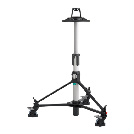
- Page 12 1.1) is a fully-portable pneumatic camera mount, designed to support a payload of up to 30 kg (66 lb) and accept the Vinten lightweight pan and tilt heads. The pedestal has a central telescopic column, part of which may be raised or lowered during operation.
- Page 13 Contents First Previous Next Previous Page Page Page View (22) (21) (20) (19) (18) (17) (16) (13) (15) (12) (10) (13) (11) (14) Fig 1.1 Vision Ped Plus Studio Pedestal...
- Page 14 Contents First Previous Next Previous Page Page Page View Telescopic column The telescopic column consists of: An outer tube An elevation tube A tank assembly Outer tube The outer tube (16) forms the bottom section of the telescopic column. Its lower end fits into the centre casting (12) of the skid assembly, where it is secured by the skid clamp (11).
- Page 15 Contents First Previous Next Previous Page Page Page View valve is set to the 'Pump' position movement of the tank assembly relative to the elevation tube causes the ram cylinder to operate as a pump. When the tank assembly is raised air at atmospheric pressure is drawn into the ram cylinder through a non-return valve in the head of the piston.
-
Page 16: Table Of Contents
Refer to Fig 1.1 to identify the parts. For further operating instructions, please refer to Vision Ped Plus Studio Pedestal Operators Guide, Publication Part No. V3951-4980. Operation Assembling the pedestal... -
Page 17: Column
Contents First Previous Next Previous Page Page Page View (13) (13.1) (14) Fig 2.1 Assembling the skid Column Install the column on the skid as follows: Fully slacken the skid clamp (11) and ensure that the rubber straps on each foot support are to the outside of the foot supports. - Page 18 Contents First Previous Next Previous Page Page Page View Secure each strut to the foot support with the rubber strap (7). Tighten the skid clamp (11) using moderate hand pressure only. The clamp lever has a spring-loaded ratchet-type action and is operated as follows: 3.6.1 Turn the clamp lever clockwise as far as possible.
-
Page 19: Pressurizing The Pedestal
View Pressurizing the pedestal The Vision Ped Plus pedestal may be pressurized using the built-in pump, by using the Vinten Portable Pump or from an external pressure source. Ascertain the payload to be fitted to the pedestal (payload = pan and tilt head, camera, lens and all ancillary equipment). -
Page 20: Pressurizing The Pedestal From An External Pressure Source
Do not attempt to adjust the pressure relief valve. To pressurize the pedestal using the Vinten portable pump, proceed as follows: Fully depress the top stage of the column and engage the safety catch (3). - Page 21 Push the pump plunger fully down, push in the handle release button (P.5) and move the handle (P.1) to the vertical position, where it will lock the pump plunger in the closed position. Fold up both the feet (P.3). (P.5) (P.1) (P.2) (P.4) (P.3) Fig 2.3 The Vinten portable pump...
-
Page 22: Fitting And Balancing The Load
WARNING!: Fit the camera mounting and payload with the moving column depressed and the safety catch (3) engaged. The Vision Ped Plus Pedestal is supplied with a 100mm bowl mount which may be removed to enable the standard four-bolt flat mounting plate to be used. - Page 23 Contents First Previous Next Previous Page Page Page View 13.3 Tighten the bottom clamp (18). 13.4 Remove the load. 13.5 Release the skid clamp (11) and the rubber securing straps (7). Lift the struts clear of the foot supports. 13.6 Use the steering ring (20) to lift the telescopic column vertically until it is clear of the skid assembly, then secure the struts with the retaining strap (6).
- Page 24 Section 3 Tools and Materials Special tools A peg spanner is required for wheel alignment and castor removal. A Vinten tool, Part No. 3319-900SP is available. Consumable materials The following consumable materials are required for certain procedures in Sections 4 and 5.
- Page 25 ............. 12 General The Vision Ped Plus pedestal is robustly made to high engineering standards and little attention is required to maintain serviceability save regular cleaning. Attention to the following points will ensure a long and useful service life with minimum need for repair.
-
Page 26: Routine Checks
WARNING!: Do not exceed a pedestal pressure of 9.6 bar (139 psi). If the safety valve fails to operate before a pressure of 19.6 bar (139 psi) is reached, the pedestal should be repaired by Vinten Broadcast Limited or an authorised service agent. Do not attempt to adjust the pressure relief valve. -
Page 27: Adjustments
Contents First Previous Next Previous Page Page Page View Adjustments Adjustments that may become necessary after considerable use are as follows: Drag control knob adjustment. Taking up wear in the bottom clamp. Taking up wear in the top clamp and skid clamp. Elimination of radial and side play on the top stage. -
Page 28: Taking Up Wear In The Bottom Clamp
Contents First Previous Next Previous Page Page Page View 30° (18) (18.1) (18.2) (18.3) (18.4) Fig 4.1 Drag control knob adjustment Taking up wear in the bottom clamp When applied finger-tight, the ‘V’ notch on the bottom clamp knob(18) should be within the limits shown. -
Page 29: Elimination Of Radial And Side Play In The Moving Column
Contents First Previous Next Previous Page Page Page View Elimination of radial and side play in the moving column There are three sets of two adjustable rollers, mounted one above the other in housings set around the elevation tube, which engage with tracks on the top stage. Grub screws can be used to adjust the bearing shafts inside the roller housing. -
Page 30: Skid Tracking Adjustment
14.2 Engage the track lock (8) on each castor. 14.3 Remove two screws (7.1) from the foot support (7) on the fixed leg and remove the foot support. 14.4 Using a suitable spanner, remove nut (8.1) (A spanner is available from Vinten, Part No. 3319-900SP). - Page 31 Contents First Previous Next Previous Page Page Page View 14.5 Apply Loctite 242 to the nut, re-install and tighten lightly. 14.6 Align the wheel on the fixed leg so that it runs parallel to the leg. 14.7 Using a suitable straight line on the studio floor, check that over a distance of 3.6 m (12 feet) the deviation does not exceed 5 cm (2 in.).
- Page 32 Contents First Previous Next Previous Page Page Page View Section 5 Repair Contents Para General................1 Disassembly Column Separating the telescopic column and...
-
Page 33: Disassembly
Page View NOTE: Certain consumable materials are required for procedures detailed in this Section. Please refer to Tools and Materials (Page 25). For further details, please contact Vinten Broadcast Ltd or your local distributor. Disassembly Column Separating the telescopic column and skid Remove the column from the skid as follows: Lower the top stage and engage the safety catch. -
Page 34: Removing The Top Stage And Elevation Tube From The Outer Tube
Contents First Previous Next Previous Page Page Page View Removing the top stage and elevation tube from the outer tube Remove the top stage and elevation tube from the outer tube as follows: WARNING!: Ensure all pressure is vented before disassembling any part of the telescopic column. -
Page 35: Dismantling The Elevation Tube
Contents First Previous Next Previous Page Page Page View Fully slacken the on-shot clamp (8). Referring to 6.2, remove circlip (15) securing tapered ram in elevation tube (16). Pull the top stage out of the elevation tube. Dismantling the elevation tube Dismantle the elevation tube as follows (Fig 6.3):... -
Page 36: Skid
Contents First Previous Next Previous Page Page Page View Skid Foot supports and castors To remove the foot supports (Fig 6.5): Separate the telescopic column from the skid (Paragraph At each foot support, remove two screws (13) securing foot support (25) to leg tube. If required, pull rubber strap (26) off foot support. -
Page 37: Assembly
Contents First Previous Next Previous Page Page Page View 13.4 Lift out folding legs (23) and collect leg tube lock plungers (9), springs (10), leg tube pads (12) and nylon washers (11). 13.5 Lift out fixed leg (3) which is located in the skid casting by bosses which engage holes in the leg. Assembly Skid Centre casting and leg assemblies... - Page 38 Contents First Previous Next Previous Page Page Page View To assemble the castors (Fig 6.5): 17.1 Unscrew knob (7) and remove screw (17) and two washers (6). 17.2 Slide cable guard (16) on to castor (18). Replace screw (17), two washers (6) and knob (7). 17.3 Degrease thread on castor assembly (19).
- Page 39 ........... 50 Introduction This parts list is issued for the Vision Ped Plus pedestal, manufactured by Vinten Broadcast Limited, Western Way, Bury St. Edmunds, Suffolk, IP33 3TB, England.
-
Page 40: Main Assembly Part Numbers
Page Page View Main assembly part numbers Ensure that the correct serial and part numbers are quoted when ordering main assemblies Assembly Part No. Vision Ped Plus pedestal V3951-0001 Studio skid V3955-0001 Column assembly V3951-1000 100 mm levelling bowl 3330-16... -
Page 41: Fig 6.1 Vision Ped Plus Pedestal
Contents First Previous Next Previous Page Page Page View OSLIGHT_IPO1 Fig 6.1 Vision Ped Plus Pedestal... - Page 42 Contents First Previous Next Previous Page Page Page View Fig 6.1 Vision Ped Plus Pedestal ITEM NOMENCLATURE Top stage (Fig 6.2) Elevation tube (Fig 6.3) Outer tube (Fig 6.4) Skid (Fig 6.5)
-
Page 43: Fig 6.2 Vision Ped Plus Pedestal - Top Stage
Contents First Previous Next Previous Page Page Page View V3951_IPO2 Fig 6.2 Vision Ped Plus Pedestal - Top Stage... - Page 44 Contents First Previous Next Previous Page Page Page View Fig 6.2 Vision Ped Plus Pedestal - Top Stage Item Part No. Nomenclature V3951-2021 Switchover Shaft Operation Label 3328-388 Warning label (icons) M005-401 Screw, flanged, button head, socket, M4 x 8 mm long...
- Page 45 Contents First Previous Next Previous Page Page Page View...
-
Page 46: Fig 6.3 Vision Ped Plus Pedestal - Elevation Tube
Contents First Previous Next Previous Page Page Page View V3951_IPO3 Fig 6.3 Vision Ped Plus Pedestal - Elevation Tube... - Page 47 Contents First Previous Next Previous Page Page Page View Fig 6.3 Vision Ped Plus Pedestal - Elevation Tube Item Part No. Nomenclature V3951-1003 Tank assembly (Fig 6.2) V3951-2010 Gas strut V3951-2025 Tank tube clamp 3320-233 Tube clamp pad M006-812 Screw, grub, dog point, socket head, M5 x 8 mm long...
-
Page 48: Fig 6.4 Vision Ped Plus Pedestal - Outer Tube
Contents First Previous Next Previous Page Page Page View V3951_IPO4 Fig 6.4 Vision Ped Plus Pedestal - Outer Tube... - Page 49 Contents First Previous Next Previous Page Page Page View Fig 6.4 Vision Ped Plus Pedestal - Outer Tube Item Part No. Nomenclature V3951-1002 Top housing assembly V3951-1004 Column Strut Assy M007-816 Screw, grub, cone point, socket head, M6 x 10 mm long...
-
Page 50: Fig 6.5 Vision Ped Plus Pedestal - Skid
Contents First Previous Next Previous Page Page Page View V3955_IPO1 Fig 6.5 Vision Ped Plus Pedestal - Skid... - Page 51 Contents First Previous Next Previous Page Page Page View Fig 6.5 Vision Ped Plus Pedestal - Skid Item Part No. Nomenclature 3423-101 3423-101 V3955-2007 Centre casting upper, Machined V3955-1001 Leg tube assembly (fixed) V3955-2005 Centre casting lower, Machined M006-738 Screw, low-profile, cap head, socket, M5 x 25 mm long L602-122 Washer, plain, small, heavy, 3/8 in.
- Page 52 Contents First Previous Next Previous Page Page Page View...
Need help?
Do you have a question about the Vision Ped Plus and is the answer not in the manual?
Questions and answers