Table of Contents
Advertisement
Quick Links
Advertisement
Table of Contents

Related Manuals for Vinten FHR-35


Summary of Contents for Vinten FHR-35
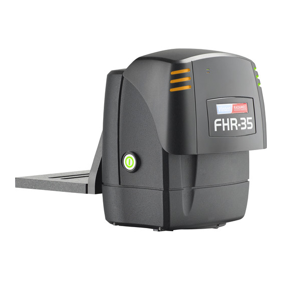
- Page 1 FHR-35 Robotic Pan and Tilt Head Part No. V4096-0001 www.vinten.com...
- Page 2 Original Instructions: English Copyright © 2022 All rights reserved throughout the world. No part of this document may be stored in a retrieval system, transmitted, copied or reproduced in any way, including, but not limited to, photocopy, photograph, magnetic or other record without the prior agreement and permission in writing of the Vitec Group plc.
-
Page 3: Table Of Contents
FHR-35 Robotic Pan and Tilt Head Contents Safety and Warnings ............. . 2 Components and Connections . -
Page 4: Safety And Warnings
If the AC cable is damaged, the product WARNING! The fitting of non-approved parts and must be returned to Vinten Radamec for repair. accessories, or the carrying out of non-approved alterations or servicing can be dangerous and could affect the safety of Basic Electrical Insulation (Class 1 equipment) the product. - Page 5 FHR-35 Robotic Pan and Tilt Head FHR-35 Robotic Pan and Tilt Head Safety and Warnings moves about the pan axis. CAUTION! Do not use oil or grease on any exposed part of the product. This is unnecessary and traps dirt which acts Personnel need to be trained and aware of how far the head and as an abrasive.
-
Page 6: Components And Connections
T i l Components and Connections Front View Rear View 10 ........Camera cradle 1 . -
Page 7: Installation
3 ........USB stick 4 ..... FHR-35 Robotic pan and tilt head 5 . -
Page 8: Mounting Supports And Adaptors
T i l Installation Mounting Supports and Adaptors MOUNTING PART NO. MOUNT SUPPORT OR OPTION ADAPTOR VMA plate AM-VMA-105 HD tripod Wall mounting AM-WBKT-102 Wall bracket Ceiling mounting AM-CEIL-102 Ceiling bracket Adaptor with V4096-1013 Pozi Loc tripod Quickfix groove HD tripod Quickfix adaptor 3490-3 HD tripod... -
Page 9: Cable Management Brackets
Cable Management Brackets Removing the Camera Cradle The FHR-35 is supplied with a cable management bracket fitted The first step in installing the head is to set the mechanical to the base. Camera and head connecting cables can be neatly hard stops to limit the movement of the head about the pan and secured to the bracket providing strain relief for the connectors. -
Page 10: Setting The Pan And Tilt Mechanical Hard Stops
Installation Setting the Pan and Tilt Mechanical Hard Stops The FHR-35 is fitted with adjustable mechanical hard stops that safely restrict the range of movement about the pan and tilt axes. The pan and tilt mountings have a fixed stop and two adjustable stop rings that are locked at the required maximum and minimum limits of movement. -
Page 11: Setting The Tilt Mechanical Hard Stops
FHR-35 Robotic Pan and Tilt Head FHR-35 Robotic Pan and Tilt Head Installation Setting the Tilt Mechanical Hard Stops (a) Place the camera cradle over the tilt mounting. Move the tilt mounting in a clockwise direction to the required maximum limit of movement. -
Page 12: Setting The Pan Mechanical Hard Stops
T i l Installation Setting the Pan Mechanical Hard Stops (a) Move the pan mounting in a counterclockwise direction to the required minimum limit of movement. (b) Move the large outer ring counterclockwise until it rests on the fixed stop. (c) Secure the grub screw into position using a 2.5 mm Allen key. -
Page 13: Ceiling Mounting
FHR-35 Robotic Pan and Tilt Head Installation Ceiling Mounting The FHR-35 can be mounted to the ceiling using either a Mount the head to the ceiling bracket or column. column mount (part no. 196-728-0044) or a bracket (part no. AM-CEIL-102). When mounting the head to a ceiling support, the camera cradle must be inverted. -
Page 14: Wall Mounting
T i l Installation Wall Mounting The FHR-35 can be mounted to a wall using the wall mounting bracket (part no. 196-728-0044). When mounting the head to the wall, the cradle is fitted to the head in the standard position. -
Page 15: Pozi Loc Tripod Mounting Options
FHR-35 Robotic Pan and Tilt Head Installation Pozi Loc Tripod Mounting Options The FHR-35 can be mounted onto the following Pozi Loc tripods: Mount the head to the Pozi Loc tripod using one of the following three mounting options. - Vinten two-stage aluminium EFP Pozi Loc tripod (part no. V4086- 0001). - Page 16 T i l Installation Adaptor with Quickfix Groove (V4096-1013) Using a 5 mm Allen key, attach the adaptor with Quickfix groove to the head using the four M6 screws and washers provided. Mount onto the tripod using either the 150 mm bowl adaptor or the Quickfix 150 mm bowl adaptor.
-
Page 17: Hd Tripod Mounting Options
FHR-35 Robotic Pan and Tilt Head FHR-35 Robotic Pan and Tilt Head Installation HD Tripod Mounting Options The FHR-35 can be mounted onto the following heavy-duty Mount the head to the HD tripod using one of (HD) tripods: the following three mounting options. - Page 18 T i l Installation VMA Plate (AM-VMA-105) Adaptor with Quickfix Groove (V4096-1013) Using a 5/16" Allen key, attach the Using a 5 mm Allen key, attach the VMA plate to the head using the adaptor with Quickfix groove to the six 10-32 screws provided.
-
Page 19: Locking/Unlocking The Camera Cradle
FHR-35 Robotic Pan and Tilt Head FHR-35 Robotic Pan and Tilt Head Installation Locking/Unlocking the Camera Cradle Mounting the Camera Before installing or adjusting the camera or payload, the tilt lock must Using a 4 mm Allen key, be engaged. The tilt lock mechanism holds the camera cradle in the... -
Page 20: Balancing The Head
If the camera cradle stops in a horizontal position (camera pointing directly forward) the balance is correct. The FHR-35 is designed to allow the camera and payload to swing about its own Centre of Gravity (C of G), as opposed to balancing with the use of springs or cams. - Page 21 FHR-35 Robotic Pan and Tilt Head FHR-35 Robotic Pan and Tilt Head Installation If the camera cradle tilts backwards (points upward) then the camera Adjusting the Centre of Gravity (C of G) must be moved towards the front of the head (fore).
-
Page 22: Electrical Connections
Connect the lens interface cable to the lens interface connector on the FHR-35. Tilt the camera cradle through positive and negative angles of travel, checking that the head remains at the angle of tilt it is set to, unsupported. -
Page 23: Cable Management
FHR-35 Robotic Pan and Tilt Head FHR-35 Robotic Pan and Tilt Head Installation Cable Management Powering Up To ensure a safe and tidy installation, all of the cables connected to WARNING! Ensure that all personnel are clear from the the head can be secured neatly using the cable management robotic equipment before powering up. -
Page 24: Maintenance
T i l Maintenance Regular Checks Routine Use During use, check the following: Once a month check the balance of the camera and Ÿ payload and adjust if necessary. No further routine maintenance is required. Cleaning WARNING! Disconnect and isolate the product from the power supply before cleaning. -
Page 25: Troubleshooting
FHR-35 Robotic Pan and Tilt Head FHR-35 Robotic Pan and Tilt Head Troubleshooting Fault Check Action Power supplied, but the camera cradle is Check that the tilt lock is disengaged. See Locking/unlocking the Camera not moving. Cradle Head not operating. -
Page 26: General Notices
Operating temperature range . . 0°C to +50°C (+32°F to +122°F) Vinten HD Quickfix® adaptor ..... . 3490-3 Motor noise ........Minimal Vinten two-stage aluminium EFP Pozi Loc tripod . - Page 27 FHR-35 Robotic Pan and Tilt Head FHR-35 Robotic Pan and Tilt Head...
- Page 28 T i l General Notices Compliance Declaration of Conformity Pollution Degree 2 Vitec Production Solutions Limited declares that this This equipment is designed for operation in Pollution Degree 2 product has been manufactured in accordance with BS environments. EN ISO 9001:2008 and is in compliance with the essential requirements and other relevant provisions of the Machinery Directive 2006/42/EC.
- Page 29 FHR-35 Robotic Pan and Tilt Head FHR-35 Robotic Pan and Tilt Head General Notices General Purpose Connector FHR-35 V4096-0001 The General Purpose Connector can be used to connect a Camera Control Unit (CCU) or for switching and powering other camera FCC Notice accessories.
- Page 32 Publication No. V4096-4980/8 www.vinten.com...
Need help?
Do you have a question about the FHR-35 and is the answer not in the manual?
Questions and answers