Table of Contents
Advertisement
Advertisement
Table of Contents

Related Manuals for Vinten Vision 11


Summary of Contents for Vinten Vision 11
- Page 1 Contents Next Previous Page View Vision 11 Nafl]f Camera Control Solutions...
-
Page 2: Pan And Tilt Head
Vinten Broadcast Limited. Vinten, Vision and Quickfit are registered trademarks of Vinten Broadcast Limited. -
Page 3: Foreword
Particular attention must be paid to cleaning, especially after use in adverse conditions. To order spare parts or to obtain further information, application should be made to Vinten Broadcast Limited or to your local distributor. -
Page 4: Notes To Readers
Page Page View Notes to readers This is the on-line version of ‘Vision 11 Pan and Tilt Head Maintenance Manual’ (3442-9). Readers should be aware that the pagination differs between on-line and printed versions. Navigation Clicking the mouse on any blue text will move you around the document. -
Page 5: Safety - Read This First
Contents First Previous Next Previous Page Page Page View Safety - Read This First! Warning symbols in this maintenance manual Where there is a risk of personal injury, injury to others, or damage to the pan and tilt head or associated equipment, comments appear, highlighted by the word WARNING! and supported by the warning triangle symbol. -
Page 6: Table Of Contents
First Previous Next Previous Page Page Page View Contents Page Foreword ................3 Notes to readers . - Page 7 ..........53 Associated Publication Vision 11 Pan and Tilt Head Operators Guide - Publication Part No. 3442-8...
-
Page 8: Abbreviations
Contents First Previous Next Previous Page Page Page View Abbreviations The following abbreviations are used in this publication: alternating current pound (weight) Amps Lubricated Friction across flats left hand as required MISO metric thread ASME American Society of Mech Engineers metre assy assembly... -
Page 9: Technical Specification
Contents First Previous Next Previous Page Page Page View Technical Specification Weight Head 2.8 kg (6.2 lb) Pan bar 0.4 kg (0.9 lb) Bowl clamp) 0.14 kg (0.3 lblb) Height to mounting face 15 cm (5.9 in.) Length 14 cm (5.5 in.) Width 12.5 cm (4.9 in.) Load capacity... -
Page 10: Design Improvements
Contents First Previous Next Previous Page Page Page View Design Improvements SERIAL No. DETAILS INFORMATION Improved brake knobs 00214 Improved bowl clamp knob 02735 Further improvements to brake knobs 03237... -
Page 11: Vision
(C of G) and may be used to ascertain the suitability of the head for any given combination of camera, lens and accessories. Drag is provided by the Vinten lubricated friction (LF) system which allows wide variation of the drag setting on both pan and tilt axes to suit operator preference, and permits “whip” movements to be executed, irrespective of drag setting. -
Page 12: Fig 1.1 Vision 11 Pan And Tilt Head
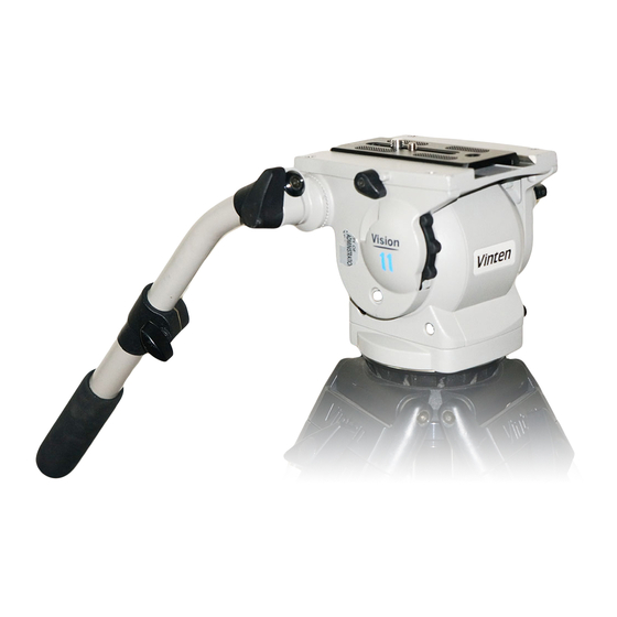
Contents First Previous Next Previous Page Page Page View (16) (15) (14) (13) (12) (11) (10) Fig 1.1 Vision 11 Pan and Tilt Head... - Page 13 Contents First Previous Next Previous Page Page Page View Pan bar mounting points are located at the rear of the head, on either side of the camera mounting platform. A telescopic pan bar is supplied and is attached using a pan bar clamp, with angular adjustment available on the mount serrations.
-
Page 14: General
11 Operators Guide, Publication Part No. 3442-8. Installing the head on a tripod The Vision 11 head is supplied with an integral 100 mm ball mount and is designed for installation on a compatible Vinten Vision tripod. Adaptors are available which enable the heads to be installed on tripods or pedestals fitted with other mountings. -
Page 15: Mounting The Camera (Optional Quickfit Adaptor)
Contents First Previous Next Previous Page Page Page View Mounting the camera (optional Quickfit adaptor) To mount the camera using the optional Quickfit adaptor, proceed as follows (Fig 2.1): If not already attached, secure the Quickfit adaptor (18) to the slide plate (12) with the two screws provided (7). -
Page 16: Balancing The Head
View Balancing the head Balancing the Vision 11 head achieves two objectives. Firstly, when a head is correctly balanced the operator will need a minimum amount of even effort to move the head. Secondly, once balanced, the head and its payload can be set to any tilt position and the head will maintain this position with “hands off”. -
Page 17: Pan And Tilt Brakes
Pan and tilt drag Both the pan and tilt mechanisms incorporate the Vinten lubricated friction (LF) system to ensure smooth movement of the camera about these axes and are fitted with control knobs to adjust the drag setting. Both drag knobs are provided with illuminated scales, graduated from 0 to 9. To illuminate the scales, press the switch (14). -
Page 18: General
Special thumb screw 3441-907TL Assembling pan and tilt drag units NOTE: Adhesives and lubricants are not supplied by Vinten Broadcast Ltd and should be obtained under local arrangements Consumable materials ITEM PART No. Grease, Easyrun 50... -
Page 19: General
..........21 General The Vision 11 pan and tilt head is robustly made to high engineering standards and little attention is required to maintain serviceability save regular cleaning. Attention to the following points will ensure a long and useful life with minimum need for repair. -
Page 20: Routine Checks
All are operated simultaneously by pressing the switch and remain active for approximately 15 seconds. The battery should be replaced yearly or whenever the illumination is considered inadequate. BATTERY TYPE: 9v, 6LR61 (PP3, 6AM6, MN1604, E-BLOCK) Vinten Part No. C550-023 Fig 4.1 Battery Replacement... -
Page 21: Adjustments
Contents First Previous Next Previous Page Page Page View NOTE: The illumination level of the digital display and the level bubble and the drag knob scales varies with the intensity of the ambient light. Removal of the battery will not affect the calibration of the balance mechanism display. WARNING!: If a payload is not fitted to the head, turn the balance knob (15) full counter- clockwise to reduce the balancing force before tilting the head forwards. -
Page 22: Fig 4.2 Brake Knob Adjustment - Earlier Knobs
Contents First Previous Next Previous Page Page Page View 10.1 11.2 60° 10.2 11.3 15° 10.3 11.4 15° 11.1 11.5 Fig 4.2 Brake knob adjustment - earlier knobs... - Page 23 Contents First Previous Next Previous Page Page Page View To install the earlier knob: 11.1 Turn the shaft clockwise, by hand, until the brake is applied. 11.2 Turn the shaft 60° counter-clockwise. 11.3 While still gripping the brake knob stop, push the knob onto the shaft at the 15° position. 11.4 Turn the knob clockwise to the horizontal position.
-
Page 24: Fig 4.3 Brake Knob Adjustment - Later Knobs
Contents First Previous Next Previous Page Page Page View 15.1 16.2 60° 15.2 16.3 15° 15.3 16.4 15° 16.1 16.5 Fig 4.3 Brake knob adjustment - later knobs... -
Page 25: Fig 4.4 Drag Control Knob Adjustment
Contents First Previous Next Previous Page Page Page View Drag control knob adjustment NOTE: The pan and tilt drag control knobs will not normally require adjustment. However, in the event that bedding-in of the mechanism occurs, the knobs should be reset. The procedure shown is for the pan drag knob. -
Page 26: Fig 4.5 Balance Mechanism Digital Display Calibration
Contents First Previous Next Previous Page Page Page View Balance mechanism digital display calibration The digital display indicates setting of the balance mechanism on a scale of 00 (minimum setting) to HI (maximum setting). In the unlikely event of this system requiring calibration, proceed as follows (Fig 4.5): 21.1 Level the platform and apply the tilt brake. -
Page 27: General
..............23 General This section details procedures for disassembly and assembly of the Vision 11 pan and tilt head. Reference is made in the procedures to figures in Section 6 - Illustrated Parts List. -
Page 28: Disassembly
Contents First Previous Next Previous Page Page Page View Disassembly Platform To remove the platform (Fig 6.2): NOTE: Do not remove the slide assembly (46) prior to removing the platform. This will retain the clamping and release components during removal. Remove four screws (7) securing platform (1) to tilt drag unit (13) and tilt brake unit (23). - Page 29 Discard the ‘O’ ring (28). Remove two plugs (8) from the face of the tilt drag housing (25). NOTE: The tilt drag unit assembly contains 12 cc of Vinten Fluid No. 3. Be prepared to catch any fluid that may leak from the assembly.
- Page 30 Contents First Previous Next Previous Page Page Page View Pull the tilt brake disc (3) off the LH side plate (6). If required, remove the bearing (4) from the tilt brake disc. Unscrew and remove the brake shaft (7). Pull the calliper (13) out of its housing, taking care to retain the one outer and two inner brake pads (12, 14).
- Page 31 11.6 Remove the screw (25) and clamp washer (24) from the end of the pan shaft. NOTE: The pan drag unit assembly contains 16 cc of Vinten Fluid No. 3. Be prepared to catch any fluid that may leak from the assembly.
-
Page 32: Assembly
Contents First Previous Next Previous Page Page Page View 12.5 The digits cover (6) is secured to the mechanism housing (11) using Silcoset. Remove if required. Assembly Electrical system To install the electrical system (Fig 6.6): 13.1 If removed, secure the LED housing (5) to the PCB mounting (2D) using Loctite 405. Position the LED (2E) in the housing. - Page 33 14.16 Install the assembled pan drag knob in the pan drag housing (9) and screw into the drag actuator block (13). 14.17 Using a syringe through the plug holes (23), fill the bowl with 16 cc of Vinten Fluid No. 3. 14.18 Install two plugs (23). Wipe off any excess fluid.
- Page 34 Contents First Previous Next Previous Page Page Page View 16.8 Install a thrust washer (14), the thrust bearing (15) and a second thrust washer (14) in the mechanism housing (44). 16.9 Slide assembled balance knob/adjustment slide/actuator shaft into the mechanism housing/ spring actuator, ensuring slot in adjustment slide is to the left.
- Page 35 19.12 Install the assembled tilt drag mechanism in the mechanism side cover (22). 19.13 Using a syringe through the plug holes (8), fill the bowl with 12 cc of Vinten Fluid No. 3. 19.14 Install two plugs (8). Wipe off any excess fluid.
-
Page 36: Final Assembly
Contents First Previous Next Previous Page Page Page View To install the tilt drag unit: 20.1 Referring to 6.6, thread the battery connector (2G) through the hole in the battery housing (8), then slide the battery housing into position in the mechanism housing (11). 20.2 Connect the wiring from the tilt drag unit (2A) to the connector in the mechanism housing. - Page 37 Contents First Previous Next Previous Page Page Page View 25.4 Hold the indicator (2) stationary and rotate the control knob to the right until drag begins to be felt. 25.5 Turn the indicator to 2. 25.6 Turn the drag control knob (3) and indicator (2) together until the grub screw (4) is accessible.Carefully tighten the grubscrew, adjusting the position of the control knob as necessary so that the grub screw seats correctly in a slot in the indicator and may be screwed fully home.
-
Page 38: Introduction
........55 Introduction This parts list is issued for the Vision 11 pan and tilt head manufactured by VINTEN BROADCAST LIMITED, Western Way, Bury St Edmunds, Suffolk, IP33 3TB, England. -
Page 39: Main Assembly Part Numbers
Main assembly part numbers Please ensure that the correct part number is quoted when ordering main assemblies. Assembly Part No. Vision 11 pan and tilt head - Main unit assembly 3442-11 Pan drag unit assembly 3442-12 Tilt drag unit assembly... -
Page 40: Fig 6.1 Vision 11 Pan And Tilt Head
Contents First Previous Next Previous Page Page Page View V11_IP01 Fig 6.1 Vision 11 Pan and Tilt Head... - Page 41 Contents First Previous Next Previous Page Page Page View Fig 6.1 Vision 11 Pan and Tilt Head Item Part Nomenclature 3442-11 Main unit assembly (Fig 6.2, 6.3, 6.4, 6.5, 6.6) 3219-69 Telescopic pan bar unit (Vision 100) (Fig 6.7) 3330-30 Bowl Clamp Knob Assy., comprising:...
-
Page 42: Fig 6.2 Vision 11 Pan And Tilt Head - Main Unit Assembly
Contents First Previous Next Previous Page Page Page View V11_IP02 Fig 6.2 Vision 11 Pan and Tilt Head - Main Unit Assembly... - Page 43 Contents First Previous Next Previous Page Page Page View Fig 6.2 Vision 11 Pan and Tilt Head - Main Unit Assembly Item Part Nomenclature 3441-208 Platform M801-048 Pin, dowel, 5 mm dia. x 12 mm long 3442-206 Serial number label...
- Page 44 Contents First Previous Next Previous Page Page Page View Fig 6.2 Vision 11 Pan and Tilt Head - Main Unit Assembly (Cont) Item Part Nomenclature 3441-236 Brake shaft (pan) P600-012 Roller, needle, 3 mm x 17.8 mm long 3442-202 Adjustment slide M801-021 Pin, dowel, 6 mm dia.
-
Page 45: Fig 6.3 Vision 11 Pan And Tilt Head - Pan Unit Assembly
Contents First Previous Next Previous Page Page Page View VIS8IP03 Fig 6.3 Vision 11 Pan and Tilt Head - Pan Unit Assembly... - Page 46 Contents First Previous Next Previous Page Page Page View Fig 6.3 Vision 11 Pan and Tilt Head - Pan Unit Assembly Item Part Nomenclature M006-703 Screw, cap head, socket, M5 x 12 mm long 3442-15 Pan drag indicator assembly 3441-20...
-
Page 47: Fig 6.4 Vision 11 Pan And Tilt Head -Tilt Drag Unit Assembly
Contents First Previous Next Previous Page Page Page View V11_IP04 Fig 6.4 Vision 11 Pan and Tilt Head -Tilt Drag Unit Assembly... - Page 48 First Previous Next Previous Page Page Page View Fig 6.4 Vision 11 Pan and Tilt Head - Tilt Drag Unit Assembly Item Part Nomenclature 3442-903SP* RH side plate (spare) M005-734 Screw, low-profile, cap head, socket, M4 x 10 mm long...
-
Page 49: Fig 6.5 Vision 11 Pan And Tilt Head -Tilt Brake Unit Assembly
Contents First Previous Next Previous Page Page Page View V11IP05 Fig 6.5 Vision 11 Pan and Tilt Head -Tilt Brake Unit Assembly... - Page 50 First Previous Next Previous Page Page Page View Fig 6.5 Vision 11 Pan and Tilt Head - Tilt Brake Unit Assembly Item Part Nomenclature M005-901 Screw, countersunk head, socket, M4 x 8 mm long (Fig 6.2) 3442-902SP* Mechanism housing (spare) (Fig 6.2)
-
Page 51: Fig 6.6 Vision 11 Pan And Tilt Head - Electrical Installation
Contents First Previous Next Previous Page Page Page View V11IP06 Fig 6.6 Vision 11 Pan and Tilt Head - Electrical Installation... - Page 52 Contents First Previous Next Previous Page Page Page View Fig 6.6 Vision 11 Pan and Tilt Head - Electrical Installation Item Part Nomenclature 3442-13 Tilt drag unit assembly (Fig 6.2) 3442-19 PCB unit assembly - includes: Tilt drag unit wiring...
-
Page 53: Fig 6.7 Vision 11 Pan And Tilt Head - Pan Bar
Contents First Previous Next Previous Page Page Page View V100IP07 Fig 6.7 Vision 11 Pan and Tilt Head - Pan Bar... - Page 54 Contents First Previous Next Previous Page Page Page View Fig 6.7 Vision 11 Pan and Tilt Head - Pan Bar Item Part Nomenclature 3219-69 Telescopic pan bar, consisting of: M006-113 Screw, csk Pozi hd, M5 x 12 mm lg M606-001...
- Page 55 Contents First Previous Next Previous Page Page Page View Fig 6.8 Vision 11 Pan and Tilt Head - Composite Spare Parts Part No. Nomenclature 3364-900SP Platform slide assembly, comprising: 3364-210 Platform slide Q300-128 Section, rubber, 1.78mm diameter, 124mm long 3170-202...
- Page 56 Contents First Previous Previous Page Page View Fig 6.8 Vision 11 Pan and Tilt Head - Composite Spare Parts (Cont) Part No. Nomenclature 3442-904SP LH side plate (spare), comprising: 3442-215 LH side plate L850-032 Wire thread insert, 5/16 in. BSF...
Need help?
Do you have a question about the Vision 11 and is the answer not in the manual?
Questions and answers