Vinten Vision Ped Plus Operator's Manual
Studio pedestal
Hide thumbs
Also See for Vision Ped Plus:
- Operating instructions manual (142 pages) ,
- Maintenance manual (52 pages)
Table of Contents
Advertisement
Quick Links
Advertisement
Table of Contents

Related Manuals for Vinten Vision Ped Plus


Summary of Contents for Vinten Vision Ped Plus
- Page 1 Plus Vision Ped Vinten Camera Control Solutions...
- Page 2 All rights reserved throughout the world. No part of this document may be stored in a retrieval system, transmitted, copied or reproduced in any way including, but not limited to, photocopy, photograph, magnetic or other record without the prior agreement and permission in writing of Vinten Broadcast Limited. Vinten and Vision are registered trademarks of Vinten Broadcast Limited.
-
Page 3: Safety - Read This First
Vinten distributor (see back cover) or visit our website. For details on maintenance and spare parts, please refer to the Vision Ped Plus Maintenance Manual and Illustrated Parts List (Publication Part No. V3951-4990) This is obtainable from Vinten Broadcast Limited or your local Vinten distributor. -
Page 4: Technical Data
Technical data Payload 30 kg (66 lb) Column weight 8 kg (17.6 lb) Skid weight 5.5 kg (12.1 lb) Total pedestal weight 13.5 kg (29.7 lb) Minimum height to 100 mm bowl adaptor mounting face 75.1 cm (29.6 in.) Maximum height 1to 100 mm bowl adaptor mounting face 159.5 cm (62.8 in.) Minimum height to flat mounting face 63.7 cm (25.1 in.) -
Page 5: Table Of Contents
Parts List ..............21 Associated Publication Vision Ped Plus Pedestal Maintenance Manual and illustrated Parts List... - Page 6 (22) (21) (20) (19) (18) (17) (16) (13) (15) (14) (10) (13) (12) (11) Plus Vision Ped studio pedestal...
- Page 7 100 mm levelling bowl adaptor Control valve Safety catch Tank assembly Elevation tube Velcro strap Foot support and strap Track locking pin Brake (10) Fixed leg (11) Skid clamp (12) Skid centre casting (13) Folding leg (14) Cable guard (15) Cable guard adjustment knob (16) Outer tube...
-
Page 8: Introduction And Description
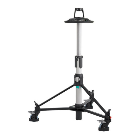
Introduction and Description The Vision Ped Plus studio pedestal is a fully-portable pneumatic camera mount, designed to sup- port a payload of up to 30 kg (66 lb). It comprises a central telescopic column and a skid assembly with castoring wheels. To facilitate transport, the telescopic column and skid may be separated and the skid folded. -
Page 9: Operation
Operation Assembling the pedestal Skid Turn the skid upside-down, depress the leg locking plungers (13.1) and swing each folding leg (13) out until the plungers lock the legs in the fully open position. Set the skid on the ground on its wheels and apply the wheel brakes (9). (13) (13.1) Skid... -
Page 10: Pressurizing The Pedestal
Pressurizing the pedestal The Vision Ped Plus pedestal may be pressurized using the built-in pump, by using the Vinten Portable Pump or from an external pressure source. Ascertain the payload to be fitted to the pedestal (payload = pan and tilt head, camera, lens and all ancillary equipment). - Page 11 The pedestal is fitted with a pressure relief valve as a safeguard against over-pressurization. Do not attempt to adjust the pressure relief valve. To pressurize the pedestal using the Vinten portable pump, proceed as follows: Fully depress the moving column and engage the safety catch (3).
- Page 12 Push the pump plunger fully down, push in the handle release button (P.5) and move the handle (P.1) to the vertical position, where it will lock the pump plunger in the closed posi- tion. Fold up both the feet (P.3). (P.5) (P.1) (P.4) (P.2) (P.3) Vinten portable pump...
-
Page 13: Fitting And Balancing The Load
The Vision Ped Plus pedestal is supplied with a 100mm bowl mount which may be removed to enable the standard four-bolt flat mounting plate to be used. When the camera mount has been secured proceed as follows: Fit the payload to the fully-depressed top stage of the pedestal, ensuring that all items such as pan bars, prompters, lenses etc, are fitted. -
Page 14: Using The Pedestal
ance its payload such that it may be moved to any position over the full on-shot stroke with minimum effort and will maintain its position when the steering ring is released. WARNING! The Schrader valve cap (21) forms a primary pressure seal. Always replace the cap and screw it down finger-tight. - Page 15 Pedestal movement The wheels on the studio version of the skid can be locked in the straight-ahead position or set to castor freely. The castor/lock changeover is effected by spring-loaded track lock pins on each wheel assembly. The pins on the folding legs have black knobs and the pin on the fixed leg has a red knob.
- Page 16 Lower the elevation tube as far as possible. Tighten the bottom clamp (18). Remove the load. Release the skid clamp (11) and the rubber securing straps (7). Lift the struts clear of the foot supports. Use the steering ring to lift the telescopic column vertically until it is clear of the skid assem- bly, then secure the struts with the retaining strap.
-
Page 17: Servicing
Servicing General The Vision Ped Plus pedestal is robustly made to high engineering standards and little attention is required to maintain serviceability save regular cleaning. Attention to the following points will ensure a long and useful service life with minimum need for repair. - Page 18 Bottom clamp adjustment When applied finger-tight, the ‘V’ notch on the bottom clamp knob (18) should be within the limits shown. To adjust the bottom clamp: Remove the hole plug (18.3). Remove the screw (18.2) and washer (18.1) securing knob (18) to the spindle (18.4).
- Page 19 Top clamp and skid clamp adjustment The top clamp (19) and skid clamp (11) are applied and released by turning the handle clockwise or counter-clockwise. Both handles have push-on/pull-off type ratchet adjustment. To adjust the top and skid clamps pull the clamp handle away from the spindle, rotate it clockwise and release.
- Page 20 Using a suitable spanner remove nut (8.1) (a spanner is available from Vinten Part No. 3319-900SP). Apply Loctite 242 to the nut, re-install and tighten lightly. Align the wheel on the fixed leg so that it runs parallel to the leg.
-
Page 21: Parts List
Parts List The following list includes the main assemblies, user-replaceable spare parts and optional acces- sories. For further information regarding repair or spare parts, please contact Vinten Broadcast Limited or your local distributor. For information on-line, visit our website at: www.vinten.com...
Need help?
Do you have a question about the Vision Ped Plus and is the answer not in the manual?
Questions and answers