
Related Manuals for Aerotech APR260DR


Summary of Contents for Aerotech APR260DR
-
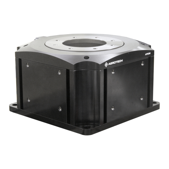
Page 1: Apr260Dr High-Precision Mechanical Bearing Rotary Stage
APR260DR High-Precision Mechanical Bearing Rotary Stage HARDWARE MANUAL Revision 2.00... - Page 2 Global Technical Support Portal for information and support about your Aerotech, Inc. products. The website supplies software, product manuals, Help files, training schedules, and PC-to-PC remote technical support. If necessary, you can complete Product Return (RMA) forms and get information about repairs and spare or replacement parts.
-
Page 3: Table Of Contents
Hardware Manual APR260DR Table of Contents APR260DR High-Precision Mechanical Bearing Rotary Stage Table of Contents List of Figures List of Tables EU Declaration of Incorporation UKCA Declaration of Incorporation Safety Procedures and Warnings Installation and Operation Electrical Warnings Motor-Related Warnings Pinch Points... -
Page 4: List Of Figures
APR260DR Stage Mounting Holes Figure 2-3: Cantilevered Load Capabilities Figure 3-1: Electrical Connections Figure 3-2: APR260DR Motor and Feedback Wiring (-E1, -E2, -E3) Figure 3-3: APR260DR Motor and Feedback Wiring (-E4) Figure 3-4: APR260DR Motor and Feedback Wiring (-E5, -E6) Figure 3-5: Machine Direction... -
Page 5: List Of Tables
APR260DR List of Tables Table 1-1: Model Numbers and Ordering Options Table 1-2: Environmental Specifications Table 1-3: APR260DR Series Specifications Table 2-1: Stage Mounting Surface Flatness Requirement Table 2-2: Stage to Mounting Surface Hardware Table 2-3: Mounting Interface Flatness Requirement... -
Page 6: Eu Declaration Of Incorporation
101 Zeta Drive Pittsburgh, PA 15238-2811 herewith declares that the product: APR260DR stage is intended to be incorporated into machinery to constitute machinery covered by the Directive 2006/42/EC as amended; and that the following harmonized European standards have been applied:... -
Page 7: Ukca Declaration Of Incorporation
101 Zeta Drive Pittsburgh, PA 15238-2811 herewith declares that the product: APR260DR stage To which this declaration relates, meets the essential health and safety requirements and is in conformity with the relevant UK Legislation listed below: Supply of Machinery (Safety) Regulations 2008... -
Page 8: Safety Procedures And Warnings
To find the newest information about this product, refer to www.aerotech.com. If you do not understand the information in this manual, contact Aerotech Global Technical Support. IMPORTANT: This product has been designed for light industrial manufacturing or laboratory environments. -
Page 9: Installation And Operation
Make sure that the product is securely mounted before you operate it. Make sure that all pneumatic lines are securely connected. Use care when you move the APR260DR or you could negatively affect the per- formance of it. WARNING: Trip Hazard! Route, house, and secure all cables, duct work, air, or water lines. -
Page 10: Electrical Warnings
It is the responsibility of the End User/System Integrator to make sure that stages are properly connected and grounded per Engineering Standards and applicable safety requirements. It is the responsibility of the End User/System Integrator to configure the system drive or controller within the Aerotech motor/stage electrical and mechanical specifications. www.aerotech.com... -
Page 11: Motor-Related Warnings
Hardware Manual APR260DR Motor-Related Warnings Aerotech motors are capable of producing high forces and velocities. Obey all warnings and all applicable codes and standards when you use or operate a stage or system that incorporates Aerotech motors. DANGER: Mechanical Hazard! Personnel must be made aware of the mechanical hazards during set up or when you do service to the stage. -
Page 12: Pinch Points
APR260DR Hardware Manual Pinch Points A pinch point is a mechanical hazard that can occur when there are exposed parts of the stage or system that can move. For example, the travel of a stage tabletop could expose the user to a pinch point between the tabletop and the stage housing. -
Page 13: Handling And Storage
Ensure that the antistatic material is not damaged during unpacking. DANGER: Lifting Hazard! Use care when you move the APR260DR or you could negatively affect the performance of it. Use the correct lifting techniques, mechanical assistance, or additional help to lift or move this product. - Page 14 Shipping Brackets If the APR260DR has shipped as part of a system, shipping brackets (typically red, anodized aluminum) might have been installed to secure the system prior to shipment. The shipping clamps, if installed, will need to be removed prior to machine start up.
-
Page 15: Chapter 1: Overview
Hardware Manual APR260DR Chapter 1: Overview Table 1-1: Model Numbers and Ordering Options APR High-Precision Mechanical Bearing Rotary Stage APR260DR-160 APR260DR-180 Feedback (Required) Incremental Encoder: Analog 1 Vpp Incremental Encoder: Digital RS422, x1000 interpolation Incremental Encoder: Digital RS422, x10000 interpolation Absolute Encoder High-Accuracy Incremental Encoder: Digital RS422, x1000 interpolation High-Accuracy Incremental Encoder: Digital RS422, x10000 interpolation... -
Page 16: Environmental Specifications
Indoor use only 1.2. Accuracy and Temperature Effects Aerotech products are designed for and built in a 20°C (68°F) environment. Temperature changes could cause a decrease in performance or permanent damage to the stage. At a minimum, the environmental temperature must be controlled to within 0.25ºC per 24 hours to ensure the stage specifications are repeatable over an extended period of time. -
Page 17: Basic Specifications
(3) Maximum speed listed is stage and motor dependent (and assumes a 340 V bus). The actual speed could be lower due to motor back emf or encoder bandwidth. Consult an Aerotech Applications Engineer for more details. (4) Mass listed is for the standard stage option (no brake and no tabletop). Consult Aerotech for brake and tabletop masses. www.aerotech.com... -
Page 18: Vacuum Operation
6. To reduce outgassing during the initial pump-down to vacuum pressure, Aerotech recommends that you bake out vacuum systems when you first install them into the vacuum chamber. Bake the vacuum components at 60 °C for 24 to 48 hours to desorb water vapor from surfaces and... -
Page 19: Chapter 2: Installation
Chapter 2: Installation The stage installation must be in accordance with the instructions provided by this manual and any accompanying documentation. Failure to follow these instructions could result in injury or damage to the equipment. 2.1. Dimensions Figure 2-1: APR260DR Dimensions www.aerotech.com... -
Page 20: Securing The Stage To The Mounting Surface
Flatness Requirement All Frame Sizes 5 µm APR260DR series stages have a fixed mounting pattern available to secure the stage to a mounting surface. Figure 2-2 shows the main mounting holes in the base of the stage. Tightening torque values for the mounting hardware are dependent on the properties of the surface to which the stage is being mounted. -
Page 21: Figure 2-2: Apr260Dr Stage Mounting Holes
Hardware Manual APR260DR Figure 2-2: APR260DR Stage Mounting Holes www.aerotech.com... -
Page 22: Attaching The Payload Or Fixturing To The Stage
If you start the APR260DR without a payload, the servo gains provided by Aerotech with the shipment may not be appropriate and servo instability can occur. Refer to the controller help file for tuning assistance. -
Page 23: Figure 2-3: Cantilevered Load Capabilities
Hardware Manual APR260DR Figure 2-3: Cantilevered Load Capabilities www.aerotech.com... - Page 24 APR260DR Hardware Manual This page intentionally left blank. www.aerotech.com...
-
Page 25: Chapter 3: Electrical Installation
Aerotech motion control systems are adjusted at the factory for optimum performance. When the APR260DR is part of a complete Aerotech motion control system, setup should only require that you connect the stage to the appropriate drive chassis with the cables provided. Labels on the system components should indicate the appropriate connections. -
Page 26: Motor And Feedback Connectors
IMPORTANT: If you are using standard Aerotech motors and cables, motor and encoder connection adjustments are not required. The protective ground connection of the APR260DR provides motor frame ground protection only. Additional grounding and safety precautions are required for applications requiring access to the stage while it is energized. -
Page 27: Table 3-1: High Power D-Style Motor Connector Pinout
Hardware Manual APR260DR Table 3-1: High Power D-Style Motor Connector Pinout Description Connector Case Shield Connection Motor Phase A Motor Phase B Motor Phase C Reserved Reserved Reserved Reserved Reserved Frame Ground (motor protective ground) Table 3-2: Mating Connector Part Numbers for the Motor Connector... -
Page 28: Table 3-3: Feedback Connector Pinout (-E1, -E2, -E3, -E5, -E6 Options)
APR260DR Hardware Manual The wiring of the feedback connector depends on the encoder option selected (sine wave (analog) or absolute). Table 3-3: Feedback Connector Pinout (-E1, -E2, -E3, -E5, -E6 options) Description Connector Case Shield Connection Reserved Over-Temperature Thermistor Sensor Encoder 5V Supply Input (internally connected to PIN-16) -
Page 29: Table 3-5: Feedback Connector Pinout (-E4 Option)
Hardware Manual APR260DR Table 3-5: Feedback Connector Pinout (-E4 option) Description Connector Case Shield Connection Reserved Over-Temperature Thermistor Sensor Encoder 5V Supply Input (internally connected to PIN-16) Reserved Hall Effect Sensor (Phase B) CLK- (Absolute Encoder Clock-) CLK+ (Absolute Encoder Clock+) -
Page 30: Table 3-7: Secondary Feedback Connector Pinout (-E5 And -E6 Options)
APR260DR Hardware Manual The high-accuracy encoder options include a secondary feedback connector. Table 3-7: Secondary Feedback Connector Pinout (-E5 and -E6 options) Description Connector Case Shield Connection Reserved Reserved 5V Power Supply Input Reserved Reserved MRK- (Encoder Marker-) MRK+ (Encoder Marker+) -
Page 31: Motor And Feedback Wiring
Hardware Manual APR260DR 3.2. Motor and Feedback Wiring Shielded cables are required for the motor and feedback connections. Figure 3-2: APR260DR Motor and Feedback Wiring (-E1, -E2, -E3) www.aerotech.com... -
Page 32: Figure 3-3: Apr260Dr Motor And Feedback Wiring (-E4)
APR260DR Hardware Manual Figure 3-3: APR260DR Motor and Feedback Wiring (-E4) www.aerotech.com... -
Page 33: Figure 3-4: Apr260Dr Motor And Feedback Wiring (-E5, -E6)
Hardware Manual APR260DR Figure 3-4: APR260DR Motor and Feedback Wiring (-E5, -E6) www.aerotech.com... -
Page 34: Motor And Feedback Specifications
APR260DR Hardware Manual 3.3. Motor and Feedback Specifications Hall Effect, Encoder, and Limit wiring share a common 5V supply connection inside the feedback connector. Table 3-9: Hall-Effect Sensor Specifications Specification Supply Voltage 5 V ±5% Supply Current 50 mA Output Type... -
Page 35: Table 3-14: Limit Switch Specifications
High impedance (Logic "1") when in limit Requires external pull-up to +5 V (10 kΩ recommended) Note: If the APR260DR is driven beyond the electrical limit, it will encounter a mechanical stop. Impacting the mechanical stop could cause damage to the stage even at low speeds. -
Page 36: Limits, Marker, And Machine Direction
Hardware Manual 3.4. Limits, Marker, and Machine Direction Aerotech stages are configured to have positive and negative "machine" directions. The machine direction defines the phasing of the feedback and motor signals and is dictated by the stage wiring (refer to Section 3.2.). -
Page 37: Motor And Feedback Phasing
Hardware Manual APR260DR 3.5. Motor and Feedback Phasing Motor phase voltage is measured relative to the virtual wye common point. Figure 3-6: Hall Phasing Diagram www.aerotech.com... -
Page 38: Figure 3-7: Encoder Phasing Reference Diagram (Standard/Square Wave)
APR260DR Hardware Manual Figure 3-7: Encoder Phasing Reference Diagram (Standard/Square Wave) Figure 3-8: Encoder Phasing Reference Diagram (Analog/Sine Wave) www.aerotech.com... -
Page 39: Chapter 4: Maintenance
4.1. Service and Inspection Schedule Inspect the APR260DR at least once per month. The need for a longer or shorter inspection interval will depend on the application and conditions, such as the duty cycle, speed, and environment. -
Page 40: Cleaning And Lubrication
Proper assembly and calibration can only be done at the factory. Contact Aerotech for more information. Cleaning Use isopropyl alcohol on a lint-free cloth to clean any external metal surface of the APR260DR. WARNING: General Hazard Warning! Make sure that all solvent has completely evaporated before you move the stage. -
Page 41: Travel Adjustment
Hardware Manual APR260DR 4.3. Travel Adjustment DANGER: Electrical Shock Hazard! Before you do maintenance to the equipment, disconnect the electrical power. WARNING: Mechanical Hazard! Do not adjust the optical limits to an angle greater than the hard stop travel. Doing so could result in damage to the stage and payload and the possibility of injury. -
Page 42: Figure 4-1: Apr260Dr Limit Flag Adjustment
APR260DR Hardware Manual Figure 4-1: APR260DR Limit Flag Adjustment www.aerotech.com... -
Page 43: Mechanical Hard Stop Adjustments
Stages equipped with the hard stop option (-HS) have the hard stops set at the factory prior to shipment. Although the hard stops are adjustable, contact Aerotech before you change their position because the optical limits could need to be updated. If you change the hard stop position but do not update the optical limits, the stage travel could hit a hard stop and cause damage the stage or payload. -
Page 44: Figure 4-2: Tabletop Screw Locations
APR260DR Hardware Manual Figure 4-2: Tabletop Screw Locations Figure 4-3: Upside Down Assembly Showing Hard Stops www.aerotech.com... -
Page 45: Troubleshooting
Hardware Manual APR260DR 4.4. Troubleshooting Table 4-1: Troubleshooting Symptom Possible Cause and Solution Shipping restraints still installed. Remove the red anodized shipping brackets. Brake not released (if equipped with brake; refer to stage documentation). Stage will not move In Limit condition. Check limits (refer to... - Page 46 APR260DR Hardware Manual This page intentionally left blank. www.aerotech.com...
-
Page 47: Appendix A: Warranty And Field Service
All Other Repairs - After Aerotech's evaluation, the buyer shall be notified of the repair cost. At such time the buyer must issue a valid purchase order to cover the cost of the repair and freight, or authorize the product(s) to be shipped back as is, at the buyer's expense. - Page 48 Aerotech's approval. On-site Warranty Repair If an Aerotech product cannot be made functional by telephone assistance or by sending and having the customer install replacement parts, and cannot be returned to the Aerotech service center for...
-
Page 49: Appendix B: Revision History
Hardware Manual APR260DR Appendix B: Revision History Revision General Information Product update Updated safety information 2.00 Updated EU Declaration of Incorporation Added UKCA Declaration of Incorporation 1.02.00 Product update 1.01.00 Full review/revision 1.00.00 New manual www.aerotech.com... - Page 50 APR260DR Hardware Manual This page intentionally left blank. www.aerotech.com...
-
Page 51: Index
APR260DR Hardware Manual Index Index Humidity Inspection Schedule 2006/42/EC isopropyl alcohol Accuracy and Temperature Effects label 13-14 Accuracy of the Ballscrew Limit Switch Specifications Altitude lubricant Ambient Temperature vacuum Attaching the Payload Motor-Related Warnings Braycote® 602EF mounting surface cleaning 20,22... - Page 52 Index APR260DR Hardware Manual Specifications Encoder Hall-Effect Sensors Limit Switch Thermistor Specifications stabilizing stage stage distortion stabilizing Storage Symptom Table of Contents Temperature Effects Thermistor Specifications Troubleshooting vacuum guidelines vacuum lubricant (Braycote 602EF) Vacuum Operation Vibration Warnings Warranty and Field Service...
Need help?
Do you have a question about the APR260DR and is the answer not in the manual?
Questions and answers