
Related Manuals for Aerotech ABRT Series


Summary of Contents for Aerotech ABRT Series
- Page 1 ABRT Series Stage User’s Manual P/N: EDS126 (Revision 1.04.00) Dedicated to the Science of Motion Aerotech, Inc. 101 Zeta Drive, Pittsburgh, PA, 15238 Phone: 412-963-7470 Fax: 412-963-7459 www.aerotech.com...
- Page 2 June 10, 2009 Revision 1.02.00 January 5, 2009 Revision 1.01.00 March 10, 2008 Revision 1.00.00 September 4, 2007 Product names mentioned herein are used for identification purposes only and may be trademarks of their respective companies. © Aerotech, Inc. 2011...
-
Page 3: Table Of Contents
ABRT Series Stage User's Manual Table of Contents Table of Contents Table of Contents List of Figures List of Tables Chapter 1: Overview 1.1. Standard Features 1.1.1. Optional Features 1.1.2. Model Numbers 1.2. Dimensions 1.3. Safety Procedures and Warnings 1.4. EC Declaration of Incorporation Chapter 2: Installation 2.1. - Page 4 Table of Contents ABRT Series Stage User's Manual www.aerotech.com...
-
Page 5: List Of Figures
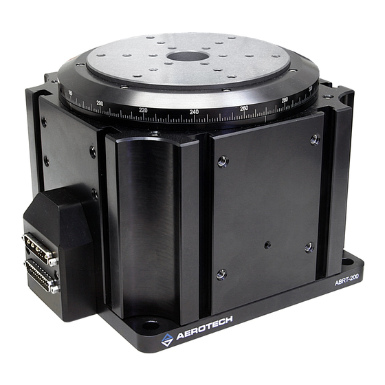
ABRT Series Stage User's Manual List Of Figures List of Figures Figure 1-1: Standard ABRT-200 Rotary Stage Figure 1-2: ABRT-150 Dimensions Figure 1-3: ABRT-200 Dimensions Figure 1-4: ABRT-260 Dimensions Figure 2-1: Results of Flat Versus Non-Flat Mounting Figure 2-2: Top View of an ABRT-200P Stage Showing Mounting Holes... - Page 6 List of Figures ABRT Series Stage User's Manual www.aerotech.com...
-
Page 7: List Of Tables
ABRT Series Stage User's Manual List of Tables List of Tables Table 1-1: Model Numbering System Table 3-1: Environmental Specifications Table 3-2: ABRT Series Specifications Table 3-3: ABRT Series Resolution Information Table 3-4: ABRT Series Maximum Encoder Frequency Table 3-5:... - Page 8 List of Tables ABRT Series Stage User's Manual viii www.aerotech.com...
-
Page 9: Chapter 1: Overview
ABRT Series Stage User's Manual Overview Chapter 1: Overview This chapter introduces standard and optional features of the ABRT stages, explains the model numbering system, and gives general safety precautions. 1.1. Standard Features All ABRT stages stages incorporate completely non-contact air bearing surfaces, direct drive brushless motors and feedback devices to provide a completely maintenance free stage. -
Page 10: Model Numbers
This designates an ABRT-150 stage with direct drive motor and 1vpp sine wave encoder. Aerotech continually improves its product offerings, and listed options may be superseded at any time. Refer to the most recent edition of the Aerotech Motion Control Product Guide for the most current product infor- mation at www.aerotech.com. -
Page 11: Dimensions
ABRT Series Stage User's Manual Overview 1.2. Dimensions Figure 1-2: ABRT-150 Dimensions www.aerotech.com Chapter 1... - Page 12 Overview ABRT Series Stage User's Manual Figure 1-3: ABRT-200 Dimensions Chapter 1 www.aerotech.com...
- Page 13 ABRT Series Stage User's Manual Overview Figure 1-4: ABRT-260 Dimensions www.aerotech.com Chapter 1...
-
Page 14: Safety Procedures And Warnings
Overview ABRT Series Stage User's Manual 1.3. Safety Procedures and Warnings The following statements apply throughout this manual. Failure to observe these precautions could result in serious injury to those performing the procedures and damage to the equipment. This manual and any additional instructions included with the stage should be retained for the lifetime of the stage. - Page 15 ABRT Series Stage User's Manual Overview Do not expose the stage to environments or conditions outside the specified range of oper- ating environments. Operation in conditions other than those specified can cause damage to the equipment. The stage must be mounted securely. Improper mounting can result in injury and damage to the equipment.
-
Page 16: Ec Declaration Of Incorporation
Overview ABRT Series Stage User's Manual 1.4. EC Declaration of Incorporation Manufactorer: Aerotech, Inc. 101 Zeta Drive Pittsburgh, PA 15238 herewith declares that the product: Aerotech, Inc. ABRT Stage is intended to be incorporated into machinery to constitute machinery covered by the Directive 2006/42/EC as amended;... -
Page 17: Chapter 2: Installation
ABRT Series Stage User's Manual Installation Chapter 2: Installation This chapter describes the installation procedure for the ABRT stage, including handling the stage properly, preparing the mounting surface to accept the stage, securing the stage to the mounting surface, attaching the payload, and making the electrical connections. -
Page 18: Preparing The Mounting Surface
The mounting surface should be flat and have adequate stiffness in order to achieve the maximum per- formance from the ABRT. When an ABRT series stage is mounted to a non-flat surface, the stage can be dis- torted as the mounting screws are tightened. This distortion will decrease the overall accuracy of the stage. -
Page 19: Securing The Stage To The Mounting Surface
2.3. Securing the Stage to the Mounting Surface ABRT series stages have counterbored mounting holes available to secure the stage to a mounting surface. Figure 2-2 shows these mounting holes in the base of the stage. These counterbored holes are designed for 6mm socket head cap screws. - Page 20 Installation ABRT Series Stage User's Manual Figure 2-3: Side View of an ABRT-200 Stage Showing Tapped Mounting Holes Chapter 2 www.aerotech.com...
-
Page 21: Attaching The Payload To The Stage
ABRT Series Stage User's Manual Installation 2.4. Attaching the Payload to the Stage To prevent damage to the stage or parts, test the operation of the stage before any payload is mounted to the stage tabletop. Proceed with the electrical installation and test the motion control system in accordance with the system documentation. -
Page 22: Electrical Installation
Aerotech motion control systems are adjusted at the factory for optimum performance. When the ABRT series stage is part of a complete Aerotech motion control system, setup involves connecting a stage and motor combination to the appropriate drive chassis with the cables provided. Connect the provided cable to the feedback and motor connectors on the stage. -
Page 23: Air Requirements
ABRT Series Stage User's Manual Installation 2.6. Air Requirements The air supply to the air bearing is important for the operation of the system. If compressed air is used, it must be filtered to 0.25 microns, dry to 0ºF dew point, and oil free. If nitrogen is used, it must be 99.99% pure and fil- tered to 0.25 microns. - Page 24 Installation ABRT Series Stage User's Manual Chapter 2 www.aerotech.com...
-
Page 25: Chapter 3: Operating Specifications
ABRT Series Stage User's Manual Operating Specifications Chapter 3: Operating Specifications This chapter contains general technical information about ABRT series stages. Included are basic product specifications, resolution information, and motor wiring diagrams. 3.1. Environmental Specifications The environmental specifications for the ABRT are listed in the following table. -
Page 26: Basic Specifications
ABRT Series Stage User's Manual 3.2. Basic Specifications The ABRT series rotary stage specifications are shown in Table 3-2. Encoder resolution information is given in Table 3-3 and speed limitations are given in Table 3-4. Motor specifications are given in Table 3-5. -
Page 27: Table 3-3: Abrt Series Resolution Information
318 rpm N O N E : The encoders used on all ABRS-series stages come standard with a 40 MHz clock rate. Aerotech can provide slower or faster clock rates to match the controller being used. Consult the factory for more information. -
Page 28: Table 3-5: Abrt Series Motor Specifications
(7) Maximum winding temperature is 100 °C, Thermistor trips at 100 °C (8) Ambient operating temperature range: 0 °C - 25 °C, consult Aerotech for performance in elevated ambient temperatures (9) All Aerotech amplifiers are rated Apk; use torque constant in N-m / Apk when sizing Chapter 3 www.aerotech.com... -
Page 29: Load Capability
ABRT Series Stage User's Manual Operating Specifications 3.3. Load Capability The ABRT rotary stage loading specifications are shown in Table 3-6. Table 3-6: ABRT Series Load Capability ABRT Series ABRT-150 ABRT-200 ABRT-260 Max Load – Axial* 20 kg 40 kg 70 kg Max Load –... -
Page 30: Standard Motor Wiring
Connector pinouts and general wiring infor- mation for this special ABRT feedback cable are given in Table 3-8. N O T E : Refer to the other documentation accompanying your Aerotech equipment. Call your Aerotech rep- resentative if there are any questions on system configuration. -
Page 31: Table 3-8: Special Feedback Cable With Encoder Interface Box
ABRT Series Stage User's Manual Operating Specifications Table 3-8: Special Feedback Cable with Encoder Interface Box Pinout of "To Controller" Connector Description Description SIG SHLD COS-N ENC +5V LMT +5V HALL B SIN-N MKR-N LMT COM & TH- ENC COM... -
Page 32: Vacuum Operation
Operating Specifications ABRT Series Stage User's Manual Table 3-9: Motor Wiring Pinout Descriptions Pin Output Description Cosine. Incremental encoder output; either TTL line driven or amplified sine wave type signal. COS-N Incremental encoder output. Complement of cos. ENC COM + 5 V return for optical encoders (ground). -
Page 33: Chapter 4: Maintenance
Stage repair typically requires that the unit be returned to the fac- tory. Please contact Aerotech Technical Support for more information. 4.2. Cleaning and Lubrication There are no elements of the ABRT series stages that require lubrication. Periodic cleaning to remove dust is recommended. 4.2.1. Recommended Cleaning Solvents Before using a cleaning solvent on any part of the stage, it is recommended that compressed nitrogen or clean, dry air be used to blow away small particles and dust. - Page 34 Maintenance ABRT Series Stage User's Manual Chapter 4 www.aerotech.com...
-
Page 35: Appendix A: Warranty And Field Service
Aerotech makes no warranty that its products are fit for the use or purpose to which they may be put by the buyer, where or not such use or purpose... - Page 36 Aerotech will provide an on-site field service representative in a reasonable amount of time, provided that the customer issues a valid purchase order to Aerotech cov- ering all transportation and subsistence costs. For warranty field repairs, the cus- tomer will not be charged for the cost of labor and material.
-
Page 37: Appendix B: Technical Changes
ABRT Series Stage User's Manual Technical Changes Appendix B: Technical Changes Table B-1: Current Changes (1.04.00) Section(s) Affected General Information Section 1.4. Added section Section 3.1. Added section Chapter 2: Installation, Section 2.1. , Added safety information and warnings Section 2.3. , Section 2.5. , and Sec- tion 1.3. -
Page 38: Table B-2: Archived Changes
Technical Changes ABRT Series Stage User's Manual Table B-2: Archived Changes Section(s) Revision Affected General Information 1.03.00 Table 3-2 Unloaded inertia is now 2300 kg/mm (was 2700) Section 1.2. 1.02.00 Dimensions section added Table 3-2 1.01.00 Specifications for the ABRT-150 updated (Stall Torque, Peak Torque, BEMF, and Torque Constant). -
Page 39: Index
Index ABRT Series Stage User's Manual Index Unpacking and Handling the Stage air requirements Attaching the Payload Warnings Cleaning Declaration of Incorporation Dimensions Electrical Installation Environmental Specifications limit switches Lubrication lubrication schedule model numbers Optional Features Preparing the Mounting Surface... - Page 40 ABRT Series Stage User's Manual Index Index www.aerotech.com...
-
Page 41: Reader's Comments
Reader's Comments ABRT Series Stage Manual P/N: EDS126, April 5, 2011 Revision 1.04.00 Please answer the questions below and add any suggestions for improving this doc- ument. Is the manual: Adequate to the subject Well organized Clearly presented Well illustrated How do you use this document in your job? Does it meet your needs? What improvements, if any, would you like to see? Please be specific or cite examples.
Need help?
Do you have a question about the ABRT Series and is the answer not in the manual?
Questions and answers