Table of Contents
Advertisement
Quick Links
Advertisement
Table of Contents

Related Manuals for Aerotech ALAR Series


Summary of Contents for Aerotech ALAR Series
-
Page 1: Alar Large Aperture Rotary Stage
ALAR Large Aperture Rotary Stage HARDWARE MANUAL Revision 1.10.00... - Page 2 Global Technical Support Portal for information and support about your Aerotech, Inc. products. The website supplies software, product manuals, Help files, training schedules, and PC-to-PC remote technical support. If necessary, you can complete Product Return (RMA) forms and get information about repairs and spare or replacement parts.
-
Page 3: Table Of Contents
3.3. Motor and Feedback Specifications 3.4. Limits, Marker, and Machine Direction 3.5. Motor and Feedback Phasing Chapter 4: Maintenance 4.1. Service and Inspection Schedule 4.2. Cleaning 4.3. Troubleshooting Appendix A: Warranty and Field Service Appendix B: Revision History Index www.aerotech.com... -
Page 4: List Of Figures
Motor and Feedback Wiring (-E1 to -E6 Encoder Options) Figure 3-3: Motor and Feedback Wiring (-E7 Encoder Option) Figure 3-4: Machine Direction Figure 3-5: Hall Phasing Figure 3-6: Analog Encoder Phasing Reference Diagram Figure 3-7: Encoder Phasing Reference Diagram (Standard) www.aerotech.com... -
Page 5: List Of Tables
Maximum Speed Per Encoder Option (ALAR-LP) Table 3-13: Maximum Speed Per Encoder Option (ALAR-XP) Table 3-14: ALAR-SP Motor Specifications (ALAR100SP, ALAR150SP, and ALAR200SP) Table 3-15: ALAR-SP Motor Specifications (ALAR250SP and ALAR325SP) Table 3-16: ALAR-LP Motor Specifications Table 3-17: ALAR-XP Motor Specifications www.aerotech.com... - Page 6 List of Tables ALAR Hardware Manual This page intentionally left blank. www.aerotech.com...
-
Page 7: Safety Procedures And Warnings
To find the newest information about this product, refer to www.aerotech.com. If you do not understand the information in this manual, contact Aerotech Global Technical Support. IMPORTANT: This product has been designed for light industrial manufacturing or laboratory environments. - Page 8 Make sure that the product is securely mounted before you operate it. All service and maintenance must be done by approved personnel. WARNING: Securely mount and position all system cables. IMPORTANT: Carefully lift, move, and transport this product. www.aerotech.com...
-
Page 9: Eu Declaration Of Incorporation
ALAR Hardware Manual EU Declaration of Incorporation EU Declaration of Incorporation Aerotech, Inc. 101 Zeta Drive Manufacturer: Pittsburgh, PA 15238-2811 herewith declares that the product: ALAR Stage is intended to be incorporated into machinery to constitute machinery covered by the Directive 2006/42/EC as amended;... - Page 10 EU Declaration of Incorporation ALAR Hardware Manual This page intentionally left blank. www.aerotech.com...
-
Page 11: Chapter 1: Overview
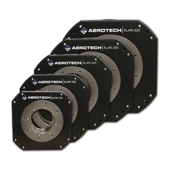
ALAR Hardware Manual Chapter 1: Overview Chapter 1: Overview Table 1-1: Ordering Options ALAR Series Mechanical-Bearing Direct-Drive Rotary Stage ALAR 100SP/LP 100 mm clear aperture ALAR 150SP/LP 150 mm clear aperture ALAR 200SP/LP 200 mm clear aperture ALAR 250SP/LP/XP 250 mm clear aperture... -
Page 12: Environmental Specifications
Indoor use only 1.2. Accuracy and Temperature Effects Aerotech products are designed for and built in a 20°C (68°F) environment. Extreme temperature changes could cause a decrease in performance or permanent damage to the ALAR. At a minimum, the environmental temperature must be controlled to within 0.25ºC per 24 hours to ensure the ALAR specifications are repeatable over an extended period of time. -
Page 13: Basic Specifications
9.7 µrad (2.0 arc sec) 1. Square-wave digital encoder options will limit maximum speed below the listed value. 2. Resolution assumes -E1 encoder with 2000X controller multiplication. 3. Certified with each stage. Requires the use of an Aerotech controller. www.aerotech.com... -
Page 14: Table 1-4: Alar-Sp Series Specifications (Alar250Sp And Alar325Sp)
9.7 µrad (2.0 arc sec) 1. Square-wave digital encoder options will limit maximum speed below the listed value. 2. Resolution assumes -E1 encoder with 2000X controller multiplication. 3. Certified with each stage. Requires the use of an Aerotech controller. www.aerotech.com... -
Page 15: Table 1-5: Alar-Lp Series Specifications (Alar100Lp, Alar150Lp, And Alar200Lp)
2. Resolution assumes -E1 encoder with 2000X controller multiplication. 3. The ALAR-LP base must be fully supported by a rigid mounting plate to achieve this moment load. 4. Certified with each stage. Requires the use of an Aerotech controller. www.aerotech.com... -
Page 16: Table 1-6: Alar-Lp Series Specifications (Alar250Lp And Alar325Lp)
2. Resolution assumes -E1 encoder with 2000X controller multiplication. 3. The ALAR-LP base must be fully supported by a rigid mounting plate to achieve this moment load. 4. Certified with each stage. Requires the use of an Aerotech controller. www.aerotech.com... -
Page 17: Table 1-7: Alar-Xp Series Specifications (Alar250Xp And Alar325Xp)
104 kg 108 kg 129 kg 134 kg Limits 1. Resolution assumes -E1 encoder with 2000X controller multiplication. 2. Certified with each stage. Requires the use of an Aerotech controller. 3. Maximum speed assumes a bus voltage of 320 VDC. www.aerotech.com... -
Page 18: Vacuum Operation
Teflon cables. Aerotech recommends that customers bake out vacuum sys- tems when first installing them in the vacuum chamber. Contact Aerotech to discuss your applic- ation and the recommended bakeout procedure. -
Page 19: Chapter 2: Mechanical Specifications And Installation
Before you operate the ALAR, let it stabilize at room temperature for at least 12 hours. This helps ensure that all of the alignments, preloads, and tolerances are the same as they were when tested at Aerotech. Use compressed nitrogen or clean, dry, oil-free air to remove any dust or debris that has collected during shipping. -
Page 20: Figure 2-1: Alar With Lifting Bolts
2.1. Unpacking and Handling the Stage ALAR Hardware Manual Figure 2-1: ALAR with Lifting Bolts www.aerotech.com... -
Page 21: Dimensions
ALAR Hardware Manual 2.2. Dimensions 2.2. Dimensions Figure 2-2: ALAR100SP Dimensions www.aerotech.com... -
Page 22: Figure 2-3: Alar100Lp Dimensions
2.2. Dimensions ALAR Hardware Manual Figure 2-3: ALAR100LP Dimensions www.aerotech.com... -
Page 23: Figure 2-4: Alar150Sp Dimensions
ALAR Hardware Manual 2.2. Dimensions Figure 2-4: ALAR150SP Dimensions www.aerotech.com... -
Page 24: Figure 2-5: Alar150Lp Dimensions
2.2. Dimensions ALAR Hardware Manual Figure 2-5: ALAR150LP Dimensions www.aerotech.com... -
Page 25: Figure 2-6: Alar200Sp Dimensions
ALAR Hardware Manual 2.2. Dimensions Figure 2-6: ALAR200SP Dimensions www.aerotech.com... -
Page 26: Figure 2-7: Alar200Lp Dimensions
2.2. Dimensions ALAR Hardware Manual Figure 2-7: ALAR200LP Dimensions www.aerotech.com... -
Page 27: Figure 2-8: Alar250Sp Dimensions
ALAR Hardware Manual 2.2. Dimensions Figure 2-8: ALAR250SP Dimensions www.aerotech.com... -
Page 28: Figure 2-9: Alar250Lp Dimensions
2.2. Dimensions ALAR Hardware Manual Figure 2-9: ALAR250LP Dimensions www.aerotech.com... -
Page 29: Figure 2-10: Alar250Xp Dimensions
ALAR Hardware Manual 2.2. Dimensions Figure 2-10: ALAR250XP Dimensions www.aerotech.com... -
Page 30: Figure 2-11: Alar325Sp Dimensions
2.2. Dimensions ALAR Hardware Manual Figure 2-11: ALAR325SP Dimensions www.aerotech.com... -
Page 31: Figure 2-12: Alar325Lp Dimensions
ALAR Hardware Manual 2.2. Dimensions Figure 2-12: ALAR325LP Dimensions www.aerotech.com... -
Page 32: Figure 2-13: Alar325Xp Dimensions
2.2. Dimensions ALAR Hardware Manual Figure 2-13: ALAR325XP Dimensions www.aerotech.com... -
Page 33: Securing The Stage To The Mounting Surface
Keep the use of shims to a minimum when you mount the ALAR to the mounting sur- face. The use of shims could reduce the rigidity of the system. ALAR series stages have a fixed mounting pattern available to secure the stage to a mounting surface. -
Page 34: Figure 2-14: Alar Stage Mounting Holes
2.3. Securing the Stage to the Mounting Surface ALAR Hardware Manual Figure 2-14: ALAR Stage Mounting Holes www.aerotech.com... -
Page 35: Attaching The Payload To The Stage
If the ALAR is started up without a payload, the servo gains provided by Aerotech with the shipment may not be appropriate and servo instability can occur. Refer to the controller help file for tuning assistance. -
Page 36: Travel Adjustment
The internal hard stop is used at the factory to set the electrical and mechanical limit travels. It is not a functional hard stop. Aerotech recommends that you install external hard stops (not supplied) after you receive the stage. The hard stops will need to be designed around application specific parameters such as payload and acceleration. -
Page 37: Electrical Limits
The stage can then continue into the hard stop or do so the next time it is enabled. If you are unsure how to adjust the electrical limit, contact Aerotech for support. ALAR-SP and ALAR-LP: Stages shipped with the -TR340 option can be retrofitted to achieve a different limit travel. -
Page 38: Figure 2-15: Alar Limit Flag Adjustment
2.5.2. Electrical Limits ALAR Hardware Manual Figure 2-15: ALAR Limit Flag Adjustment www.aerotech.com... -
Page 39: Chapter 3: Electrical Specifications And Installation
Aerotech motion control systems are adjusted at the factory for optimum performance. When the ALAR is part of a complete Aerotech motion control system, setup usually involves connecting the ALAR to the appropriate drive chassis with the cables provided. Labels on the system components usually indicate the appropriate connections. -
Page 40: Motor And Feedback Connectors
Stages equipped with standard motors and encoders come from the factory completely wired and assembled. IMPORTANT: Refer to the other documentation that came with your Aerotech equipment. Call your Aerotech representative if there are any questions on system configuration. IMPORTANT: If you are using standard Aerotech motors and cables, motor and encoder connection adjustments are not required. -
Page 41: Table 3-1: 4-Pin Motor Connector Pinout
Reserved Reserved Reserved Reserved Reserved Frame Ground (motor protective ground) Table 3-2: Mating Connector Part Numbers for the Motor Connector Mating Connector Aerotech P/N Third Party P/N Backshell ECK00656 Amphenol #17E-1726-2 Sockets [QTY. 4] ECK00659 ITT Cannon #DM53744-6 Connector ECK00657 ITT Cannon #DBM9W4SA197 www.aerotech.com... -
Page 42: Table 3-3: 25-Pin Feedback Connector Pinout For The -E1 To -E6 Encoder Options
Signal indicating maximum travel limit produced by negative/CCW stage direction Reserved 1. Only available on stages with limit option (otherwise RESERVED). Table 3-4: Mating Connector Part Numbers for the Feedback Connector Mating Connector Aerotech P/N Third Party P/N Backshell ECK00656 Amphenol #17E-1726-2 Connector ECK00300 FCI DB25S064TLF www.aerotech.com... -
Page 43: Table 3-5: 25-Pin Feedback Connector Pinout For The -E7 Encoder Option
Common ground Reserved Reserved Signal indicating stage maximum travel produced by negative/CCW stage direction Reserved Table 3-6: Mating Connector Part Numbers for the Feedback Connector Mating Connector Aerotech P/N Third Party P/N Backshell ECK00656 Amphenol #17E-1726-2 Connector ECK00300 FCI DB25S064TLF www.aerotech.com... -
Page 44: Motor And Feedback Wiring
All motor and controller manufacturers have their own designations for motor phases A/B/C and Hall signals A/B/C (refer to Section 3.5. for motor phasing). Shielded cables are required for the motor and feedback connections. Figure 3-2: Motor and Feedback Wiring (-E1 to -E6 Encoder Options) www.aerotech.com... -
Page 45: Figure 3-3: Motor And Feedback Wiring (-E7 Encoder Option)
ALAR Hardware Manual 3.2. Motor and Feedback Wiring Figure 3-3: Motor and Feedback Wiring (-E7 Encoder Option) www.aerotech.com... -
Page 46: Motor And Feedback Specifications
The stage can then continue into the hard stop or do so the next time it is enabled. Hall effect sensors, encoder and limit switches (if present) are connected to one common 5 VDC supply. Refer to Figure 3-2 or Figure 3-3. www.aerotech.com... -
Page 47: Table 3-8: Alar-Sp Encoder Specifications
2. Resolution assumes 2000X controller multiplication. Table 3-10: ALAR-XP Encoder Specifications Encoder Option ALAR250XP ALAR325XP Fundamental Resolution 64800 76800 (lines/rev) -E1 (arcsec / line) 0.003 0.002 -E6 (arcsec / line) 0.084 -E7 (arcsec / line) 0.0003 0.0003 1. Resolution assumes 2000X controller multiplication.[ALAR; ALAR_ES18247] www.aerotech.com... -
Page 48: Table 3-11: Alar-Sp Maximum Speed Per Encoder Option
90 rpm 90 rpm 120 rpm Table 3-13: Maximum Speed Per Encoder Option (ALAR-XP) Encoder Option ALAR250XP ALAR325XP 180 rpm 100 rpm 134 rpm 100 rpm 180 rpm 100 rpm 1. Digital encoder option (-E6) will limit max speed. www.aerotech.com... -
Page 49: Table 3-14: Alar-Sp Motor Specifications (Alar100Sp, Alar150Sp, And Alar200Sp)
7. Maximum winding temperature is 100 °C (thermistor trips at 100 °C) 8. Ambient operating temperature range 0 °C - 25 °C; consult Aerotech for performance in elevated ambient temperatures 9. All Aerotech amplifiers are rated A ; use torque constant in N·m/A when sizing www.aerotech.com... -
Page 50: Table 3-15: Alar-Sp Motor Specifications (Alar250Sp And Alar325Sp)
7. Maximum winding temperature is 100 °C (thermistor trips at 100 °C) 8. Ambient operating temperature range 0 °C - 25 °C; consult Aerotech for performance in elevated ambient temperatures 9. All Aerotech amplifiers are rated A ; use torque constant in N·m/A when sizing www.aerotech.com... -
Page 51: Table 3-16: Alar-Lp Motor Specifications
7. Maximum winding temperature is 100 °C (thermistor trips at 100 °C) 8. Ambient operating temperature range 0 °C - 25 °C; consult Aerotech for performance in elevated ambient temperatures 9. All Aerotech amplifiers are rated A ; use torque constant in N·m/A when sizing www.aerotech.com... -
Page 52: Table 3-17: Alar-Xp Motor Specifications
5. All performance and electrical specifications ±10% 6. Maximum winding temperature is 100 °C (thermistor trips at 100 °C) 7. Ambient operating temperature range 0 °C - 25 °C; consult Aerotech for performance in elevated ambient temperatures 8. All Aerotech amplifiers are rated A ;... -
Page 53: Limits, Marker, And Machine Direction
3.4. Limits, Marker, and Machine Direction 3.4. Limits, Marker, and Machine Direction Aerotech stages are configured to have positive and negative "machine" directions. The machine direction defines the phasing of the feedback and motor signals and is dictated by the stage wiring (refer to Section 3.2. -
Page 54: Motor And Feedback Phasing
3.5. Motor and Feedback Phasing ALAR Hardware Manual 3.5. Motor and Feedback Phasing Motor phase voltage is measured relative to the virtual wye common point. Figure 3-5: Hall Phasing www.aerotech.com... -
Page 55: Figure 3-6: Analog Encoder Phasing Reference Diagram
ALAR Hardware Manual 3.5. Motor and Feedback Phasing Figure 3-6: Analog Encoder Phasing Reference Diagram Figure 3-7: Encoder Phasing Reference Diagram (Standard) www.aerotech.com... - Page 56 3.5. Motor and Feedback Phasing ALAR Hardware Manual This page intentionally left blank. www.aerotech.com...
-
Page 57: Chapter 4: Maintenance
Before you connect wires to this product, disconnect the electrical power. Restrict access to the stage when it is connected to a power source. The ALAR series stages are designed to require minimum maintenance. 4.1. Service and Inspection Schedule Inspect the ALAR at least once per month. A longer or shorter inspection interval may be required depending on the application and conditions, such as the duty cycle, speed, and environment. -
Page 58: Troubleshooting
Electrical Stage moves Specifications and Installation and Controller documentation). Motor Connections (refer to Electrical Specifications and Installation uncontrollably the Controller documentation). Stage oscillates or Gains misadjusted (refer to the Controller documentation). Encoder signals (refer to the Controller documentation). squeals www.aerotech.com... -
Page 59: Appendix A: Warranty And Field Service
All Other Repairs - After Aerotech's evaluation, the buyer shall be notified of the repair cost. At such time the buyer must issue a valid purchase order to cover the cost of the repair and freight, or authorize the product(s) to be shipped back as is, at the buyer's expense. - Page 60 Aerotech's approval. On-site Warranty Repair If an Aerotech product cannot be made functional by telephone assistance or by sending and having the customer install replacement parts, and cannot be returned to the Aerotech service center for...
-
Page 61: Appendix B: Revision History
ALAR325SP dimensions updated Model Numbering System updated 1.02.00 Socket head cap screw specification changed from 6 mm to M6 Basic Specifications table updated Added clarification on which models contain hall effect limit switches 1.01.00 Dimensions Section added 1.00.00 New Manual www.aerotech.com... - Page 62 Appendix B: Revision History ALAR Hardware Manual This page intentionally left blank. www.aerotech.com...
-
Page 63: Index
ALAR325SP-M2 Specifications Maximum Speed Per Encoder Option ALAR325SP Motor Specifications Motor Specifications ALAR325XP-M1 Specifications ALAR100LP ALAR325XP-M2 Specifications ALAR100SP ALAR325XP Motor Specifications ALAR150LP Altitude ALAR150SP Ambient Temperature ALAR200LP ALAR200SP ALAR250LP Braycote® 602EF ALAR250SP ALAR250XP ALAR325LP ALAR325SP cleaning ALAR325XP mounting surface www.aerotech.com... - Page 64 Index ALAR Hardware Manual mounting surface cleaning securing stage part number Protection Rating protective ground connection serial number solvents stabilizing stage stage distortion stabilizing Table of Contents vacuum guidelines vacuum lubricant (Braycote 602EF) Vibration Warranty and Field Service www.aerotech.com...
Need help?
Do you have a question about the ALAR Series and is the answer not in the manual?
Questions and answers