Festo cpx-fb13 Manual
Terminal cpx, electrical interface, ctel master module, i-port
Hide thumbs
Also See for festo cpx-fb13:
- Manual (167 pages) ,
- Electronic manual (153 pages) ,
- Brief description (62 pages)

Related Manuals for Festo festo cpx-fb13


Summary of Contents for Festo festo cpx-fb13
- Page 1 Terminal CPX Electrical interface CPX‐CTEL‐4‐M12‐5POL Description CTEL master module I-Port 574601 1411a [8041791]...
- Page 2 Essential or useful accessories. Information on environmentally sound usage. Text designations: • Activities that may be carried out in any order. 1. Activities that should be carried out in the order stated. – General lists. Festo – P.BE-CPX-CTEL-EN – 1411a – English...
-
Page 3: Table Of Contents
Address assignment in the CPX system ....... . Festo – P.BE-CPX-CTEL-EN – 1411a – English... - Page 4 ..... . Commissioning with the Festo Maintenance Tool software (CPX-FMT) ....
- Page 5 A list of other descriptions on the components of the CPX or CTEL system as well as an overview of the structure of the CPX terminal user documentation can be found in the CPX system description. Service Please consult your regional Festo contact if you have any technical problems. Festo – P.BE-CPX-CTEL-EN – 1411a – English...
-
Page 6: Safety And Requirements For Product Use
Observe the regulations of the trade associations, German Technical Control Board (TÜV), VDE stipula tions or corresponding national laws and regulations. Festo – P.BE-CPX-CTEL-EN – 1411a – English... -
Page 7: Requirements For Product Use
“Technical data” (è A.1). The product-relevant EC directives can be found in the declaration of con formity. Certificates and the declaration of conformity for this product can be found on the Festo website (è www.festo.com). Festo – P.BE-CPX-CTEL-EN – 1411a – English... -
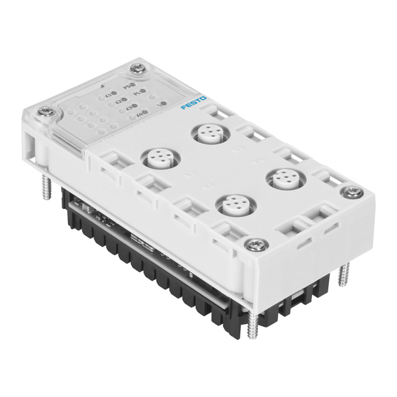
Page 8: System Overview, Ctel System
System overview, CTEL system Overview CTEL system Festo can assist you in solving your automation task at the machine level with the aid of valve terminals and I/O modules. The CTEL master module from Festo permits connection of devices with an I-port interface (I-port devices) to a CPX system. -
Page 9: Mode Of Operation Of The Ctel System
– Relay plates, pressure zone separation plates and blanking plates can also be integrated. I-port input modules – Make available inputs for connecting sensors and enable interrogation of cylinder positions, for example. Other I-port modules Tab. 2.1 Festo – P.BE-CPX-CTEL-EN – 1411a – English... - Page 10 I-port input module I-port input module Fig. 2.2 A constant I/O data exchange takes place through the CTEL master module between the CPX terminal and the devices connected to the CTEL master module. Festo – P.BE-CPX-CTEL-EN – 1411a – English...
-
Page 11: I-Port
The CTEL master module has 4 I-port interfaces. I-port is an interface for the exchange of serial data for the connection of decentralised function modules (devices) from Festo at field level. It is based on the IO-Link technology and is compatible with it in certain areas. -
Page 12: I-Port Interfaces
Tab. 2.2 2.2.3 I-port connecting cables Operation in accordance with specifications is guaranteed only if original Festo connect ing cables are used. For operation in accordance with specifications, the maximum length of the I-port con necting cables must always be observed (è 3.3). -
Page 13: Display Components
– All 4 I-ports are configured to “Port inactive”. Lights up green Load supply voltage present at all connected devices and is OK. Flashes green (approx. 1 Hz) At least one device reports undervoltage PL. Festo – P.BE-CPX-CTEL-EN – 1411a – English... - Page 14 “OK” (LED illuminated green). The I-port at which the error has occurred can be determined through the FMT/MMI using the diagnostic messages. Information on eliminating the displayed errors: è 5.2.2 Diagnostics/error messages by CPX error numbers. Festo – P.BE-CPX-CTEL-EN – 1411a – English...
-
Page 15: Addresses
The I/O lengths listed here are the sum of the bytes available for all I-ports together. Which of these configuration presettings the CTEL master module uses can be determined manually (through the user) or automatically (through the module itself ), dependent on the operating mode. Festo – P.BE-CPX-CTEL-EN – 1411a – English... -
Page 16: Operating Modes (Selection Of The I/O Configuration Presetting)
With the DIL switches 2.1 and 2.2, the I/O length, i.e. the available I/O bytes per I-port, are determined in the manual configuration (è Tab. 2.6). In automatic configuration, the setting of these two switches is not relevant. Festo – P.BE-CPX-CTEL-EN – 1411a – English... - Page 17 8 bytes I/Os (2 bytes per I-port) 16 bytes I/Os (4 bytes per I-port) 24 bytes I/Os (6 bytes per I-port) 32 bytes I/Os (8 bytes per I-port) 1) Standard setting Tab. 2.6 Festo – P.BE-CPX-CTEL-EN – 1411a – English...
-
Page 18: Installation
They will help you avoid damage to the electronics. Note • Handle all modules and components carefully. • Comply with the specified torques. You can obtain information on mounting the CPX terminal in the CPX system description (è P.BECPXSYS…). Festo – P.BE-CPX-CTEL-EN – 1411a – English... -
Page 19: Mounting And Dismantling Of The Module
DIL switches (è 2.5), since they can no longer be reached after mounting. CTEL master module Contact rails Interlinking block (here with additional Screws power supply, as an example) Fig. 3.1 Festo – P.BE-CPX-CTEL-EN – 1411a – English... -
Page 20: I-Port Connecting Cables
(24 V PS and 0 V PS) are energised first. Otherwise, a short circuit might be reported temporarily through the voltage present on the C/Q cable when the connection is created. Festo – P.BE-CPX-CTEL-EN – 1411a – English... -
Page 21: Connection Of The Devices To The Ctel Master Module
A total of up to 4 I-port devices can be connected to one CTEL master module. The devices are connected via Festo I-port connecting cables to the CTEL master module (è 2.1 Overview CTEL system and 3.3 I-port connecting cables). -
Page 22: Connecting The Power Supply
• The total current requirement of the CPX terminal and the CTEL system, as well as the limit values for the maximum current intensities, must be taken into account in the design of the voltage supply (è 3.5.2 Determining the current consumption). Festo – P.BE-CPX-CTEL-EN – 1411a – English... -
Page 23: Determining The Current Consumption
• Observe the notes regarding selection of the power supply unit in the CPX system description (P.BE-CPX-SYS-…). • If you are using I-port output modules with a separate load voltage connection, take into account the corresponding current consumption when selecting a power supply unit. Festo – P.BE-CPX-CTEL-EN – 1411a – English... - Page 24 2) Limit value within a voltage zone, minus the other consumers within the voltage zone Tab. 3.1 An additional power supply of 1.6 A per I-port can be made available through the load voltage supply U Festo – P.BE-CPX-CTEL-EN – 1411a – English...
-
Page 25: Connection With The Host System
2.4.1 I/O configuration presettings. Ensuring protection class IP65/67 Note To comply with protection class IP65/IP67: • Seal unused I-ports with corresponding protective caps (accessories, not included in the scope of delivery (è A.3)). Festo – P.BE-CPX-CTEL-EN – 1411a – English... -
Page 26: Commissioning
Since no individual I/O lengths are possible with the manual configuration, an I/O length of 4 bytes per I-port, that is 16 bytes (for all I-ports together) must be selected (switch S2.1 to “OFF”, S2.2 to “ON”). The configuration presetting selected through this is thus 16 bytes I/16 bytes O. Festo – P.BE-CPX-CTEL-EN – 1411a – English... - Page 27 To make a connection set-up between the CPX terminal and higher-order controller possible, the manu al configuration presetting of the CTEL master module must agree with the respective entry of the cor responding fieldbus configuration file (è 3.6 Connection with the host system). Festo – P.BE-CPX-CTEL-EN – 1411a – English...
-
Page 28: Automatic Configuration
Selection of the configuration presetting: Sum of I/O bytes Configuration presettings 3 bytes I/6 bytes O … 32 bytes I/0 bytes O 8 bytes I/8 bytes O 16 bytes I/16 bytes O … Festo – P.BE-CPX-CTEL-EN – 1411a – English... -
Page 29: Address Assignment In The Cpx System
(LSB). The unused MSBs expire. The distribution of the device addresses to the address space of the CTEL master module in the ex amples from sections 4.1.1 and 4.1.2 would look as follows: Festo – P.BE-CPX-CTEL-EN – 1411a – English... - Page 30 Byte 9 (4 bytes) Byte 2 Byte 10 Byte 3 Byte 11 – Byte 12 I-port 4 – Byte 13 (unused) – Byte 14 – Byte 15 Legend: white = assigned; grey = unused Festo – P.BE-CPX-CTEL-EN – 1411a – English...
- Page 31 (12.5 % of the entire address space in the CPX system). To use the same devices in the manual config uration, 16 bytes I/16 bytes O are needed (25 % of the total address space in the CPX system). Festo – P.BE-CPX-CTEL-EN – 1411a – English...
-
Page 32: Procedure For Commissioning
• Check whether the current consumption of the connected I-port devices and the other CPX modules corresponds to the specifications and limit values (è 3.5 Connecting the power supply). • Check the power supply connections at the interlinking blocks. Festo – P.BE-CPX-CTEL-EN – 1411a – English... -
Page 33: Behaviour In Case Of Malfunctions In Operation
Moreover, additional diagnostic information of the module is available and can be called up both via the fieldbus used as well as via the Festo Maintenance Tool (CPX-FMT) or the operator unit (CPX-MMI). Detailed instructions on the diagnostic functions of the CTEL master module: è... -
Page 34: Notes On Operation
– Double-solenoid valves remain in the current position – Mid-position valves go into mid-position (pressurized, exhausted or closed, depend ing on valve type). • Observe the product specific instructions in the documentation supplied with the valve terminal components. Festo – P.BE-CPX-CTEL-EN – 1411a – English... -
Page 35: Parameter
CTEL I/O mode 00=Automatic config. 01=Only outputs (fixed length) 10=Only inputs (fixed length) 11=I/O (fixed length) CTEL I/O length 00=2 bytes per I-port 01=4 bytes per I-port 10=6 bytes per I-port 11=8 bytes per I-port Festo – P.BE-CPX-CTEL-EN – 1411a – English... -
Page 36: Parameter "Monitoring Uout/Uval
These parameters are read out only during initialization of the CTEL master. Subsequent changes of the parameters have no effects. Bits 0 ... 3 cannot be written in combination with the Festo Maintenance Tool and the operator unit. They are represented in the online mode as read-only parameters. -
Page 37: Parameter "I-Port Configuration
– Expect device This I-port configuration always requires a device connected to the corresponding I-port. An I-port with this I-port configuration must always be connected to a device. Otherwise, an error is output. Festo – P.BE-CPX-CTEL-EN – 1411a – English... -
Page 38: Parameter "Device Parameter I-Port
For each connected device, 8 bytes are available for representation of the device parameters. These parameters are individually interpreted by each device and are defined in the description of the corres ponding device. Festo – P.BE-CPX-CTEL-EN – 1411a – English... -
Page 39: Commissioning With The Operator Unit (Cpx-Mmi)
• Observe the notes on “Force”, “Idle mode” and “Fail safe” in the CPX system de scription and in the description for the operator unit if the CPX bus node used sup ports these parameterisation types. Festo – P.BE-CPX-CTEL-EN – 1411a – English... -
Page 40: Menu Commands Of The Ctel Master Module On The Operator Unit (Cpx-Mmi)
Behaviour after I-port SC: … Device parameter I-port 1: • Byte 1..0: 0x… • Byte 3..2: 0x… • Byte 5..4: 0x… … “Monitoring/forcing” menu (also “Fail safe”) “Parameters” menu (è 4.7.3) (è 4.7.2) Fig. 4.1 Festo – P.BE-CPX-CTEL-EN – 1411a – English... -
Page 41: Observe Signal Statuses (Monitoring)
The “Force” function can also be called up via the “Monitoring ...” menu. This function allows you to force signal statuses during the commissioning phase for test purposes. The same representation of the I-port devices also applies correspondingly to the “Idle mode” and “Fail safe” functions. Festo – P.BE-CPX-CTEL-EN – 1411a – English... -
Page 42: Parameterisation With The Operator Unit (Cpx-Mmi)
Device parameter I-port 1: Byte 1..0: 0x… Byte 3..2: 0x… Byte 5..4: 0x… Byte 7..6: 0x… Device parameter I-port 2: Byte 1..0: 0x… … Parameter CTEL master module Parameter I-port devices Fig. 4.3 Festo – P.BE-CPX-CTEL-EN – 1411a – English... -
Page 43: Commissioning With The Festo Maintenance Tool Software (Cpx-Fmt)
Commissioning Commissioning with the Festo Maintenance Tool software (CPX-FMT) The PC software CPX Festo Maintenance Tool (CPX-FMT) can also be used for commission ing, parameterisation and extended diagnostics of the CTEL master module. You can find the current software version in the Internet (è www.festo.com/sp). -
Page 44: Diagnostics And Error Handling
Advantage: Fast “on-site” error detection; diagnostics also possible from a higher automation level Tab. 5.1 Diagnostics options Note • The available diagnostic information may depend on the settings of the CPX bus node or on the parameterisation. Festo – P.BE-CPX-CTEL-EN – 1411a – English... -
Page 45: Diagnostics/Error Messages
Within a CPX terminal, diagnostics/error messages with reference to inputs have priority over diagnostics/error messages of outputs. This principle of error prioritisation also finds use in the CTEL master module in the I/O mixed operation. Festo – P.BE-CPX-CTEL-EN – 1411a – English... -
Page 46: Diagnostics/Error Messages By Cpx Error Numbers
– Error in memory buffering • Check batteries – Low battery level Maximum value not reached – Device temperature limit exceeded • Check the installation – Primary voltage/main power supply • Check power supply too low Festo – P.BE-CPX-CTEL-EN – 1411a – English... -
Page 47: Diagnostics Via Leds
I-port devices. Description of the LED indicators on the CTEL master module: è 2.3. The significance of the LEDs on the I-port devices can be found in the description of the respective module. Festo – P.BE-CPX-CTEL-EN – 1411a – English... -
Page 48: Diagnostics Via The Cpx Bus Node
I-port devices. The I-port devices connected to a CTEL master module are treated as input or output channels within the CPX terminal. Detailed information on the I/O diagnostic interface and diagnostic memory: è CPX system description (è P.BE-CPX-SYS-…). Festo – P.BE-CPX-CTEL-EN – 1411a – English... -
Page 49: Diagnostics With The Operator Unit (Cpx-Mmi)
… 3: … Module … Module Data (MD) … “Diagnostics” menu Fig. 5.1 General information on operating and commissioning the CPX terminal with the operator unit: è Description for the operator unit (P.BW-CPX-MMI-1-…). Festo – P.BE-CPX-CTEL-EN – 1411a – English... -
Page 50: Diagnostics With The Festo Maintenance Tool (Cpx-Fmt)
Diagnostics and error handling Diagnostics with the Festo Maintenance Tool (CPX-FMT) The Festo Maintenance Tool (CPX-FMT) offers convenient or extended functions that support you in diagnostics and troubleshooting with the CTEL master module. Fig. 5.2 General information on operating and commissioning the CPX terminal with the FMT: è... -
Page 51: Behaviour After Lost Connection To The Device
If input bytes are assigned for the separated module in the CPX system, these are auto matically set to “0”. For existing output bytes, their last known status is saved. Festo – P.BE-CPX-CTEL-EN – 1411a – English... - Page 52 Fixed I/O length 4 bytes Device: 8 bytes I-Port Byte 0 Byte 0 Byte 1 Byte 1 Byte 2 Byte 2 Byte 3 Byte 3 Byte 4 Byte 5 Byte 6 Byte 7 Tab. 5.6 Festo – P.BE-CPX-CTEL-EN – 1411a – English...
-
Page 53: Behaviour With Error At The Pl/Ps Supply
PS or PL, the I-port involved is always switched off completely (PS and PL off ). Behaviour after elimination of the error can be set via the parameter “Behaviour after I-port short cir cuit” (è 4.6.3 Parameter “Behaviour after I-port short circuit”). Festo – P.BE-CPX-CTEL-EN – 1411a – English... -
Page 54: A Technical Appendix
(è CPX system description (P.BE.CPXSYS…)) Recommended minimum voltage PL [V DC] 21.6 (24 – 10 %) ) with operation of devices on I-port connecting cables 5 m Nominal operating voltage [V DC] 24 Festo – P.BE-CPX-CTEL-EN – 1411a – English... - Page 55 4 × sockets M12, 5-pin, A-coded LED indicators Status system supply Status load voltage I-port status/diagnostics Module status Maximum cable length between CTEL master module and device 1) Measurement takes place in CTEL master module Festo – P.BE-CPX-CTEL-EN – 1411a – English...
- Page 56 Module communication error I-port communication error Short-circuit PS/PL Device error Trigger level, undervoltage identification PS Approx. 17.5 Hysteresis undervoltage identification PS [mV] approx. 500 1) Measurement takes place in CTEL master module Tab. A.3 Festo – P.BE-CPX-CTEL-EN – 1411a – English...
-
Page 57: Event Codes
Short circuit – check installation 0x7711 I-port device Mass error – check installation 0x8C00 I-port device Technology-specific application error – device reset 0x8C10 I-port device Process variable range overflow – process data inconsistent Festo – P.BE-CPX-CTEL-EN – 1411a – English... -
Page 58: Accessories
Process variable range underflow – process data inconsistent 0x8C40 I-port device Maintenance required – cleaning 0x8C41 I-port device Maintenance required – refill 0x8C42 I-port device Maintenance required – replace wearing parts Tab. A.4 Accessories Accessories è www.festo.com/catalogue Festo – P.BE-CPX-CTEL-EN – 1411a – English... -
Page 59: B Glossary
Totality of the combined CPX modules, including a bus node, without pneumatics. Device Any module that can be connected to the CTEL master module via the I-port interface. Festo Maintenance Tool. PC software for commissioning, configuration and extended diagnostics of CPX terminals. Digital input I-module Input module I/O length Number of bytes available for inputs and outputs. - Page 60 – via the CPX fieldbus master ... . . – with the Festo Maintenance Tool (FMT) ........
- Page 61 ....– “I-port configuration” ....Festo – P.BE-CPX-CTEL-EN – 1411a – English...
- Page 63 Copyright: Festo AG & Co. KG Postfach 73726 Esslingen Germany Phone: +49 711 347-0 Fax: +49 711 347-2144 e-mail: service_international@festo.com Reproduction, distribution or sale of this document or communica tion of its contents to others without express authorization is Internet: prohibited.
Need help?
Do you have a question about the festo cpx-fb13 and is the answer not in the manual?
Questions and answers