Table of Contents
Advertisement
Advertisement
Table of Contents

Related Manuals for Christie ACT


Summary of Contents for Christie ACT
- Page 1 Christie ACT U S E R M A N U A L 020-100129-05...
- Page 3 Christie ACT U S E R M A N U A L 020-100129-05...
- Page 4 Projector lamps (See Christie’s separate lamp program policy). c. Damage caused by use of a projector lamp beyond the recommended lamp life, or use of a lamp supplied by a supplier other than Christie. d. Problems caused by combination of the product with non-Christie equipment, such as distribution systems, cameras, video tape recorders, etc., or use of the product with any non-Christie interface device.
-
Page 5: Table Of Contents
RS422 With Non-Isolated Power ..................2-10 Expansion ..........................2-10 RS232 Audio ........................2-10 2.5 Installation ...........................2-10 2.5.1 Rack Mount Installation.......................2-10 Installing Christie ACT in a Rack Mount ................2-11 2.5.2 CP 2000 Installation......................2-11 Preparation for CP2000 Installation ..................2-11 Pedestal Installation ......................2-11 Christie ACT User Manual... - Page 6 Status: Interrogator Tab ......................3-6 3.4.4 About Tab ..........................3-6 3.5 User Access and Rights .......................3-7 3.6 Advanced Operation and Configuration ..................3-8 3.6.1 The Christie ACT Design Concept ..................3-8 Actions ..........................3-9 Cues ............................3-9 3.6.2 The Editor Tab ........................3-10 Editor: My Devices Tab ......................3-10 Editor: Script Tab ........................3-11...
- Page 7 4.2.2 Air Filter ..........................4-3 5 Troubleshooting 5.1 Power ............................5-2 5.1.1 Christie ACT Will Not Start ....................5-2 5.1.2 If Christie ACT Loses AC Power ..................5-2 5.1.3 Manually Resetting Christie ACT ..................5-2 5.1.4 Manually Resetting RS-232 IN Port..................5-2 5.2 Ethernet............................5-3 5.3 Input or Relays are Not Functioning ...................5-3 5.3.1 Terminal Block Installation ....................5-3...
- Page 8 Table of Contents Immunity ..........................6-5 Environmental ........................6-5 Christie ACT User Manual 020-100129-05 Rev. 1 (02-2010)
-
Page 9: Introduction
Introduction Christie ACT (Automation Controller) is an independent box that can be used to sequence Christie actions of multiple devices inside or outside of theatre environments. Christie ACT provides a simple user interface for operators, yet provides a rich interface for advanced users that need to configure the unit. -
Page 10: Using This Manual
Every effort has been made to ensure the information in this document is accurate and reliable. However, due to constant research, the information in this document is subject to change without notice. Christie Digital Systems assumes no responsibility for omissions or inaccuracies. -
Page 11: Purchase Record And Service Contacts
Determine the IP Address Using the Serial Port You can determine Christie ACT’s current IP address by connecting to Christie ACT using the RS232 IN port and rebooting Christie ACT (reboot by unplugging the power cord and plugging it back in). As Christie ACT boots up it will display the current Ethernet settings over the serial connection. -
Page 12: Configure The Ip Address Using The Serial Port
The web user interface - a web based interface served internally by Christie ACT and displayed in a web browser over a local area Ethernet network. The web user interface is a full function setup and diagnostic tool that can be used for setup, configuration of “scripts,”... -
Page 13: Key Features
There are 14 relay outputs (28 terminals) all of which are normally open (N/O) single pole single throw (SPST) located on the back panel of Christie ACT. The first 12 are rated for 1A, and the last two are rated for 8A. The external power terminals can be connected to allow the relay outputs to carry some voltage. -
Page 14: List Of Components
Section 1: Introduction 1.3.4 List of Components Ensure you received the following components with your ACT: • ACT with pre-installed ears for rack mounting (2-RU) • 6 ft. power cord • Magnetic “C” Channel Label Holder • Adhesive Rubber Feet •... -
Page 15: Installation And Setup
Installation and Setup This section explains how to install, connect, and get Christie ACT up and running. For operation details, refer to Section 3 Operation. • Section 2.1 General Information • Section 2.2 Front Panel • Section 2.3 Back Panel •... -
Page 16: General Information
Front Panel 2.2.1 Mounting Points Mounting points enable Christie ACT to be installed in the rear of the CP2000 pedestal, or be rack-mounted in a separate standard 19-inch rack. Refer to Section 2.5.1 Rack Mount Installation. -
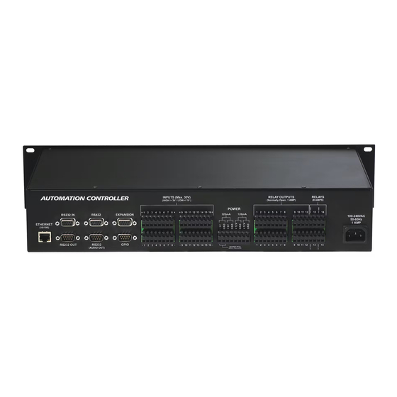
Page 17: Back Panel
Use only the attachments and/or accessories recommended by Christie. Use of others may result in the risk of fire, shock or personal injury. Use the Christie ACT power cord for any installation. Plug into an appropriate wall outlet or use the convenience outlet in the CP2000 pedestal. Christie ACT is rated for 100-240VAC. Refer to Section 6 Specifications for more information. -
Page 18: Power Out
The power outputs are isolated and separate from the main electronics. They are located to the left of the relay outputs, facing the back panel (Figure 2-3). The Christie ACT accepts universal voltages, but includes a North American plug. There are 4 output voltage rails, two 5V, 2W rails and two 12V, 2W rails. These can be connected to the inputs/outputs as desired. - Page 19 Optically Coupled Isolator Optically Coupled Isolator GND on 5V Power Output Terminal Figure 2-6 Inputs ON State The Ground (GND) is shared with Input Pullups Figure 2-7 Inputs With Internal Pull-ups (Active) Christie ACT User Manual 020-100129-05 Rev. 1 (02-2010)
-
Page 20: Gpio
2.4.5 GPIO The 9-pin GPIO male connector is located on the back panel of the Christie ACT. Refer to . It provides a flexible method of interfacing a wide range of external input and output devices to Christie ACT, often so that an event on one device automatically triggers an event on the other. -
Page 21: Relay Outputs
2.4.6 Relay Outputs The relay outputs are located on the back panel of the Christie ACT (Figure 2-2). There are 14 relay outputs (28 terminals) all of which are normally open single pole single throw. The first 12 are rated for 1A, and the last 2 are rated for 8A. -
Page 22: Relay Output Features
2.4.7 USB The USB is located on the front panel of the Christie ACT and is a deferred feature (Figure 2-1). 2.4.8 Ethernet The Ethernet connector is located on the back panel of the Christie ACT (Figure 2-2). The Ethernet connection is capable of 10/100 Base-T with 2 status LEDs. -
Page 23: Serial Port In/Out
3-17. RS232 IN is typically used for incoming signals and RS232 OUT is used by Device Libraries which primarily require outgoing signals, however all of the Christie ACT serial ports are bi-directional. NOTE: Hardware handshaking is not available. For pin identification refer to Figure 2-14. -
Page 24: Rs422 With Non-Isolated Power
This section covers both the Rack Mount and CP2000 Pedestal (optional) installation. 2.5.1 Rack Mount Installation Before installing Christie ACT in a rack mount, the following should be considered: Elevated If installed in a closed or multi-unit rack assembly, the operating ambient temperature of the rack environment may... -
Page 25: Installing Christie Act In A Rack Mount
CAT5 Ethernet cable between your Ethernet controller (or switches) and the Ethernet port on the Christie ACT back panel. Refer to Figure 2-2 for the location of the ethernet port. NOTES: 1) Ethernet crossover cable is not required if connecting directly to a PC. 2) Downloading new software to Christie ACT via Ethernet is supported. -
Page 26: Rs232 Serial Communications
Figure 2-17 Serial Communications The 9-pin RS422 connector is located on the back panel of Christie ACT, refer to Figure 2-17. When using the port, ensure that the baud rate matches that of your RS422 controlling device. Refer to... -
Page 27: Operation
3.9 Using Christie ACT The Christie ACT Web UI is accessed over a local area Ethernet network. The Web UI is a full function setup and diagnostic tool that can be used for setting up Christie ACT, configuring “scripts,” defining button functions, and creating event sequences. -
Page 28: Logging Into Christie Act
Logging into Christie ACT To login to Christie ACT: 1. Open a web browser and type the IP address assigned to your Christie ACT unit (default http:// 192.168.1.89). The Christie ACT Login window appears. NOTE: Internet Explorer V6.0 has known performance issues and is not recommended to be used as the primary web browser for the Christie ACT Web UI. -
Page 29: Viewing A Specific Christie Act
3.4.1 Main Tab The Main tab provides a series of programmable buttons that mimic the front of Christie ACT. There are a series of 14 LED lights that turn ON and OFF depending on the state of the selected button. They are for display only and cannot be turned ON or OFF from this tab. -
Page 30: Operator Tab
Operator buttons extend the system beyond the 8 buttons available on Christie ACT. Buttons are created in the Editor: Operator Buttons tab. You must have the proper permission to create or modify buttons. For more information on adding or editing buttons, refer to Section 3.9.6 Adding an Operator... -
Page 31: Status: State Summary Tab
Status: Execution Summary Tab The Status: Execution Summary tab is a summary of the Cue actions that were executed from the system reset. Refresh the execution summary. Figure 3-8 Status: Execution Summary Tab Christie ACT User Manual 020-100129-05 Rev. 1 (02-2010) -
Page 32: Status: Interrogator Tab
Figure 3-10 About Tab Christie ACT comes with one of two flash boards, 9.1.1 or 9.1.3. The new flash board version number is 9.1.3. To determine the version number, telnet into the machine and run the command cat/proc/hardware. -
Page 33: User Access And Rights
Table 3.1 Permission Levels User Security Levels Access to Tabs... Status Main Any user can view basic Christie ACT status and diagnostic Status information. About Operator Main Operators can view additional operator control buttons. -
Page 34: Advanced Operation And Configuration
Christie ACT is designed to give the application developer (or system integrator) freedom to configure the automation as required for the installation. Christie ACT can be configured to run independently or require user intervention to initiate actions. This is up to the design choices of the application developer. -
Page 35: Actions
Section 3: Operation Actions An action is a command that is executed by Christie ACT. For example, turning LED 1 ON. Actions are output events that Christie ACT sends to external devices. Actions Action Options On/Off/Pulse/Flash Relay Open/Close/Pulse Open/Pulse Close... -
Page 36: The Editor Tab
The Editor tab provides four sub tabs (My Devices, Script, Library, and Operator Buttons) for developing the functionality to automate the device(s) that are connected to Christie ACT. The Editor: My Devices sub tab enables you to create unique devices to be used in scripts. The Editor: Script tab enables you to manage and configure scripts. -
Page 37: Editor: Script Tab
A cue is an input event which allows Christie ACT to perform associated actions. For example, pressing button 1 will result in an event taking place. By adding a cue, you are configuring Christie ACT to respond to an input event. For more information, refer to Section 3.9.5 Adding a Cue to a... -
Page 38: Editor: Library Tab
Export Entire Library - allows you to export the entire library. • Export Selected Device Type - allows you to export a single device type. Highlight the library device you want to export. 3-12 Christie ACT User Manual 020-100129-05 Rev. 1 (02-2010) -
Page 39: Editor: Operator Buttons Tab
The Editor: Operator Buttons tab allows you to create virtual buttons. Each button is associated with a subroutine, which essentially allows Christie ACT to support more cues then it can physically. Once a button is created, it is displayed to the Operator tab. Refer to Section 3.4.2 Operator... -
Page 40: Configuring Christie Act
24 hour format or AM/PM format (default). This can be toggled without requiring re-con- figuration. Time Zone Select your time zone from the list of world time zones. 3-14 Christie ACT User Manual 020-100129-05 Rev. 1 (02-2010) -
Page 41: Config: Network Tab
Section 3: Operation Config: Network Tab The Config: Network tab is used to define or change the Ethernet settings for Christie ACT. Figure 3-17 Config: Network Tab Table 3.6 Summary of Config: Network Tab CONFIG: NETWORK TAB OPTIONS Identification Device Name Name for the device. -
Page 42: Config: Users Tab
NOTES: 1) Do not use capitalization for usernames or passwords. If Capitalization is used for the username or password, Christie ACT will automatically convert it to lower case. 2) Usernames can be a minimum of 4 and maximum of 32 characters. Passwords can be a minimum of 4 and maximum of 128 Characters. -
Page 43: Config: Communication Tab
The Config: Communication tab provides the ability to configure the communication settings on Christie ACT. Configure the direction of each GPIO by toggling each GPIO button between input (I) and output (O). These changes instantly change the pin configuration of the device. You can also enable or disable the internal input pull-up on the opto-isolated inputs by checking the appropriate boxes next to the inputs. -
Page 44: Config: File Management Tab
6. Click the Restore button. Rebooting to Failsafe This reboots Christie ACT into a Failsafe mode which is the first step required when conducting a software upgrade. The Upgrade/Versioning window appears. The Upgrade tab offers 3 buttons which are used during the upgrade process. -
Page 45: Upgrading Christie Act Software
Figure 3-23 Enter Your Christie ACT IP Address in Windows Explorer 7. Drag and drop the upgrade file into the Explorer window. 8. In the Christie ACT Upgrade/Versioning window, click Refresh. The file that was selected appears. 9. Click the file to highlight it and click Upgrade. -
Page 46: Using Christie Act
Warning! 1) DO NOT save a script during a show. Saving a script resets Christie ACT’s script management engine. If Christie ACT is in the middle of running a script and another script is saved, the current active script will be interrupted. 2) DO NOT change or save scripts during a show. -
Page 47: Adding An Action To A Script Or Library
4. Select a specific action from the list to either open a window to configure that action (as in the GPIO shown in Figure 3-26) or to select a predefined action (as in SubroutineName shown in Figure 3-25). Figure 3-26 Adding a Call Action Christie ACT User Manual 3-21 020-100129-05 Rev. 1 (02-2010) - Page 48 6. In the LED Configuration window, click OK to add the action. Relay 1. Select Christie ACT Relay option to open the Relay Configuration window. 2. Click the Relay button to open the Relay window. 3. Highlight the Relay number from the drop-down list (1-14) and click OK.
- Page 49 Termination character window. 6. Highlight the Termination character ([none], <CR>, <LF>, <CR><LF>) from the drop-down list and click OK. 7. In the Serial Msg window, click OK to add action to Christie ACT. Ethernet 1. Select Ethernet to open the Ethernet Msg window.
- Page 50 3. Select an action or cue from the drop-down list that appears. 4. Click OK to select the routine. 5. Click OK a second time to add the selection to Christie ACT. Table 3.11 Editor: My Device Selections (Factory Defaults)
- Page 51 Base Library Status Buzzer [Christie] Short Medium Long 1 2 3 No Go Warning Fire Alarm Loop Buzzer Relays 1 Amp Base Library R1 - R12 [Christie] Masking Flat 1.85 Masking Flat 2.39 Masking Other Lights Up Lights Mid Lights Down Lights All Clear...
- Page 52 Section 3: Operation My Devices Name Library Name Subroutine Options Relays 8 Amp Base Library R13 - R14 [Christie] Latch Relay Hold Latch Relay Clear Slide Relay Hold Slide Relay Clear Slide Relay Toggle ACT Front Panel Base Library Status LEDs [Christie]...
- Page 53 START_SCOPE START_3D FLAT START_3D SCOPE FEATURE CREDITS CUE_1 CUE_2 PROJECTOR_WAKE PROJECTOR_SLEEP Table 3.15 ACT Library Structure (Factory Defaults) OnDeviceStartup SCRIPTS [Fire Marshall] Check Safety Status ACT Buttons Button Definitions [Sample1] Cues LIBRARIES * Cue Library Ethernet [Christie] * Cue Library Serial [Christie]...
-
Page 54: Adding A Device To Mydevices
Warning! DO NOT save a script during a show. Saving a script resets Christie ACT’s script management engine. If Christie ACT is in the middle of running a script and another script is saved, the current active script will be interrupted. - Page 55 1. Enter the signal in the Signal text region. 2. Click OK. Serial 1. Select the Port number from the drop-down list (RS232 IN, RS232 OUT, RS422, RS232 OUT (Audio)). 2. Type the signal. 3. Click OK. Christie ACT User Manual 3-29 020-100129-05 Rev. 1 (02-2010)
-
Page 56: Adding An Operator Button
Device Cues 1. Any cues inside selected Device Libraries will also be available. 2. This includes cues within the ACT Buttons library, the Cues library, and any other devices added to the My Devices page by end-users. 3. If the Library Device Cues already have actions associated (Functional Device Cues), and Library actions associated with this cue will be overridden. -
Page 57: Editing A Script
The user can abort any in progress script by manually resetting the system. This is accomplished by either holding down Buttons #1 and #5 together for 5 seconds on the Christie ACT controller or pressing the Save button in the Editor: Script window. The CUE / READY / ERROR lights will flash ON when the reset has been triggered. -
Page 59: Maintenance
Maintenance Read through this section in it s entirety and understand all warnings and precautions before attempting to operate Christie ACT. This section contains: • 4.1 Safety Warnings and Guidelines • 4.2 Maintaining Proper Cooling Christie ACT User Manual 020-100129-05 Rev. 1 (02-2010) -
Page 60: Safety Warnings And Guidelines
• Do not allow anything to rest on the power cords. Locate the projector where cords cannot be abused by persons walking on it or objects rolling over it. Never operate Christie ACT if the power cable appears damaged in any way. -
Page 61: Maintaining Proper Cooling
4.2.1 Ventilation Mesh side grills provide ventilation. Never block or cover these openings. Do not install the product near a radiator or heat register, or within a small enclosure. Christie ACT does not contain a cooling fan or other cooling mechanism. -
Page 63: Troubleshooting
Troubleshooting If Christie ACT does not appear to be operating properly, note the symptoms present and use the following guide to assist you. If you cannot resolve the problems yourself, contact your dealer for assistance. • 5.1 Power • 5.2 Ethernet •... -
Page 64: Power
1. Check the Ready light that indicates it is powered and started up. 2. Check the status of the LEDs on Christie ACT. If there is no activity (READY not lit) then check the wall circuit breaker to see if it’s ON. -
Page 65: Ethernet
Section 5: Troubleshooting Ethernet 1. Check the Config tab to see if the IP address matches that of Christie ACT. Refer to Section 3.7 Configuring Christie ACT. 2. Make sure the Ethernet settings are valid for your site. All network devices should have the same subnet mask and unique IP addresses. -
Page 67: Specifications
Specifications This section provides detailed Christie ACT specifications including: • 6.1 Performance • 6.2 Power • 6.3 Electrical Interface • 6.4 Physical I/O Connectors • 6.5 Buzzer • 6.6 USB • 6.7 GPIO • 6.8 Regulatory Christie ACT User Manual... -
Page 68: Performance
OVL2 Output voltage 5V (2 W) Reset-able fuse rating (continuous) OVL3 Output voltage 5V (2 W) Reset-able fuse rating (continuous) OVL4 Power isolation voltage 1000 Wire size accept - Clip terminals Gauge Christie ACT User Manual 020-100129-05 Rev. 1 (02-2010) -
Page 69: Electrical Interface
CMax Small relay contact ratings 1 to 12 CMax Large relay contact ratings (continuous A) CMax Large relay contact ratings (resistive) 13 & 14 CMax Wire size accepted - Clip terminals Gauge Christie ACT User Manual 020-100129-05 Rev. 1 (02-2010) -
Page 70: Physical I/O Connectors
Type Piezo Sound pressure level @ 30cm/12VDC Min. 85 dB Figure 6-4 USB USB Full-Speed (12 MBPS) The USB is located on the front panel of Christie ACT and is a deferred feature. Direction Description Signal Name Power Vbus Data -... -
Page 71: Regulatory
Chemicals (REACH) and its amendments. China Ministry of Information Industry Order No.39 (02/2006) on the control of pollution caused by electronic information products, hazardous substances concentration limits (SJ/T11363-2006), and the applicable product marking requirements (SJ/T11364-2006) Christie ACT User Manual 020-100129-05 Rev. 1 (02-2010) - Page 74 Corporate offi ces Worldwide offi ces USA – Cypress United Kingdom Hungary/Eastern Europe Beijing ph: 714-236-8610 ph: +44 118 977 8000 ph: +36 (0) 1 47 48 100 ph: +86 10 6561 0240 Canada – Kitchener Germany Singapore Korea ph: 519-744-8005 ph: +49 2161 664540 ph: +65 6877 8737 ph: +82 2 702 1601...
Need help?
Do you have a question about the ACT and is the answer not in the manual?
Questions and answers