Table of Contents
Advertisement
Quick Links
Advertisement
Table of Contents

Subscribe to Our Youtube Channel
Related Manuals for Alps Electric SC Linear Leak Tester


Summary of Contents for Alps Electric SC Linear Leak Tester
- Page 1 Air Logic Power Systems, LLC 1745 S. 38 Street, Suite 100 Milwaukee, WI. 53215-1732 Phone: 414-671-3332 Fax: 414-671-6645 24 Hour Service Hotline: 800-325-8717 www.alpsleak.com and info@alpsleak.com ALPS SC LINEAR LEAK TESTER QUICK-START GUIDE A beginner’s guide for quick setup and startup.
-
Page 2: Table Of Contents
Copyright © 2012 by Air Logic Power Systems, LLC ..................... i General Information ................................i General Description of the SC Linear Leak Tester machines ................i Machine Designation and Serial Number location ....................i Statement of the intended use for this machinery ....................ii Scope and Limits of Use ............................ - Page 3 AIR LOGIC POWER SYSTEMS (ALPS) TABLE of CONTENTS Home Screen/Main Menu ..............................5 Touch Screen Controls and Menu Overview......................5 Boot Screen ................................5 Home Screen Features Overview ......................... 6 Settings Menu ................................ 7 Guided Setup ..................................8 Guided setup Introduction ............................. 8 Regarding the guided setup tool ...........................
- Page 4 AIR LOGIC POWER SYSTEMS (ALPS) TABLE of CONTENTS Production ..................................26 Stopping and Starting leak Testing ........................26 Emergency Stop Button ............................26 Monitoring Production ............................27 Self Test Procedure ............................27 Alarms Information ............................. 28...
-
Page 5: Notices
Air Logic Power Systems LLC. Software Installation of any new or modification of existing software in the SC Linear Leak Tester not approved by Air Logic Power Systems LLC may adversely affect the operation or performance of the machine and possibly void the warranty and or service agreements. -
Page 6: General Information
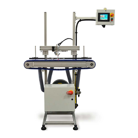
GENERAL INFORMATION General Information General Description of the SC Linear Leak Tester machines The SC model linear machines are designed to test containers for leaks and other defects at speeds up to 180 BPM/CPM (bottles/containers per minute). The speed capability depends on container size, volume, and the sensitivity in leak detection. -
Page 7: Statement Of The Intended Use For This Machinery
AIR LOGIC POWER SYSTEMS (ALPS) GENERAL INFORMATION Statement of the intended use for this machinery ALPS machinery is built solely for the intended purpose of pressure testing plastic containers, bottles, canisters, and seals for leakage. In most instances, this is a precautionary step that is done before the container is filled with product. In instances where the product is pre-packaged, leak testing is done to pressure-test the integrity of the sealing agent. -
Page 8: Wheel-Lock And Mounting Feet Adjustment
AIR LOGIC POWER SYSTEMS (ALPS) GENERAL INFORMATION Wheel-Lock and Mounting Feet Adjustment Position the SC machine on a flat and level area of flooring. The SC machine mounting feet can be adjusted independently (inset) to raise it off the caster wheels to gain stable footing. Use a leveling tool to assure perfect vertical alignment. -
Page 9: Safty
AIR LOGIC POWER SYSTEMS (ALPS) SAFETY SAFTY Safety: Warning Messages Cautions Caution messages can appear before procedures. Messages of this type indicate possible damage to the machine or loss of data if a step or procedure is not properly observed. Warnings Warning messages imply that a potential health hazard exists in the performance of any random procedure WARNING... -
Page 10: Machine Is Installed And Ready For Production
AIR LOGIC POWER SYSTEMS (ALPS) SAFETY Machine is Installed and ready for production Operational Status: Conditional status of the machine A single multi-color light exist on the SC leak tester to indicate the operational status Normal Operation-Green Light The system is built to monitor itself while in normal operational mode. If no Alarm condition exists and the system is in run mode the Green light is illuminated. -
Page 11: Hmi Emergency Stop And Main Air Shut Off
AIR LOGIC POWER SYSTEMS (ALPS) SAFETY HMI Emergency Stop and main Air Shut off COMPONENT FUNCTION Supports conveyor frame, provides guides/clamps for vertical SC Main Enclosure positioning of servo-slide mechanism. SC HMI Menu Display system (Human Machine Interface) Emergency Stop (E-Stop) Immediately stops all activity. -
Page 12: Theory Of Operation
AIR LOGIC POWER SYSTEMS (ALPS) THEORY of OPERATION Theory of Operation Theory of ALPS Leak Testing Start of Leak Test When a container is detected by the SC test photo eye the probe extend and fill valves will execute simultaneously. At this time pressurization of the container occurs. -
Page 13: Theory Of Sc Production Operations
AIR LOGIC POWER SYSTEMS (ALPS) THEORY of OPERATION Theory of SC Production Operations Containers transition from the production line to the SC conveyor for leak testing will be monitored and controlled by various photo eyes, hold and reject cylinders. Caution! Containers not sensed by the photo-eye will not be tested and will be allowed to pass through the machine Test Photo-Eye (PE) The test photo-eye is used for probe positioning on the container for the leak test. -
Page 14: Getting Started
AIR LOGIC POWER SYSTEMS (ALPS) GETTING STARTED: Getting Started If not already accomplished insure the following tasks are complete Control box has a safe and addiquate 120 ACV power source. Plug control box 120 ACV power cord into a clean source of 120 ACV power. 90 PSI Air supply is connected, valve is on and Gauge is set for 60 PSI on. -
Page 15: Sc Quick Start Operations
AIR LOGIC POWER SYSTEMS (ALPS) RS/RSS QUICK START OPERATIONS: SC Quick Start Operations About The Quick Start Manual The SC Quick Start Manual contains procedures and instructions on how to run production in a safe and efficient manner. The SC leak tester is specifically designed to change over from container to container and from job to job. -
Page 16: Home Screen/Main Menu
AIR LOGIC POWER SYSTEMS (ALPS) MAIN MENU: Home Screen/Main Menu Touch Screen Controls and Menu Overview Boot Screen : This screen first appears when the machine is powered up. Pre the bar: GO TO MAIN (HOME) SCREEN. Initial Boot Screen Settings Results Maintenance... -
Page 17: Home Screen Features Overview
AIR LOGIC POWER SYSTEMS (ALPS) MAIN MENU: Home Screen Features Overview 1. Part (container) Pressure Gauge: This gives an indication of the pressure inside of the part during the test. It should be noted that when test cycle times are very fast the refresh rate of the HMI screen may not accurately reflect the actual part pressure. -
Page 18: Settings Menu
AIR LOGIC POWER SYSTEMS (ALPS) MAIN MENU: Settings Menu The SETTINGS menu provides access to basic settings adjustments. These adjustments include fill pressure, test probe settings, T1 and T2 test times, reject settings, and conveyor belt speed settings. It also provides access to basic options as turn ON/OFF Vacuum, Diverter Gate ACCU Height, downed container and reject-verification button. -
Page 19: Guided Setup
AIR LOGIC POWER SYSTEMS (ALPS) GUIDED SETUP Guided Setup Guided setup Introduction Guided setup is a compressive tool that can help the beginning operator setup the SC for leak testing containers. The guided setup will help the operator setup all the necessary leak test and mechanical settings to run containers on the SC machine. -
Page 20: Guided Setup-Mechanical Instructions
AIR LOGIC POWER SYSTEMS (ALPS) GUIDED SETUP Guided Setup continued Proceed to Guided Setup-Navigation Screen. Select . Then press the button. Select the help button utility yields helpful information on how to perform mechanical setup. Guided setup has two options: first the setup () and second: option. -
Page 21: Manual Setup
AIR LOGIC POWER SYSTEMS (ALPS) GUIDED SETUP Manual Guided setup continued Manual Setup Proceed with Mechanical Instructions (Manual Setup) Steps: 1. Setting the Probe Height SS models only. Probe height is adjusted by raising and lowering the probe assembly on the mast until desired height is attained. -
Page 22: Setting Up The Rails
AIR LOGIC POWER SYSTEMS (ALPS) GUIDED SETUP Manual Setup-continued Vertical adjustment and probe height. 2. Setting up the Rails Place a series of containers spaced as shown along the conveyor centerline (illustration). Set the railing to 1/32 “clearance from each container per side. Press the CLOSE/HOME ( ) BUTTON to return to the HOME SCREEN/MAIN MENU. -
Page 23: Setting The Reject Cylinder
AIR LOGIC POWER SYSTEMS (ALPS) GUIDED SETUP Manual Setup-continued 3. Setting the Reject Cylinder The reject cylinder device is attached to the guard rail. The height setting for the Reject device is determined by the height of the guide rail. Horizontal positioning is achieved with an adjustment handle in the guard rail track. -
Page 24: Setting The Hold Cylinder
AIR LOGIC POWER SYSTEMS (ALPS) GUIDED SETUP Manual Setup-continued Setting the Hold Cylinder Turn off incoming air before loosening the hold cylinder. Adjust with a 3/32” Allen wrench. Adjust the hold cylinder only as far as needed to hold back containers. Over adjustment will cause containers to rock or tip prior to testing. - Page 25 AIR LOGIC POWER SYSTEMS (ALPS) GUIDED SETUP Guided Setup-Probe Regulator Setup and Guided Setup Help Probe Regulator Setup If a RED FAIL message appears as shown below, adjust the Probe regulator knob until the black line aligns inside the green area of the pressure gauge. A new screen appears and a PASS message in GREEN appears indicating that the setting is OK.
-
Page 26: Guided Setup-Fill Regulator Setup And Guided Setup Help
AIR LOGIC POWER SYSTEMS (ALPS) GUIDED SETUP Guided Setup-Fill Regulator Setup and Guided Setup Help To perform the Fill Regulator setup, turn off the conveyor and position a known good container under the test head. Press ACTIVATE TEST bar. Minimum and Maximum readings are taken and displayed. The Fill Pressure is then registered below and a pass/fail message will appear in green or red text. -
Page 27: Guided Setup: Reporting Times And Guided Setup Help
AIR LOGIC POWER SYSTEMS (ALPS) GUIDED SETUP Guided Setup: Reporting Times and Guided Setup Help This is a time adjustment override vehicle to fine-tune cycle times in the event that long-necked bottles are being tested. It allows for a longer period of time to pressurize the extended volume of the container. Pressing ( button generates the HELP utility (right). -
Page 28: Set Conveyor Speed
AIR LOGIC POWER SYSTEMS (ALPS) GUIDED SETUP Desired Bottle Speed The following screen is a setup screen for machine running speed. Cycle, FILL, Probe Extend and Retract, and minimum Test 1 (T1) times can be adjusted. Desired running speed (value in gray box) can be changed. Set Conveyor Speed This screen allows you to adjust and set the conveyor belt speed (in feet per minute) using the () buttons to facilitate optimum test conditions. -
Page 29: Fine Tune The Photo-Eye
AIR LOGIC POWER SYSTEMS (ALPS) GUIDED SETUP Fine Tune the Photo-Eye This command allows you to adjust the photo-eye while keeping the system inactive. It allows you to start the system right from the HMI setup screen to test how it works with a series of containers. Pressing ( ) button generates the HELP utility (right). -
Page 30: Ss Guided Setup: Set Reject Position
AIR LOGIC POWER SYSTEMS (ALPS) GUIDED SETUP SS Guided Setup: Set Reject Position This command deals with setting the position of the reject cylinder as the test cycle has completed its run. Pressing ( ) button generates the HELP utility (right). Press NEXT () to move on to Setup Measure, Move and Stop Time. -
Page 31: Setting The T1 Value
AIR LOGIC POWER SYSTEMS (ALPS) GUIDED SETUP Setting the T1 Value This screen displays a breakdown for the Value for T1 (Test 1) as well as definitions for each facet of T1; as measured in thousands of a second. Pressing ( ) button generates the HELP utility (right). -
Page 32: Gather Leak-Test Data
AIR LOGIC POWER SYSTEMS (ALPS) GUIDED SETUP Gather Leak-Test Data Resultant leak test information for a 15 container test run is compiled and displayed as shown. Leak Test Analysis The system has diagnosed leak test data and provided an explanation for any abnormal test readings. Press MORE INFO arrow to advance to next help screen. -
Page 33: Leak Test Analysis-Continued
AIR LOGIC POWER SYSTEMS (ALPS) GUIDED SETUP Leak Test Analysis-continued The system has diagnosed leak test data and provided an explanation for any abnormal test readings. Press MORE INFO arrow to advance to next help screen. ALPS SC LINEAR QUICK-START GUIDE REV00 ©... -
Page 34: End Of Guided Setup: Screens A Thru D
AIR LOGIC POWER SYSTEMS (ALPS) GUIDED SETUP End of Guided Setup: Screens A thru D Pressing ( ) button generates a series of HELP utility screens (right). Each help screen appears in the order shown in the function screen. Function bars inside help screens are inactive. This bar returns back to HOME screen ALPS SC LINEAR QUICK-START GUIDE... -
Page 35: Recipes
AIR LOGIC POWER SYSTEMS RECIPES Recipes Introduction to Recipes A Recipe is a saved file that contains all the necessary test parameters for a particular container... When to Load a Recipe Note: Since guided setup accounts for the required leak test parameters it is not necessary to load a recipe after performing a guided setup. -
Page 36: Load Existing Recipe
AIR LOGIC POWER SYSTEMS RECIPES Load Existing Recipe Select to load an existing recipe. A password prompt will appear. After entering the proper password select a recipe number by touching (0, 1, 2, 3, or 4). Select the download prompt. Do not touch the recipe name. -
Page 37: Production
AIR LOGIC POWER SYSTEMS PRODUCTION Production Stopping and Starting leak Testing Press the lower RED button to temporarily stop leak test production. Press the upper RUN green button to start. Emergency Stop Button The emergency (E-Stop) stop palm button is located on the face of the control box. This immediately shuts down the conveyor belt. -
Page 38: Monitoring Production
AIR LOGIC POWER SYSTEMS PRODUCTION Monitoring Production The Home screen is a useful aid for monitoring overall production concerns. From the Home Screen the latest test results, total accepted/rejected containers and machine speed can be monitored. In addition to this the leak test settings can be verified to ensure they’re set accurately. -
Page 39: Alarms Information
AIR LOGIC POWER SYSTEMS PRODUCTION Alarms Information During production the SC may alarm out and it may be necessary to take certain action. Should this occur please refer to the Warning and Alarms table below. Condition Alarm/Message Solution Machine Stopped No power to machine. - Page 40 AIR LOGIC POWER SYSTEMS PRODUCTION Condition Alarm/Message Solution Machine has stopped This is an alarm setting because of a photo-eye that is designed to detect OFF too long whether the photo-eye is condition/alarm stuck in just the OFF position and probably allowing containers to pass untested.
- Page 41 AIR LOGIC POWER SYSTEMS PRODUCTION Condition Aalarm/Message Solution Machine stops for This alarm indicates the Reject Verification photo-eye has not seen Alarm (failure to see an the container ejected. ejected container). First remove any container in the immediate area (they may have been the container intended to be rejected and wasn’t).
- Page 42 AIR LOGIC POWER SYSTEMS PRODUCTION Condition Alarm/Message Solution Testing still in progress Press the Servo Alarm when the slide bar to reset the servo mechanism reached the alarm. • end of its stroke. Make sure that the conveyor is running as slow as possible.
Need help?
Do you have a question about the SC Linear Leak Tester and is the answer not in the manual?
Questions and answers