Alps Electric Flex Pitch Operator's Manual
Leak tester
Hide thumbs
Also See for Flex Pitch:
- Operator's manual (135 pages) ,
- Quick start manual (35 pages) ,
- Field installation manual (34 pages)

Related Manuals for Alps Electric Flex Pitch


Summary of Contents for Alps Electric Flex Pitch
- Page 1 Operator Manual Flex Pitch Leak Tester Original Instructions [English] 2111241555 Rev A...
- Page 2 Copyright © 2020 ALPS All rights reserved. Printed in the USA. Due to continued product development this information may change without notice. The information and intellectual property contained herein is confidential between ALPS and the client and remains the exclusive property of ALPS. If you find any problems in the documentation, please report them to us in writing.
-
Page 3: Table Of Contents
2.1 Safety Labels ............................ 3 2.2 Cautions and Warnings ......................... 4 2.3 Safety: Warning Messages ......................6 3 Flex Pitch Specifications ......................7 4 Safety-Operational Status/Conditional Status ..............8 4.1 Operational Status: Conditional status of the machine ............8 5 Glossary of Common Terms ..................... 8 6 Introduction to Components ....................10... - Page 4 18 How to Use Inputs and Outputs ..................54 18.1 How to Use Analog Inputs .......................55 18.2 How to Use Digital Inputs......................55 18.3 How to Use Analog Outputs ....................55 18.4 How to Use Digital Outputs .....................55 19 Station Diagnostic overview ....................55 Flex Pitch Operator Manual...
- Page 5 32.9 Averaging/High-Pass Filter .......................77 32.10 Averaging: (AvE) ........................77 32.11 Output Mode (4.out) .......................78 32.12 Output Mode ..........................78 32.13 Set for judgment value (P.V.) ....................78 33 Maintenance Menu ........................79 33.1 Flex Pitch Routine Maintenance Schedule ................80 34 HMI Reference Tables ......................81 34.1 Software............................81 www.alpsleak.com...
- Page 6 35.22 Alarm Counters ........................112 35.23 Setting Options Main ......................113 35.24 Settings Options 1 ........................ 115 35.25 Settings Option 2 ........................117 35.26 Change Container ......................... 119 35.27 Recipes ............................ 121 35.28 Counters ..........................123 Flex Pitch Operator Manual...
- Page 7 www.alpsleak.com...
-
Page 9: Introduction
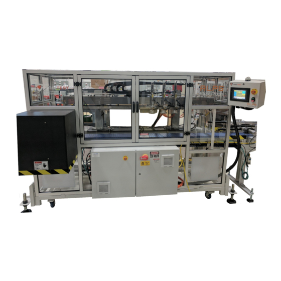
The Flex Pitch has built in flexibility with 2-4 test heads for a variety of container sizes up to 350oz. This makes the Flex Pitch ideal to leak test difficult containers. The Flex Pitch Multi-Moving head leak tester provides tool-less adjustments and no formatted parts to change, making quick container changeovers. -
Page 10: Machine Designation And Serial Number Location
Along with it are the 24-Hour service hotline phone number 1-800-325-8717 and the UL Panel Rating plate. Table 1: Machine Label Locations Label ALPS 24-hour service hotline phone number 1-800-325-8717 Identification and serial number plaque ALPS rating label UL Certification Sticker Flex Pitch Operator Manual... -
Page 11: Safety
2 Safety 2.1 Safety Labels The symbols used on the machine were developed by the International Organization for Standardization (ISO) and are defined below. These symbols may include yellow warnings triangles, blue mandatory action circles, or red prohibited action circles. Symbol Definition High voltage warning... -
Page 12: Cautions And Warnings
CAUTION Read the instructions before using the machine. Only qualified personnel should operate the Flex Pitch. WARNING High pressure hoses, fittings and couplings are important for the safety of the machine. Use only hoses, fittings and couplings recommended by ALPS. - Page 13 2.2.4 Lock Out Tag Out This decal appears prominently next to the main power switch on the side of the High Voltage Control cabinet at the rear of the machine. Lock-out and tag-out procedures are covered in the service and maintenance manual. 2.2.5 Warning! Watch Your Hands and Fingers This warning is seen on the front of the discharge chute.
-
Page 14: Safety: Warning Messages
Warnings: Warning messages imply that a potential health hazard exists in the performance of any random procedure. WARNING Only trained and or certified personnel should operate or rig the Flex Pitch for shipment or movement. Flex Pitch Operator Manual... -
Page 15: Flex Pitch Specifications
3 Flex Pitch Specifications Dimensions W-D-H 101” x 63” x 85” (2566 mm x 1600 mm x 2160 mm) Weight 2000 lbs (9000 kg) Medium (Min/Max up to 8” (203 mm) diameter & 5.5” to 14” (140 mm-355 mm) height. -
Page 16: Safety-Operational Status/Conditional Status
Containers Per Hour/ Containers Per Minute / Containers Per Hour / Containers Per Minute Downstream Photo-Eye Photo-eye that senses a backlog of containers at the exit End of T1 Pressure Test result displays the pressure in the container at the end of Test 1. Flex Pitch Operator Manual... - Page 17 Term Description End of T2 Pressure Test result displays the pressure in the container at the end of Test 2. Fill Pressure The pressure used to fill the container. This pressure is set in PSI. Fill Valve The Solenoid valve that controls the air used to pressurize the container. An acronym meaning: Human Machine Interface.
-
Page 18: Introduction To Components
Consists of a servo motor, that moves the Test Probe Head with the container Electrical Enclosure Contains essential electronics to run the machine E-Stop Flex Pitch Emergency Stop Reject Chute Containers that are rejected will be pushed into the reject chute Airflow shut-off, pressure control and filtration... -
Page 19: Theory Of Operations
7 Theory of Operations 7.1 Leak Test Operations Figure 1: Peak Pressure Chart 7.2 Pressure Test Untested containers are transferred from line conveyor to the FlexPitch. When the FlexPitch begins to detect containers the test-probes will extend to seal and pressurize the containers. The Pressure Test ensures the container reaches the specified Peak Pressure. -
Page 20: Test 2 (T2) (Leak Test)
Detects a failed container and fires the reject cylinder at the appropriate time. It is also Reject Photo Eye used to detect untested containers that may have been missed by the Container Present Photo-eye (issues an Unexpected Container Warning) Flex Pitch Operator Manual... -
Page 21: Emergency Door Sensors Positions
Ref # Photo Eye Function Verifies that rejected containers have left production line. If the sensor fails to detect the Reject Verification/Chute Moni- container, or if the sensor field has not been broken after a reject occurs, the machine tor Photo-Eye and conveyor will shut down and an alarm condition called a Reject Verification Fault is generated. -
Page 22: Hmi Password Protection
Figure 5&6. Pressing the lock icon provides access to obtain operator, supervisor, or technician user privileges. Press the Lock on the top of the menu bar to access keypads and enter user login information. Select the lock to log out when logging out. Flex Pitch Operator Manual... -
Page 23: How To Enter Passwords
10.3 How to Enter Passwords Figure 5: Login Lock for All Screens 1. From any screen, select the lock on the settings navigation menu on the right side of the screen. Figure 6: Basic Password Screen 2. A password prompt screen appears. Touch the white input area. 3. -
Page 24: How To Edit Settings With The Hmi
Boxes that are white can be selected and new values entered. All screens can be viewed and their respective functionality in the HMI Navigation guide in the back of this manual. To access a settings screen, press the settings icon. Flex Pitch Operator Manual... - Page 25 A popup screen will display the various screens the user can access. Figure 11: Popup Navigation Once a screen is selected changes can be made to the Flex Pitch operations. When a setting is selected, a numeric key pad will popup.
- Page 26 Start Fill Time Pressure The point of when a good seal is reached and the FILL TIME begins Probe Force (Pounds) FOR ELECTRONIC REGULATORS ONLY. Setting for the amount of force applied to the contain- (Reference Only) Flex Pitch Operator Manual...
- Page 27 Label Fill Pressure (psi) (Refer- FOR ELECTRONIC REGULATORS ONLY. Setting for the amount of Air Pressure applied to the ence Only) container Conveyor Speed Title Desired Speed (FPM) Desired Conveyor Speed (Feet per minute) Actual Speed(FPM) Actual Conveyor Speed (Feet per minute) Scalar Value Scalar Value for proper conveyor speed Potential Throughput...
-
Page 28: Test Pressures & Reject Limits Overview
Maximum peak pressure 1 to 25 InH2O rejected Start fill time pressure 1 to 10 InH2O Required pressure for “Fill time” to start counting. Probe force on the container (option maybe viewable only) Probe force POUNDS Flex Pitch Operator Manual... -
Page 29: Test Pressures & Reject Limits Helpful Hints
Setting Range Description Fill Pressure Available pressure fill pressure (option maybe viewable only) 11.3 Test Pressures & Reject Limits Helpful Hints Refer to Container Change Over Section for further assistance with test settings not mentioned here Table 13: Helpful Hint Chart Function Hint Action... -
Page 30: How To Use Container Size And Stroke
Figure 14: Start Production Icon 11.5 How to Use Container Size and Stroke Figure 15: Settings Navigation Flex Pitch Operator Manual... - Page 31 Figure 16: Change Container Navigation Menu “Container Size” contains the container width and stroke settings that allow the FlexPitch to move the test probes accordingly. Open the change container screen as seen in figure 17-19. For more screen information please refer to the HMI Navigation section of this manual.
- Page 32 Figure 17: Bottle Change Step 1 Screen Figure 18: Bottle Change Step 2 Screen 4. Enter the appropriate data and press the Confirm button. Flex Pitch Operator Manual...
-
Page 33: Probe Take Off Overview
Figure 19: Bottle Change Step 3 5. Once the appropriate data is entered and step 2 is confirmed, then press the Complete button in step 3. Step 2 is primarily for setting up a new container and can be skipped as necessary 11.6 Probe Take Off Overview The Probe Take-Off adjustment is a setup aid for centering the test probes on the container. - Page 34 Figure 21: Test Settings, Test Limits, and Test Pressure Section The auto set button on the Probe Take-Off Point will auto set heads 2, 3, and 4 once head one is set and the auto button is pressed. Flex Pitch Operator Manual...
-
Page 35: Reject Timing
Figure 22: Probe Take-Off Point 11.8 Reject Timing Reject timing can be adjusted from this screen. Reject timing contains the encoder positions that tells the FlexPitch when to reject a defective container. When making changes to this setting it is very important to test and verify that only the failed leak test container(s) are indeed being rejected. -
Page 36: Conveyor Speed Setting
Container Per Minute (CPM) rate. If the option for “Analog Output for Conveyer” is turned ON then PLC scaling and desired FPM selection will be visible and can be adjusted from this section. Conveyors are optional equipment and the Flex Pitch may or may not be equipped with a conveyor.. -
Page 37: Spacing Wheel (Optional)
Figure 24: Settings Option 1 Screen 12.1 Spacing Wheel (Optional) Figure 25: Options 1 Settings Screen The optional Spacing wheel will keep the infeed of containers to the FlexPitch at a fixed distance. This can help with container control and help increase test times allowing the leak test to detect smaller holes. -
Page 38: Automatic Rail Guide (Optional)
The Goto Position button will set the height once dimensions have been entered or when a recipe is loaded. Figure 27: Automatic Carriage Height Screen Flex Pitch Operator Manual... -
Page 39: Reject Verification (Optional)
The down stream jam timer is a photo eye that will watch the flow of containers. Should the photo eye be fixed on a single container, a timer is set to stop and alarm the Flex Pitch indicating that there is a jam or that product has stopped. -
Page 40: Recipes Overview
A recipe is selected and loaded into the machine PLC from the long-term memory card and/ LOAD FROM MEMORY CARD or HMI memory. DELETE EXISTING RECIPES A recipe is selected and deleted from the HMI memory. Flex Pitch Operator Manual... -
Page 41: How To Use Recipes
13.1 How to Use Recipes Figure 31: Recipes Screen 13.1.1 Create New Recipe NOTE: When opening the Recipe Screen, all information displayed is the current settings and test results if a new container has been set up or an existing recipe is loaded. - Page 42 Figure 32: Save New Recipe Screen If a new container has been loaded and set up on the Flex Pitch and when the recipe screen is opened, all the set up and operating parameters are automatically populated. Press the save button to save the current settings.
- Page 43 To create a new name, or change the name of an existing recipe, press the create button prior to pressing the save button as illustrated in the prior steps. Enter the new name with the keyboard and then press the create button. The new recipe will be saved in the drop down menu. 13.1.2 Load Existing Recipe To load an existing recipe, press the drop down menu and select the recipe name.
- Page 44 This allows the operator/supervisor to restore recipes saved onto a memory card, or move recipes from one machine to another. NOTE: The file format for import and export is proprietary and the format cannot be edited externally. Flex Pitch Operator Manual...
-
Page 45: Test Results Menu
13.1.4 Delete Existing Recipes To delete an existing recipe from the HMI memory, select the name of the recipe and press the delete button. A confirmation popup will appear. Select yes or no. 13.2 Test Results Menu The test results screen is used for collecting diagnostic values or troubleshooting as needed. Parameters cannot be changed within the test result screens. - Page 46 Figure 38: Last Test Results Screen 1 There are three windows associated with the test results screen. Each can be accessed by touching in the test results area of the screen. Figure 39: Last Test Results Screen 2 Flex Pitch Operator Manual...
-
Page 47: All Results, Individual Results, Timer Details And Recent Rejects Overview
Figure 40: Last Test Results Screen 3 Test results is where comparative data on leak test results is viewable. This information can help an operator or supervisor make quality control decisions on current production runs. 14 All Results, Individual Results, Timer Details and Recent Rejects Overview The Test Results menus are designed to view real time for leak testing, and machine performance. -
Page 48: How To Use All Results
Test Details button to navigate to All Test Results Details screen. All Test Results y Self-Test All button to activate the Self-Test Function for all the test heads. y Station Results button navigates to Test Result screen. Flex Pitch Operator Manual... -
Page 49: How To Use Individual Results
14.2 How to Use Individual Results The Individual Results provide test results for the selected station. The user selects a station number, and the leak test details are displayed on the screen. This menu also allows for changing of settings by touching the applicable settings box. Implemented changes done are not automatically saved to the recipe and must be saved in Recipes Menu if desired. - Page 50 To change the cycles, press the results icon and select Test Statistics Graph. For more detail of the test statistics graph screen refer to the HMI section in the back of this manual. Figure 44: Navigation to the Test Statistics Graph Screen Flex Pitch Operator Manual...
- Page 51 Figure 45: Test Statistics Graph Screen The number of samples for calculations can be manual entered from this screen. NOTE: The minimal number of cycles that can be calculated is ten Figure 46: Number of Samples for Calculation As with all screens, when a data box is white, press on the white box and the appropriate key pad will pop up to enter values.
-
Page 52: Alarm Log & Counters Overview
Alarm Log will keep a record of all alarms that occurred and include time and date stamp. From any screen press the results icon and select Alarm Counters to access the alarm screen. Figure 47: Alarm Counters Menu Navigation Flex Pitch Operator Manual... -
Page 53: How To Use Alarm Counters
Figure 48: Alarm Counters Screen Table 19: Alarm Counter Descriptions Function Description Alarm Counters Total counts (how many times they occurred) for every possible alarm. Alarm Log Alarm tracking time stamp details The user can Log-In as an Operator, Supervisor, or ALPS Technician. The user can Log Log In Out of the machine. - Page 54 Figure 49: Information Drop Down Menu Access Figure 50: Alarms Screen Access Flex Pitch Operator Manual...
-
Page 55: Manual Test Overview
Figure 51: Alarms Screen There are four options icons use: 1. Alarm reset can be pressed when the cause of the alarm has been corrected. 2. Warning can be reset by may reactivate if there is an impending issue. 3. Duration can be changed from 1 minute to 4 weeks. 4. - Page 56 If the container is out range one of the indicators will turn red and stay red until adjust- ments are made and a successful in range test is accomplished. The manual test result on top of the menu will indicate the reason. Flex Pitch Operator Manual...
-
Page 57: How To Use Manual Test
Part Description The Peak Pressure gauge is an essential tool for setting proper peak pressure. The Peak Pressure gauge indicates the container pressure at its highest moment for the performed test. The Peak Pressure must fall between the MIN MAX values entered to be considered good. -
Page 58: Inputs And Outputs Overview
FlexPitch machine. To access the I/O Status screen, press the Maintenance icon and select I/O Status from the drop-down menu. 17.1 Analog Inputs Figure 52: Menu to Access I/O Status Screen Figure 53: I/O Status Screen Flex Pitch Operator Manual... -
Page 59: Digital Inputs
17.2 Digital Inputs Figure 54: Digital Inputs The Digital Inputs provide real time status of the digital inputs to the FlexPitch. These screens are useful to verify the correct functionality of the devices on the FlexPitch machine 17.3 Analog Inputs The Analog Inputs use an electronic device called a transducer to examine and contrast air pressures used to leak test each container. -
Page 60: Digital Outputs
To access the digital outputs I/O Forcing Screen, press the Maintenance icon and select I/O Forcing from the dropdown menu. Figure 57: Navigation to I/O Forcing Screen The maintenance menu contains the I/O diagnostics, system information, and analog calibration Flex Pitch Operator Manual... - Page 61 screens. The manual test function is useful for investigating potential issues with test settings. The I/O diagnostics is useful for checking if key devices are working properly. The analog calibration screens is where ALPS technicians will perform the calibration of pressure transducers. Transducer calibration is factory set.
-
Page 62: Interface I/O Screen
Figure 60: Digital Analog Outputs 17.6 Interface I/O Screen Additional information can be accessed. To navigation to the Interface I/O screen press the supervisor icon. Select Interface I/O from the dropdown menu. Figure 61: Navigation to Interface I/O Screen Flex Pitch Operator Manual... - Page 63 Figure 62: Interface I/O Selection Using the dropdown menu return to the digital output screen. Figure 63: Digital Outputs The Digital Outputs screens provide access to manually test the digital outputs of the FlexPitch. While the machine is stopped, individual outputs may be turned on to diagnose problems. See the FlexPitch Maintenance Manual for more information.
-
Page 64: How To Use Inputs And Outputs
18 How to Use Inputs and Outputs Figure 64: I/O Forcing Screen For Maintenance or troubleshooting stop the machine and select any item that needs changed CAUTION Attempting to calibrate analog inputs without proper knowledge will adversely affect leak test results. 18.1 How to Use Analog Inputs Viewing Analog Inputs and scaled values during production can be useful to determine if the transducers are functioning properly. -
Page 65: How To Use Digital Outputs
18.4 How to Use Digital Outputs Individual Outputs will turn on and off accordingly while the system is operating. 19 Station Diagnostic overview 19.1 Station Diagnostics Ideally Station Diagnostic is a great tool to check if the test probe is sealing the container properly. In addition to this, it can help in determining if test probe valves are functioning properly. -
Page 66: Station Diagnostics Results
System reports are generated from the diagnostics. Reports can be viewed on screen or saved to an external memory device or file. To generate a report, press the generate report icon. A generating report popup will appear. Flex Pitch Operator Manual... - Page 67 Figure 67: Diagnostics Screen Figure 68: Diagnostics Screen Generate Report To save externally, select either export to usb or view report and save. www.alpsleak.com...
- Page 68 Figure 69: Generate Report The following is a sample diagnostics report. Figure 70: Diagnostic Report Flex Pitch Operator Manual...
-
Page 69: Supervisor Menu Introduction
Figure 71: Diagnostics Report Page Sample Figure 72: Diagnostics Report Page Sample 2 23 Supervisor Menu Introduction The supervisor settings allow for turning on and off various functions and options. www.alpsleak.com... -
Page 70: System Options Overview And Interface I/O
Siren will sound off in the event of an Alarm stopping production. When upstream production cannot be stopped blow off valve will eject all containers until jam is Blow Off Downstream Jam cleared. Function is automatically controlled by photo eye queue Flex Pitch Operator Manual... -
Page 71: Auxiliary Test Overview
Option Description When upstream production cannot be stopped blow off valve will eject all container when an Alarm Blow Off on alarm Stops condition occurs Used with specific count of containers. When specified count is reached solenoid will fire to divert Diverter stream of containers form one section to another. -
Page 72: How To Use Auxiliary Test
Turns function ON/OFF where reject percentage is exceeded a warning versus an Alarm Mode Warning alarm occurs and production will not stop Machine and Individual Reject % Limit Alarm occurs at value entered Consecutive Reject Setting Selection will navigate back to primary settings menu Flex Pitch Operator Manual... -
Page 73: How To Use Reject Alarm
27 How to Use Reject Alarm Figure 76: Options Overview Screen Reject Alarm Follow Step Below: 1. Turn ON Consecutive Reject alarm turns Yellow 2. Turn OFF Consecutive Reject alarm turns Gray 3. Alarm Mode: Warning Turns Yellow 4. Alarm Mode: Alarm turns Red 5. -
Page 74: System Bypass Overview And Use
29 Set Up New Bottle Use the following procedure to set up a new bottle: 1. Ensure that the Flex Pitch is not operational. 2. Ensure that the conveyor remains running. 3. Navigate to the “Change Bottle Size” screen on the HMI. - Page 75 Figure 78: Bottle Size Change 1 4. Press the Change Bottle Size button “6”. A - Neck Diameter B - Bottle Volume C - Bottle Width Figure 79: Bottle Parameters www.alpsleak.com...
- Page 76 8. Enter the hole size into box “11”. (the maximum hole size of a possible leak) 9. Enter the machine probe diameter in box “14”. 10. Press the recalculate probe take-offs in box “18”. 11. Press the confirm button which samples the conveyor speed. Figure 81: Bottle Size Change 3 Flex Pitch Operator Manual...
-
Page 77: Auto Self-Test Overview
12. The stroke and test time will auto populate in section “20”. 13. Once the stroke and test time are populated press the complete button “21”. NOTE: For more detail of the Bottle Setup screens on the HMI, visit the “HMI Navigation and Information”... -
Page 78: How To Use Auto Self-Test
31 Laser Height Quick Reference Procedure (IB-1500) Focus: Keyence IB-1500 Laser Height Sensor Quick-Start Setup procedure. Part 1: Changeover/Setup New Container Part 2: Flex Pitch Container Height Calibration Part 3: To Access Initial Setup Screens Part 4: Laser Controller – Initial Setup... -
Page 79: Part One Changeover/Setup New Container
Item Description Item Description Main Display LOW Tolerance Indicator LED Laser Emission Warning Indicator Zero-shift Indicator Judgement Indicator Set Button Auto-Adjust Indicator Mode Button Jog Arrow buttons: Left, Right, Up, Down- Bank Indicator Set Tolerances Zero-Shift Button Hold Indicator Sub-Display Id Indicators Percentage Indicator Sub-Display Check Indicator... -
Page 80: Part Two Zero-Shift Function: Adjusting Vertical Position Of The Laser Sensor Mount
32.1.2 Steps for Zeroing the Container 1. Press the ( ) button several times on the main screen. 2. Press the ( ) button to set the shift target value. 3. Press the ( ) button to return to the sub-display to the original screen. 32.2 Part two Zero-Shift Function: Adjusting vertical position of the laser sensor mount: Adjust the designated calibration container inside the sensor field. - Page 81 Steps: 1. Press once the ZERO-SHIFT button (lower left). This will set the zero point for the sensor without container being present. 2. Move the container to obstruct the laser sensor field at the Laser Sensor’s highest reading. 3. Loosen the slide locking screw. 4.
-
Page 82: Part Three Flexpitch Container Height Calibration
2. Navigate to the Laser Height Calibration Screen. NOTE: This will require at least Maintenance level log-in. 3. Take a container of known good height and insert it through the Laser Height detector. Enter this known height into the “KNOWN HEIGHT Container” field. Flex Pitch Operator Manual... -
Page 83: Part 4: Access Initial Setup Screens
4. Using the knob on the Laser Height assembly, adjust the height until the Keyence displays a reading of 0.2000 (50%). With the container still blocking 50% of the laser, push the “CALIBRATE 50%” button. Verify the “CURRENT HEIGHT” matches the known height. 5. -
Page 84: Reference Light Registration-Gain Adjust
(lower digital display) and then the main screen reading will display near “100”. 4. Registration is completed. The reference light (LED) cannot be registered with external inputs. Always use the buttons on the main unit. Gain will be displayed around 100 at both displays. Flex Pitch Operator Manual... -
Page 85: Perform Basic Settings In This Order
32.7 Perform basic settings in this order: The Dimensional Mode has been selected. Right: This table shows dimension mode for IB10 models. 32.7.1 Basic Settings (1.Fnc) 1. Press the MODE button (at lower right) and hold for (2) seconds. 2. The first function to be displayed is (1.Fnc). This is a percentage / dimension mode. 3. -
Page 86: Averaging/High-Pass Filter
1. Press the right arrow key ( ) to advance to the next setting or exit 2. Initially, you must press the DOWN arrow key ( ), when the End is displayed, to go to the advanced settings for the first time. Flex Pitch Operator Manual... -
Page 87: Output Mode
32.12 Output Mode 32.12.1 Advanced Settings Mode (PRO) This is a gateway to the advanced settings levels: (settings 5-20) Press the RIGHT arrow key ( ) to advance to (Pro) settings. Hold Setting: (5.hld)- (For Auto-Peak Hold) 32.13 Set for judgment value (P.V.) Left: Sample hold. -
Page 88: Maintenance Menu
I/O diagnostics is useful for checking if key devices are working properly. The analog calibration screens is where ALPS technicians will perform the calibration of pressure transducers. Transducer calibration is factory set. To access the calibration screen, press the maintenance icon and select calibration. Figure 84: Calibration Screen Flex Pitch Operator Manual... -
Page 89: Flex Pitch Routine Maintenance Schedule
33.1 Flex Pitch Routine Maintenance Schedule NOTE: The Flex Pitch bearing blocks are “Perma Lubed” and will not need additional lubrication Table 25: Flex Pitch Maintenance Schedule System Component Service Required Weekly Maintenance Air Filters Drain filters by pressing manual petcocks. -
Page 90: Hmi Reference Tables
Product labels can be assigned to each recipe making change-out features easy to find and assign. This manual will walk through each screen and define the interfaces available for a Flex Pitch machine but may be applied to various ALPS products. 34.1 Software... -
Page 91: Home Screen
Figure 85: HMI Navigation Flowchart 35.3 Home Screen Figure 86: Home Screen www.alpsleak.com... - Page 92 Current value of Peak Pressure (inches of H20) for the previous test End T1 Current value of T1 End Pressure for the previous test. End T2 Current value of T2 End Pressure for the previous test. Test t Current value of test time for the previous test. Flex Pitch Operator Manual...
- Page 93 Label Ext Time Current value of cylinder extend time for the previous test. Head Accept Total accept or reject per head Rejects Reject Display of the last (4) rejects Head Display of the last (4) rejects in perspective of which head Test Result Test result display of the last (4) rejects in perspective of which head;...
-
Page 94: Information (Alarm Screens And Event History)
Backward Alarm history page scroll; backwards Clear Buffer Clear alarm history Forward Alarm history page scroll; forward The next screen will display events that are recorded whenever a change is made or login or logout occurs. Flex Pitch Operator Manual... - Page 95 35.4.2 Event History Figure 88: Event History From: - To: Time period of event history Event History Title of this block Duration Time period of the search Refresh Refresh the search Column Filter Select a filter to near the search Record ID Record number Time Stamp...
-
Page 96: Reports
Using the custom report duration, a report will be generated Export Report to The generated report will be exported to USB device. Email Report The generated report will be emailed View Report The generated report can be viewed Alarm Reports Title Events Report Title Flex Pitch Operator Manual... -
Page 97: Documentation
35.6 Documentation Figure 90: Documentation Label Hardware Manuals List of pertinent PDF hardware information. User Manuals List of pertinent PDF user manuals Drawings List of pertinent PDF drawings Tutorials Coming Soon! www.alpsleak.com... -
Page 98: Diagnostics
Servo 2 Fault Code Fault code produced by servo #2 Servo 3 Fault Code Fault code produced by servo #3 Servo 4 Fault Code Fault code produced by servo #4 Servo 1 Position Current position of servo #1 Flex Pitch Operator Manual... - Page 99 Label Servo 2 Position Current position of servo #2 Servo 3 Position Current position of servo #3 Servo 4 Position Current position of servo #4 HMI Information Title Available System Available HMI Memory Memory Total Up Time Total HMI run time hours Hours USB Free Space Free space of USB drive...
-
Page 100: Options
Divert to Chute Turns ON/OFF Divert To Chute Option Automatic Rail Turns ON/OFF the Automatic Rail Guide Option Guides Down Bottle Turns ON/OFF the Down Bottle detection Option Laser Height Turns ON/OFF the Laser Height measurement Option Flex Pitch Operator Manual... - Page 101 Label Active Test 2 Turns ON/OFF Test 2 Option Downstream Jam Turns ON/OFF Downstream Jam Delay Option Delay Reject Verify Alarm Turns ON/OFF Reject Verify Alarm Bypass Option Bypass Spacing Wheel Turns ON/OFF the Spacing Wheel Option Auto Height Reject Percent Turns ON/OFF Reject Percent Alarm Option Alarm Reject Percent...
-
Page 102: Interface I/O
Various selectable outputs, Running, Faulted, ReadyToGo, Paused, and Start Enabled for machine interface Selectable Output 3 Various selectable outputs, Running, Faulted, ReadyToGo, Paused, and Start Enabled for machine interface Selectable Output 4 Various selectable outputs, Running, Faulted, ReadyToGo, Paused, and Start Enabled for machine interface Flex Pitch Operator Manual... -
Page 103: Calibration
35.10 Calibration Figure 94: Calibration Label Analog Calibration - Title Container Pressure Station Select Selection between head 1-4 Raw Value Container pressure in engineering units Scaled Value Scaled value of the container pressure in inches of H20 Calibration Values Title Raw Zero Container pressure at zero pressure in engineering units Slope... - Page 104 Input; Maximum Analog/ DC Low limit for all fill pressure transducer Fill_ Max ADC Hi Input; Maximum Analog/ DC High limit for all fill pressure transducer Analog Calibration - Title Factory Defaults CPM Calculation Title Number of Containers Minimum containers to calculate the cpm and cph Flex Pitch Operator Manual...
-
Page 105: I/O Status
35.11 I/O Status 35.12 Figure 95: I/O Status Label Digital Inputs Title Safety OK Safety circuit is working Start PB Start push button Stop PB Stop push button Reject Verify Photoeye Detect a rejected container Downstream Jam Photoeye Detect a conveyor jam after the tester. Down Bottle Photoeye Detects a down container Reject Bin Full Photoeye... - Page 106 Displays Head 3 Fill Valve Status Head 3 Self Test Valve Displays Head 3 Self Test Valve Status Head 4 Probe Valve Displays Head 4 Probe Valve Status Head 4 Fill Valve Displays Head 4 Fill Valve Status Flex Pitch Operator Manual...
- Page 107 Label Head 4 Self Test Valve Displays Head 4 Self Test Valve Status Primary Reject Display Primary Reject Valve Status Secondary Reject Display Secondary Reject Valve Status Upstream Downstream Displays Upstream / Downstream blowoff valve status Blow Spare Status Light Red Displays red light status Status Light Yellow Displays yellow light status...
-
Page 108: I/O Forcing
Force main reject output Secondary Reject Force secondary reject output Up/Downstream Force Up/Downstream blow output Blow Spare (BIO :0.15) Force output BIO: 0.15 Digital Outputs Title Red Light Force red light output Yellow Light Force yellow light output Flex Pitch Operator Manual... -
Page 109: Large Values
Label Green Light Force green light output Siren Force siren output Selectable Out 1 Force selectable out #1 output Selectable Out 2 Force selectable out #2 output Selectable Out 3 Force selectable out #3 output Selectable Out 4 Force selectable out #4 output Digital Outputs Title Spare (N3:O.08) -
Page 110: Systems
Step 3: Select network names or Wifi names Password Step 4: Network Password Join Step 5: Join the network Cancel Cancel the network connection Not Connected Indicator for network connector Signal Display the name of the connected network Signal Network signal strength Flex Pitch Operator Manual... - Page 111 Label Network Adapter Parameters _ Mac Network Mac ID Use DHCP: Allowing the server to automatically assign the IP address IP Address: Assigning the internet protocol number Subnet Mask: Assigning the internet subnet mask number Gateway: Assigning the gateway number Cancel Erases the network settings Apply...
-
Page 112: Station Overview
T2 % Loss Min # Reference only; T2% Loss minimum setting T2 % Loss Max # Reference only; T2% Loss maximum setting Manual Test Actuate a manual test Manual Self Test Actuate a manual self test Flex Pitch Operator Manual... -
Page 113: Pressure Curves
Note: T2 percent will display data when used. 35.19 Pressure Curves Figure 100: Pressure Curves Label Visible Enable button Graph Selection Options: Head accept, rejects, and self tests Color Code Color associated with specific graph Test Result Test result code T1% Loss Test Result T2% Loss... -
Page 114: Test Statistics
35.20 Test Statistics Figure 101: Test Statistics Flex Pitch Operator Manual... - Page 115 www.alpsleak.com...
- Page 116 Flex Pitch Operator Manual...
- Page 117 www.alpsleak.com...
-
Page 118: Main Counters
Peak pressure average Minimum Peak pressure minimum Maximum Peak pressure maximum Test Statistics - Peak Peak pressure chart Pressures Y-Axis Range of Y-Axis X-Axis Range of sample tested containers 35.21 Main Counters Figure 102: Main Counters Flex Pitch Operator Manual... - Page 119 Label Main Counters Title Total Tested Total containers tested Total Accepted Total containers accepted Total Rejected Total containers rejected Reject Percentage Total containers rejected percentage Cycle Count Total containers tested, not resettable Head 1 Total Total containers test on head #1 Head 1 Rejects Total containers rejected on head #1 Head 1 Rejects %...
- Page 120 Title Self Tests Passed Self tests passed for entire tester Self Tests Rejected Self tests rejected for entire tester Self Tests Reject % Self tests rejected percentage for entire tester Reset Counters Reset all counters pushbutton Flex Pitch Operator Manual...
-
Page 121: Alarm Counters
35.22 Alarm Counters Figure 103: Alarm Counters Label Alarm Counters Title Total Alarm Count Total alarm counter Loss of Air Air loss counter Servo HW Alarm Servo Hardware alarm counter Auto Self-Test Alarm Auto self-test alarm counter Min Pres Exceeded Minimum pressure exceeded counter Reject Verification Reject verification alarm counter... -
Page 122: Setting Options Main
Head 2 consecutive reject alarm counter Reject Head 3 Consecutive Head 3 consecutive reject alarm counter Reject Head 4 Consecutive Head 4 consecutive reject alarm counter Reject Reset Counters Reset all counters push button 35.23 Setting Options Main Flex Pitch Operator Manual... - Page 123 Label Test Settings Title Test Times Title Fill Time(s) Amount of time the Fill Valve will remain ON after the Start Fill Time Pressure is achieved Test Time 1 (s) Amount of time the TEST TIME #1 is active after the FILL TIME is achieved Test Time 2 (s) Amount of time the TEST TIME 2 is active after the TEST Time#1 is achieved Max Fill Time(s)
-
Page 124: Settings Options 1
Dial Indicator Reading Alterable, Spacing Wheel Reading Servo Enable Reference Only: Servo Enable indicator Servo Alarm Reference Only: Servo Alarm indicator Reject Verification Title Reject Verification Time Alterable, allowable time for Reject Verification sensor to be triggered Flex Pitch Operator Manual... - Page 125 Label Last Reject Verification Time Reference Only; Time lapse of the Last Reject Verification Chute Intrusion Alarm Selectable Option for Chute Intrusion Alarm. Secondary Blow Length Secondary Blow Off Length define in Inches Automatic Rail Guides Title Rail Guide Position Alterable, defining the width of the container in Inches.
-
Page 126: Settings Option 2
Diverter Eye Input Diverter Photo-Eye input indicator Gate Output Gate output indicator Down Container Title Down Container PE Down container photo-eye time delay before activating Delay Down Container Blow Down container blow time delay before activating Delay Flex Pitch Operator Manual... -
Page 127: Change Container
Label Down Container Blow Down container blow pulse activation time Pulse Time % Of Container To Percent of container to be seen at exit photo-eye Check For Reject PE Down Container PE Down container photo-eye indicator Laser Height Calibration Title Laser Height Calibra- Laser height calibration maximum reading tion_ Max... - Page 128 Figure 106: Change Bottle 1 Figure 107: Change Bottle 2 Figure 108: Change Bottle 3 Flex Pitch Operator Manual...
- Page 129 Label Current Settings Title Bottle Size (inches) Reference ONLY: Displays the current container’s physical size Crash (inches) Reference ONLY: Crash protection is automatically set to 80% of the Bottle Size Stroke (inches) Total Head Stroke length Depending on container (Bottle) size, the Mode will automatically change to Reduced, Series, or Nest- Mode ed.
-
Page 130: Recipes
Selected recipe T2 time Max Fill Time Selected recipe max fill time Probe Retract Time Selected recipe probe retract time Min Peak Pressure Selected recipe Minimum peak pressure time Max Peak Pressure Selected recipe Maximum peak pressure time Flex Pitch Operator Manual... - Page 131 Label Start Fill Time Selected recipe start fill pressure time Pressure T1 Min Loss Percent Selected recipe T1 minimum loss percentage T1 Max Loss Per- Selected recipe T1 maximum loss percentage cent T2 Min Loss Percent Selected recipe T2 minimum loss percentage T2 Max Loss Per- Selected recipe T2 maximum loss percentage cent...
-
Page 132: Counters
This information give the last 10 Rejects, including Head number, Result, and test details. Last Test Results Title Last Test Results Infor- This information gives the last 4 Test Results, including Head number, Result, and test details. mation Flex Pitch Operator Manual... - Page 133 Label Counters Title All Station Counters Title Total Total number of containers seen by the Part Present Photo-eye. Accepted Total number of containers that Passed the Leak Test. Rejected Total number of containers that Failed the Leak Test. Reject % Total percentage of Rejected containers.
- Page 134 The EoT2 pressures are given as “LAST, MIN, AVG, and MAX” for each head or station number. Cycle Time (s) The Cycle Times are given as “LAST, MIN, AVG, and MAX” for each head or station number. Flex Pitch Operator Manual...
- Page 135 Label The Cylinder Extend Times are given as “LAST, MIN, AVG, and MAX” for each head or station Cylinder Ext (s) number. The Cylinder Retract Times are given as “LAST, MIN, AVG, and MAX” for each head or station Cylinder Ret (s) number.
- Page 136 Export Heads 1-4 Reject Log to the USB port. Trend Data Local Export Title Export Production Log Export Production Log to the Local memory. Export Head 1- 4 Accepts Log Export Heads 1-4 Accept Log to the Local memory. Flex Pitch Operator Manual...
- Page 137 Label Export Head 1-4 Rejects Log Export Heads 1-4 Reject Log to the Local memory. Clear Trend Data Export Production Log to the USB port. Clear Production Log Clear Production Log from local memory Clear Head 1- 4 Accepts Lo Clear Heads 1-4 Accept Log from local memory.
- Page 138 Log Rejects Operator selectable; graphs will show the containers that were Rejected. Clear All Arrays Clears the history tracking arrays. Number of Samples The allotted size of the Array. Visible Operator Selectable; Displays the desired Heads Flex Pitch Operator Manual...
- Page 139 Label H1:Head 1, H2:Head 2, H3:Head 3, H4:Head 4 Average Average rating for the desired graph. Minimum rating for the desired graph. Maximum rating for the desired graph. Y Axis Zoom Zoom on the graph based on the Y-Axis. Test Statustics-EOT1 Title Graph Area for the graph...
- Page 140 Title Graph Area for the graph NOTES: _____________________________________________________________________________________________________________ _____________________________________________________________________________________________________________ _____________________________________________________________________________________________________________ _____________________________________________________________________________________________________________ ____________________________________________________________________________________________________________ ____________________________________________________________________________________________________________ ____________________________________________________________________________________________________________ ____________________________________________________________________________________________________________ ____________________________________________________________________________________________________________ ____________________________________________________________________________________________________________ ____________________________________________________________________________________________________________ ____________________________________________________________________________________________________________ ____________________________________________________________________________________________________________ ____________________________________________________________________________________________________________ ____________________________________________________________________________________________________________ ____________________________________________________________________________________________________________ ____________________________________________________________________________________________________________ ____________________________________________________________________________________________________________ ______________ ______________________________________________________________________________________________ _____________________________________________________________________________________________________________ _____________________________________________________________________________________________________________ _____________________________________________________________________________________________________________ _____________________________________________________________________________________________________________ _____________________________________________________________________________________________________________ _____________________________________________________________________________________________________________ _____________________________________________________________________________________________________________ _____________________________________________________________________________________________________________ _____________________________________________________________________________________________________________ Flex Pitch Operator Manual...
Need help?
Do you have a question about the Flex Pitch and is the answer not in the manual?
Questions and answers