Alps Electric FLEX PITCH Field Installation Manual
Leak tester
Hide thumbs
Also See for FLEX PITCH:
- Operator's manual (140 pages) ,
- Quick start manual (35 pages) ,
- Operator's manual (95 pages)
Table of Contents
Advertisement
Quick Links
Advertisement
Table of Contents

Related Manuals for Alps Electric FLEX PITCH


Summary of Contents for Alps Electric FLEX PITCH
- Page 1 ALPS Air Logic Power Systems, LLC 2440 W Corporate Preserve Drive Unit 600 Oak Creek, WI 53154 - USA Phone: 414-574-4151 Fax: 414-574-4152 24 Hour Service Hotline: 800-325-8717 www.alpsleak.com and info@alpsleak.com FLEX PITCH LEAK TESTER FIELD INSTALLATION MANUAL...
-
Page 3: Software
Air Logic Power Systems LLC. Software Installation of any new or modification of existing software in the FLEX PITCH not approved by Air Logic Power Systems LLC may affect the operation or performance of the machine and possibly void the Please consult Air Logic Power Systems Service Department warranty and or service agreements. -
Page 4: Table Of Contents
Copyright © 2017 by Air Logic Power Systems LLC ....................i General Information Introduction ................................1 Warnings and Cautions ............................1 ALPS Flex Pitch Multi-Moving Head Leak Tester ....................2 General Information ..........................2 Linear Dimensions (Top View) ........................ 2 Linear Dimensions of the Flex Pitch machine .......................3 Section 1: Location Site and Installation Requirements Location .................................4... - Page 5 AIR LOGIC POWER SYSTEMS (ALPS) Flex Pitch Installing Intake Tunnel Guard ..........................25 ......................25 Install Exit Tunnel Guard ............................ 26 Section 5: Power up Main Electrical Power Switch ..........................27 Airflow Control ..............................28 Air intake pressure gauge ........................28 Lockout-Tag Out ............................
-
Page 7: General Information
GENERAL INFORMATION General Information Introduction This manual is a guide on how to install the ALPS Flex Pitch Multi-Moving Head Leak Tester. A complementary listing of the standard components shipped with the unit is also provided. Warnings and Cautions WARNING... -
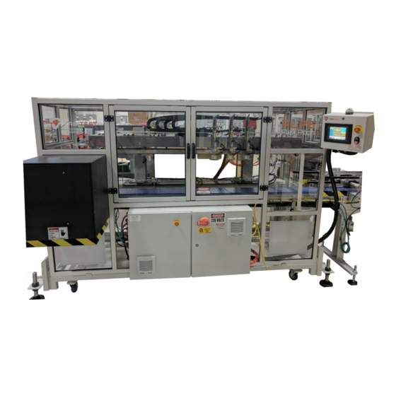
Page 8: Alps Flex Pitch Multi-Moving Head Leak Tester
Flex Pitch has a smaller footprint to perform leak testing on an existing conveyor line, requiring no conveyor line modifications. The Flex Pitch has built in flexibility with 2-4 test heads for a variety of container sizes up to 350oz. -
Page 9: Linear Dimensions Of The Flex Pitch Machine
AIR LOGIC POWER SYSTEMS (ALPS) Flex Pitch GENERAL INFORMATION Linear Dimensions of the Flex Pitch machine FLEX PITCH INSTALLATION MANUAL TM 2017-014 REV01 © 8/2/2017... -
Page 10: Section 1: Location Site And Installation Requirements
AIR LOGIC POWER SYSTEMS (ALPS) Flex Pitch INSTALLATION SITE Section 1: Location Site and Installation Requirements Location It is recommended that you: 1. Position the machine on a stable, flat surface. 2. Locate in a cooler area where the containers will remain at a lower temperature where the probe seal will not stick. -
Page 11: Section 2: Components Inventory
AIR LOGIC POWER SYSTEMS (ALPS) Flex Pitch COMPONENTS INVENTORY Section 2: Components Inventory A standardized inventory of normal components shipped and installed with standard Flex Pitch machines (2 listings). Verify that all components are present on-site. STANDARD COMPONENTS DESCRIPTION (With devices installed) -
Page 12: Common Components Shipped With The Flex Pitch
The following pages show a series of photos of commonly boxed and assembled components that should come with a typical crated Flex Pitch shipment. Tunnel Shielding: These come as a set, unboxed with the shipment. Two hardware bags contained within come with this installation. -
Page 13: Common Components
AIR LOGIC POWER SYSTEMS (ALPS) Flex Pitch COMPONENTS INVENTORY Common Components Photo-Eyes and Photo-Eye brackets Shown here is the pre-assembled photo-eye emitter reflector. See section 4 for installation and positioning. This photo-eye is the downstream jam photo-eye just after the exit. -
Page 14: Section 3: Installation To Conveyor System
AIR LOGIC POWER SYSTEMS (ALPS) Flex Pitch INSTALLATION to CONVEYOR Section 3: Installation to Conveyor System WARNING! MACHINE MUST BE HOISTED FROM THE BACK AS SHOWN BELOW. SPREAD FORKS APART! THIS MACHINE HAS A HIGH CENTER OF GRAVITY. FORKS MUST SUPPORT THE ENTIRE GIRTH OF THIS MACHINE. - Page 15 Installation to Conveyor System 3. Hoist the Flex Pitch machine from the pallet and install legs: There are four brackets securing the Flex Pitch machine at each corner of the pallet. Dispose of the brackets. a. Unbolt the Flex Pitch machine from the pallet base.
- Page 16 With the Flex Pitch unit suspended in the air, install all four legs. a. Adjust leveling feet-do not tighten yet. b. Lower the Flex Pitch to the floor (supported by the leveling feet) and check adjustments with a level. Raise the unit again as needed to make further adjustments as needed.
- Page 17 8. Front Panel Assembly: Unfasten these screws and remove the entire panel assembly as shown in the photos below. Use a 5mm Allen wrench. Left: Left side of Flex Pitch Middle: Top Middle of Flex Pitch Right: Right side of Flex Pitch FLEX PITCH INSTALLATION MANUAL...
- Page 18 AIR LOGIC POWER SYSTEMS (ALPS) Flex Pitch INSTALLATION to CONVEYOR Installation to Conveyor System Enlist the aid of another person to complete this step. FLEX PITCH INSTALLATION MANUAL TM 2017-014 REV01 © 8/2/2017...
- Page 19 Installation to Conveyor System 9. Positioning the machine: With the machine lowered onto its set of wheels (or by using a forktruck), gently move the Flex Pitch machine to the conveyor system. The machine must be positioned perfectly parallel with the conveyor.
- Page 20 AIR LOGIC POWER SYSTEMS (ALPS) Flex Pitch INSTALLATION to CONVEYOR Installation to Conveyor System 10. Centering the probes over the conveyor: This assures that the machine is parallel to the conveyor. Ease the machine into position with the probes centered over the center of the conveyor. Lock and immobilize all casters.
- Page 21 AIR LOGIC POWER SYSTEMS (ALPS) Flex Pitch INSTALLATION to CONVEYOR Installation to the Conveyor System 11. Leveling the machine: Vertical and Tilt Alignment Use a standard bar-type level to fine-tune the height adjustment: Tilt Adjustment: First, do so the TILT, with the level placed vertically as shown (left).
- Page 22 AIR LOGIC POWER SYSTEMS (ALPS) Flex Pitch INSTALLATION to CONVEYOR Installation to the Conveyor System Note: Before proceeding, recheck and verify that the probes are vertically centered over the conveyor belt. Once this is done, continue with the setup process. Machine must be parallel to the...
- Page 23 AIR LOGIC POWER SYSTEMS (ALPS) Flex Pitch INSTALLATION to CONVEYOR Installation to the Conveyor System 12. Install the front panel assembly-outside fasteners: Enlist the aid of another person to handle and secure the front panel. All screws will require a 5mm Allen wrench.
-
Page 24: Vertical Adjustment For Probe Carriage
AIR LOGIC POWER SYSTEMS (ALPS) Flex Pitch INSTALLATION to CONVEYOR Vertical Adjustment for Probe Carriage 14. Below: Manual clamps used to lock/unlock the probe carriage into position. Left Side: Rotate the lever clockwise to loosen, counter-clockwise to tighten. Right Side: Rotate the lever clockwise to tighten and counter-clockwise to loosen. - Page 25 AIR LOGIC POWER SYSTEMS (ALPS) Flex Pitch INSTALLATION to CONVEYOR Installation to Conveyor System 16. Fine-tune the height adjustment: Refer to the vertical scale at the right end, graduated in millimeters (mm). The clamping device has a built-in indicator that denotes the actual height setting. This height setting shows 191mm.
-
Page 26: Section 4: Installing Peripheral Devices
Photo-Eyes and support brackets 1. Photo-Eyes and Photo-Eye brackets The ALPS Flex Pitch comes with (1) photo-eye sensor/emitter and (1) reflectors mounted in a bracket assembly (shown below) for the optional Downstream Jam photoeye. Mounting screws: Use an M8 Allen wrench. Hex nuts: Use an M17 Open-end wrench. Vertically adjust emitters and reflectors with an M5 Allen wrench. -
Page 27: Photo-Eyes: Mounting And Positioning On Conveyor
3. Photo-Eyes: Mounting and Positioning on Conveyor Note: Optimal mounting and placement of photo eyes may require containers running through the Flex Pitch at production speeds. Other factors that enter into deciding any permanent location before drilling mounting holes into the side panel of the conveyor are: exact location, which depends on floor space, conveyor configuration and proximity to any blow molder machinery, and rate of speed of the conveyor. -
Page 28: Change Mode Button Options
AIR LOGIC POWER SYSTEMS (ALPS) Flex Pitch INSTALLING PERIPHERAL DEVICES Change Mode Button Options. Teach, Light-On, Dark-On, and Delay modes are different functions of the sensor. Teach Mode: A means of adjustment. Dark-On Mode: This means that the sensor does not detect its reflected signal. As a result, the sensor is programmed to activate and relay instructions to the PLC. - Page 29 AIR LOGIC POWER SYSTEMS (ALPS) Flex Pitch INSTALLING PERIPHERAL DEVICES FLEX PITCH INSTALLATION MANUAL TM 2017-014 REV01 © 8/2/2017...
-
Page 30: Installing The Encoder To The Conveyor
AIR LOGIC POWER SYSTEMS (ALPS) Flex Pitch INSTALLING PERIPHERAL DEVICES Installing the Encoder to the Conveyor Mount the encoder to the conveyor, using the providing mounting hardware, so that the Encoder wheel is resting on the conveyor. Screw in the M12 connector cable from the FlexPitch to the Encoder wheel. -
Page 31: Installing Intake Tunnel Guard
AIR LOGIC POWER SYSTEMS (ALPS) Flex Pitch INSTALLING PERIPHERAL DEVICES Installing Intake Tunnel Guard There is adequate hardware to install both intake and exit guards. The hardware is shipped preinstalled on the tunnel guards. Unscrew the brackets from the tunnel guard, mount the anchors to the 80/20 and refasten the bolts. -
Page 32: Install Exit Tunnel Guard
AIR LOGIC POWER SYSTEMS (ALPS) Flex Pitch INSTALLING PERIPHERAL DEVICES Install Exit Tunnel Guard Unscrew the brackets from the tunnel guard, mount the anchors to the 80/20 and refasten the bolts. Left: Brackets mounted to frame Right: Tunnel guard mounted to frame FLEX PITCH INSTALLATION MANUAL TM 2017-014 REV01 ©... -
Page 33: Section 5: Power Up
AIR LOGIC POWER SYSTEMS (ALPS) Flex Pitch POWER UP Section 5: Power up Main Electrical Power Switch The main power switch is located on the side of the high-voltage enclosure. Top: Turn clockwise to turn ON. Turn counter-clockwise to turn OFF. Bottom: Electrical power in LOCKOUT. -
Page 34: Airflow Control
AIR LOGIC POWER SYSTEMS (ALPS) Flex Pitch POWER UP Airflow Control Airflow is controlled at the air intake (left). Airflow is regulated at the outflow regulator (right). Outflow Regulator Adjustment Ring Left: Main air intake open; Right: Air intake closed Air intake pressure gauge Verify that the air pressure on the gauge (right) is set to at least 80 psi.
Need help?
Do you have a question about the FLEX PITCH and is the answer not in the manual?
Questions and answers