Table of Contents
Advertisement
Quick Links
Air Logic Power Systems, LLC
th
1745 S. 38
Street, Suite 100
Milwaukee, WI. 53215-1732
Phone: 414-671-3332 Fax: 414-671-6645
24 Hour Service Hotline: 800-325-8717
www.alpsleak.com and info@alpsleak.com
ALPS SPEEDGLIDER LEAK
TESTER FIELD
INSTALLATION MANUAL
STANDARD SPEEDGLIDER INSTALLATION MANUAL
i
TM 2012-014 REV00 © 8/6/2012
Advertisement
Table of Contents

Related Manuals for Alps Electric SPEEDGLIDER


Summary of Contents for Alps Electric SPEEDGLIDER
- Page 1 Air Logic Power Systems, LLC 1745 S. 38 Street, Suite 100 Milwaukee, WI. 53215-1732 Phone: 414-671-3332 Fax: 414-671-6645 24 Hour Service Hotline: 800-325-8717 www.alpsleak.com and info@alpsleak.com ALPS SPEEDGLIDER LEAK TESTER FIELD INSTALLATION MANUAL STANDARD SPEEDGLIDER INSTALLATION MANUAL TM 2012-014 REV00 © 8/6/2012...
-
Page 3: System Modifications
Air Logic Power Systems LLC. Software Installation of any new or modification of existing software in the SPEEDGLIDER not approved by Air Logic Power Systems LLC may affect the operation or performance of the machine and possibly void the warranty and or service agreements. -
Page 4: Table Of Contents
Section 2: Components Inventory Common Components shipped with the SPEEDGLIDER..................5 Section 3: Installation to Conveyor System 7 Hoist the SPEEDGLIDER machine from the pallet and install legs ..............7 Install Support Legs ...............................8 Transport the SPEEDGLIDER ..........................8 Installation to Conveyor System procedure ......................9 Front Panel Assembly ............................ - Page 5 Rail Setup & Adjustment ............................ 34 Section 6: System Power-Up Main Electrical Power Switch ..........................35 Electrical Power Lockout/Tag Out ........................35 Airflow Control ..............................36 Air intake pressure gauge ..........................36 Pneumatic Lockout/Tag Out ..........................36 SPEEDGLIDER INSTALLATION MANUAL TM 2012-014 REV00 © 8/6/2012...
-
Page 7: General Information
General Information Introduction This manual is a guide on how to install the ALPS SpeedGlider Linear Leak Tester. A complementary listing of the standard components shipped with the unit is also provided. Warnings, Cautions, and Notes: Note: Notation messages provide additional information or helpful tips about a topic. -
Page 8: Linear Dimensions
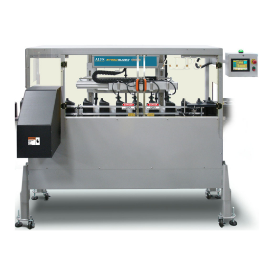
250 CPM (15,000 CPH). The SpeedGlider 4.5 shown here is a four-station machine designed for containers ranging from approximately 8 to 64 ounces (250ml to 2L); with container dimensions nominally up to 5” x 5” x 14” (127 x 127 x 355mm) tall. - Page 9 AIR LOGIC POWER SYSTEMS (ALPS) GENERAL INFORMATION Linear Dimensions of the SpeedGlider machine SPEEDGLIDER INSTALLATION MANUAL TM 2012-014 REV00 © 8/6/2012...
-
Page 11: Section 1 Location, Installation, & Site Requirements
OR OTHER FOREIGN MATTER. Plug in air hose here Adjustment knob Primary Coalescing Reject Air Incoming Air Particulate Air Filter Regulator Regulator and Filter Pressure Gauge Conventional air regulator and filtration system SPEEDGLIDER INSTALLATION MANUAL TM 2012-014 REV00 © 8/6/2012... -
Page 12: Section 2: Components Inventory
Section 2: Components Inventory A standardized inventory of normal components shipped and installed with standard and field rotary SPEEDGLIDER machines (2 listings). Verify that all components are present on-site. STANDARD COMPONENTS DESCRIPTION (With tooling and devices installed) SpeedGlider Set of (2) Plexiglass guards for entry and exit point of... -
Page 13: Common Components Shipped With The Speedglider
The following pages show a series of photos of commonly boxed and assembled components that should come with a typical crated SpeedGlider shipment. Tunnel Shielding: These come as a set, unboxed with the shipment. A single hardware bag contained within and marked “J10751 Tunnel Hardware”... -
Page 14: Photo-Eyes And Photo-Eye Brackets
Rail kit comes with a set of (6) 6mm screws and lock nuts to attach to conveyor directly opposite the timing screw. Rail kit to be attached to conveyor: Rail is same length as timing screw. SPEEDGLIDER INSTALLATION MANUAL TM 2012-014 REV00 © 8/6/2012... - Page 15 MACHINE. DAMAGE CAN OCCUR IF MACHINE IS NOT FULLY SUPPORTED FRONT AND BACK. Steps: 1. Hoist the SpeedGlider machine from the pallet and install legs There are four brackets securing the SpeedGlider machine at each corner of the pallet. Dispose of the brackets. a. Unbolt the SpeedGlider machine from the pallet base.
- Page 16 With the SpeedGlider unit suspended in the air, install all four legs. a. Adjust leveling feet-do not tighten yet. b. Lower the SpeedGlider to the floor (supported by the leveling feet) and check adjustments with a level. Raise the unit again as needed to make further adjustments as needed.
- Page 17 6. Inside. With a 5mm Allen wrench, remove the following screws that secure the lower portion of the front panel. Inside the machine; remove these groups of fasteners. Use a 5mm Allen wrench. SPEEDGLIDER INSTALLATION MANUAL TM 2012-014 REV00 © 8/6/2012...
- Page 18 Use an M5 Allen wrench. Remove this piece of plexiglass. 8. Plexiglass End-caps. Remove these two screws; one at each end. It is not necessary to remove the plexiglass panels themselves. Use a 5mm Allen wrench. SPEEDGLIDER INSTALLATION MANUAL TM 2012-014 REV00 © 8/6/2012...
- Page 19 9. Front Panel Assembly: Unfasten these screws and remove the entire panel assembly as shown in the diagram below. Open doors to access screws behind. Use a 5mm Allen wrench. Enlist the aid of another person to complete this step. Use an M5 Allen wrench to loosen. SPEEDGLIDER INSTALLATION MANUAL TM 2012-014 REV00 © 8/6/2012...
- Page 20 SECTION 3 INSTALLATION to CONVEYOR Installation to Conveyor System Left: This is the SpeedGlider machine with the front guard removed. At this time, move the unit to its final position along the conveyor. 10. Positioning the machine: With the machine lowered onto its set of wheels, gently move the SpeedGlider machine to the conveyor system.
- Page 21 This assures that the machine is parallel to the conveyor. Ease the machine into position with the probes centered over the center of the conveyor. Lock and immobilize all casters. Raise the machine onto the adjustable feet. The machine has assumed its permanent position to the conveyor. SPEEDGLIDER INSTALLATION MANUAL TM 2012-014 REV00 © 8/6/2012...
- Page 22 When using small root (38 mm diameter) timing screws make sure the “Height Indicator’ is offset 20 mm below conveyor service. Viewed from the rear of the machine: Height indicator tab at both corners. SPEEDGLIDER INSTALLATION MANUAL TM 2012-014 REV00 © 8/6/2012...
- Page 23 AIR LOGIC POWER SYSTEMS (ALPS) SECTION 3 INSTALLATION to CONVEYOR SPEEDGLIDER INSTALLATION MANUAL TM 2012-014 REV00 © 8/6/2012...
- Page 24 Left: Adjust for tilt. Right: Adjust for height at each end to the level of the conveyor. Adjustable Foot Note: Minor corrections can Use a 1-1/8 Open- be made at this point by End Wrench making small adjustments at each foot. SPEEDGLIDER INSTALLATION MANUAL TM 2012-014 REV00 © 8/6/2012...
- Page 25 Machine must be parallel to the conveyor! 15. With vertical alignment established, adjust the brackets and fasten each bracket to the conveyor. Use a 5mm Allen wrench. 16. Install end panels. Use a 5mm open-end wrench. SPEEDGLIDER INSTALLATION MANUAL TM 2012-014 REV00 © 8/6/2012...
- Page 26 18. Inside Fasteners. With a 5mm Allen wrench, remove the following screws that secure the lower portion of the front panel. Inside the machine; remove these groups of fasteners. Use a 5mm Allen wrench. SPEEDGLIDER INSTALLATION MANUAL TM 2012-014 REV00 © 8/6/2012...
- Page 27 Left: Jokab door sensors. Right: Reject Verification sensor. Secure all cables with tape to inside surfaces. 20. Front Plexiglass Panel. At the upper left corner of the machine, reattach this piece of Plexiglass. It is secured by (3) screws. Use a 5mm Allen wrench. SPEEDGLIDER INSTALLATION MANUAL TM 2012-014 REV00 © 8/6/2012...
- Page 28 Mount rail kit to conveyor directly opposite the timing screw. Railing is installed directly opposite the timing screw and is the same length as the timing screw. Attach with 5mm Allen wrench. Vertically adjustment varies with the size of the container. SPEEDGLIDER INSTALLATION MANUAL TM 2012-014 REV00 © 8/6/2012...
- Page 29 Left: clockwise to loosen, counter-clockwise to tighten. Right end; counter-clockwise to loosen, clockwise to tighten. 24. Raise the probe carriage assembly by turning the worm-gear crank as shown. Turn clockwise to raise, and counter-clockwise to lower. SPEEDGLIDER INSTALLATION MANUAL TM 2012-014 REV00 © 8/6/2012...
- Page 30 26. With a single container in position on the conveyor, raise the probe carriage to a level just ¼ inch above the top of the container that is going to be run. With the temporary vertical setting established, remove the container. Installation is complete. ¼ Inch clearance SPEEDGLIDER INSTALLATION MANUAL TM 2012-014 REV00 © 8/6/2012...
- Page 31 Installing the timing screw Shown is a step-by-step procedure for how the timing screw is installed. This is normally performed after the SpeedGlider has been mated to the host conveyor system. View of SpeedGlider shown without conveyor or front guard installed.
- Page 32 (C to C)-which means “center to center”. This inscription is found at the drive motor end of the screw. Scaled height setting for timing screw Scaled horizontal center setting for timing screw Timing screw with manufacturer's specifications molded into the surface. SPEEDGLIDER INSTALLATION MANUAL TM 2012-014 REV00 © 8/6/2012...
- Page 33 Note that due the weight of the drive motor; vertical adjustment knobs will be harder to turn. Bottom: The scales are graduated in millimeters. Adjust to the desired height and tighten both wheels. SPEEDGLIDER INSTALLATION MANUAL TM 2012-014 REV00 © 8/6/2012...
- Page 34 With a container positioned in a pocket in the timing screw, make the adjustment. There should be a 1/16” gap between the container and the railing. Timing Screw: Forward/Backward settings: Left: Drive motor end. Right: Screw coupling end. SPEEDGLIDER INSTALLATION MANUAL TM 2012-014 REV00 © 8/6/2012...
-
Page 35: Photo-Eyes: Placement And Positioning
Photo-Eyes and support brackets 1. Photo-Eyes and Photo-Eye brackets The ALPS SPEEDGLIDER comes with (4) photo-eye sensor/emitters and (4) reflectors mounted in a bracket assembly (shown below). The fourth photo-eye/reflector is an optional (fast speed photo-eye). Mounting screws: Use an M8 Allen wrench. Hex nuts: Use an M17 Open-end wrench. Vertically adjust emitters and reflectors with an M5 Allen wrench. -
Page 36: Normal/Start Photo-Eye
The positioning of the slow/stop photo-eye can be anywhere from 3-8 feet away, upstream from the timing screw. This placement depends on the SpeedGlider speed and containers per min/sec. The optional placement result is when the SpeedGlider comes to a normal controlled stop and the timing screw is still full of containers. -
Page 37: Tuning Photo-Eyes
AIR LOGIC POWER SYSTEMS (ALPS) SECTION 6 CONVEYOR RAILING Tuning Photo-Eyes OPTEX DR-Q150TCN Sensor tuning and adjustment Change Mode: Press and hold down the Change Mode button until the LED begins to flash. You are now program mode. It is at this time that sensitivity can be adjusted. -
Page 38: Change Mode Button Options
AIR LOGIC POWER SYSTEMS (ALPS) SECTION 6 CONVEYOR RAILING Change Mode Button Options Light-On Mode: This means that the sensor detects its reflected signal. Sensor relays output instructions to the PLC. Delay Mode: Detects signal and delays pulse to the PLC. Shown here are the various mode options, LED screen. - Page 39 AIR LOGIC POWER SYSTEMS (ALPS) SECTION 6 CONVEYOR RAILING Installing Peripheral Devices 3. Installing Intake and Exit Tunnel Guards There is adequate hardware to install both intake and exit guards. Hardware Fasteners for Tunnel Guards: (8) Allen Screws (8) Nylon Hex nuts Intake end: Uninstalled.
-
Page 40: Install Exit Tunnel Guards
AIR LOGIC POWER SYSTEMS (ALPS) SECTION 6 CONVEYOR RAILING Installing Peripheral Devices 4. Install Exit Tunnel Guards The photo below shows the correct configuration for support fasteners as they appear on the frame. Assemble the exit tunnel guard as shown. Left: Correct configuration for brackets. -
Page 41: Install Pressure Gauge
AIR LOGIC POWER SYSTEMS (ALPS) SECTION 6 CONVEYOR RAILING Installing Peripheral Devices Pressure Gauge 5. Install Pressure Gauge Remove plug from indicated regulator and install the pressure gauge. Wrap the gauge stem with several windings of Teflon tape before installing. Make sure the gauge reads right-side up. Plug in air hose here Adjustment... -
Page 42: Section 5: Conveyor Railing
Section 5: Conveyor Railing Rail Setup and Adjustment Shown below is the optimum setup for guide rails with the ALPS SPEEDGLIDER. Railing should not exceed the length of the timing screw. Horizontal adjustment of the rails is controlled by the individual manual clamping devices on each mounting bracket. -
Page 43: Section 6: System Power-Up
The main power switch is located on the side of the high-voltage enclosure. Top: Turn clockwise to turn ON. Turn counter-clockwise to turn OFF. Bottom: Electrical power in LOCKOUT. Turn counter-clockwise to the OFF position for LOCK-OUT/TAG-OUT. SPEEDGLIDER INSTALLATION MANUAL TM 2012-014 REV00 © 8/6/2012... -
Page 44: Airflow Control
Verify that the air pressure on the gauge (right) is set to between 80 psi. Turn the adjustment ring to vary the outgoing air pressure. Lockout-Tag Out Lock airflow in the OFF position when the machine is down for maintenance. SPEEDGLIDER INSTALLATION MANUAL TM 2012-014 REV00 © 8/6/2012...
Need help?
Do you have a question about the SPEEDGLIDER and is the answer not in the manual?
Questions and answers