
Related Manuals for LEAB LPS Series


Summary of Contents for LEAB LPS Series
- Page 1 1212, 1512, 2512 Lithium Power Supply User Manual LEAB Automotive GmbH User Manual Thorshammer 6 Version: V3.1 DE-24866 Busdorf Issue date: 16.04.2019...
-
Page 2: Table Of Contents
Installation instructions About this Manual Table of Contents About this Manual .................. 1 General Safety ..................2 Technical Specifications ................3 Unpacking the LPS ................... 5 About the LPS ..................5 Package Contents ..................7 Display ..................... 8 Installing the Connection Set / Preparing Connections ......9 Mounting .................... -
Page 3: General Safety
Installation instructions General Safety Signal word Meaning Warns of imminent danger resulting in death or serious DANGER injury. Warns of a potentially dangerous situation that can WARNING result in death or serious injury. Warns of a potentially dangerous situation that can CAUTION result in moderate or minor injuries. -
Page 4: Technical Specifications
Installation instructions Technical Specifications Any modifications to the device or its components are prohibited and do not conform to its intended use. The LPS is a protection class 1 device. Only connect the LPS to low-voltage sources which have an earth connection (shockproof socket with PE) and a RCD circuit breaker (FI). - Page 5 Installation instructions Technical Specifications Model LPS 1212 LPS 1512 LPS 2512 Part number 014-02001GF 014-01004GF 014-03001GF AC output Voltage / frequency (rated 230 V / 50 Hz values) Power (continuously) 1000 W 1300 W 2000 W Power (mains priority circuit) 1800 W 1800 W 2300 W...
-
Page 6: Unpacking The Lps
Installation instructions Unpacking the LPS Unpacking the LPS To unpack the device, perform the following steps: Lift the device out of the transport box using the black carrying handles on the front and back. The device is unpacked. After unpacking, check the scope of delivery of the LPS (see page 7). About the LPS Number Details... - Page 7 Installation instructions About the LPS Number Details Carrying handle (back) D-Sub plug for communications connections AC output (230 V) Neutrik, grey AC input (230 V), Neutrik, blue DC output, (12 V) Anderson, red DC input, (12 V) Anderson, grey Page 6 of 25...
-
Page 8: Package Contents
Installation instructions Package Contents Package Contents Figure Part Name Lithium Power Supply (LPS) D-Sub data adapter Anderson plug SB50, red Anderson plug SB50, grey Contacts for Anderson SB50 plugs 4 x M3 screws for fastening the Anderson plugs Neutrik PowerCon type A plug, blue Neutrik PowerCon type B plug, grey Mains cable, Neutrik PowerCon type A with two-pin earthed plug... -
Page 9: Display
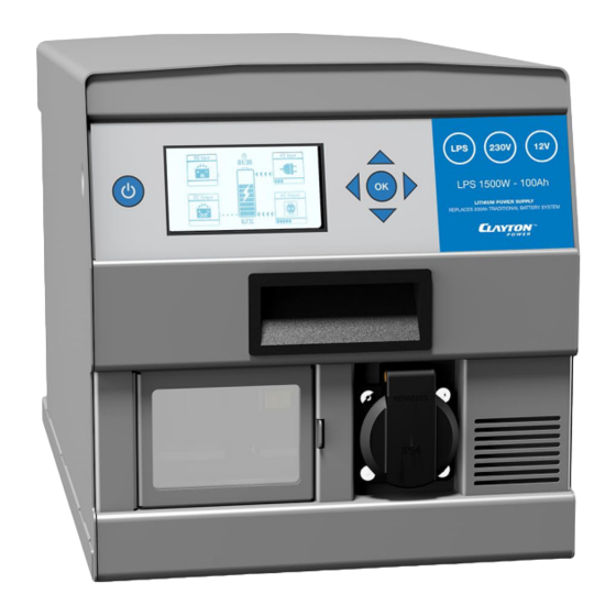
Installation instructions Display Display Number Item On/Off button Display Arrow button OK button Item DC input (12 V) Shows the charging capacity in 10 % increments Shows the direction of the current flow Shows the remaining operation (-hh:mm) or charging time (hh:mm) AC input (230 V) Shows the discharging capacity in 10 % increments AC output (230 V) -
Page 10: Installing The Connection Set / Preparing Connections
Installation instructions Installing the Connection Set / Preparing Connections Installing the Connection Set / Preparing Connections Anderson Plug To mount the Anderson plug, observe the following notes: For installation you need a H07V-K or equivalent electrical cable with a cross-section of 16 mm² and a crimping tool. Grey Anderson plug for DC input (12 V). -
Page 11: Mounting
Installation instructions Mounting Mounting the D-Sub Data Adapter To mount the D-Sub data adapter, observe the following instructions: You need an H07V-K or equivalent electrical cable with a cross-section of 1 mm² and, if necessary, a fuse holder. Item Single wire Data transmission CAN-Low Software update... -
Page 12: Installation
Installation instructions Installation 10 Installation Ensure that the LPS is switched off during installation. Connecting the AC Input (230 V) To install the device to the 230-V mains, perform the following steps: Insert the blue Neutrik plug of the mains cable into the AC input (230 V) on the device. - Page 13 Installation instructions Installation Secure the signal cable near the connection to the vehicle with a suitable fuse (1 A ... 3 A). Connect the open end of the signal cable to pin 9 of the D-Sub data adapter. Connect the D-Sub data adapter to the D-Sub plug on the device. Plug the grey Anderson plug into the DC input (12 V) on the device and screw it tight.
-
Page 14: Installation Of Accessories
Installation instructions Installation of Accessories 11 Installation of Accessories Connecting Solar Panel To charge the LPS with solar panels, perform the following steps: You need a solar charge controller with Maximum Power Point Tracking (MPPT) and an output voltage (DC) of 14.5 V ... 15 V. - Page 15 Installation instructions Installation of Accessories Connecting the CDR Power Distributor Relay The LPS has a jumpstart function to start the vehicle when the starter battery is discharged. In an emergency, the CDR power distributor relay ensures controlled and current-limited charge compensation between the LPS and the empty starter battery.
-
Page 16: Operation
Connecting the LPS Remote Display If the LPS is installed such that the display is not visible, an LPS remote display from LEAB can be connected to control the LPS. To install the remote display, follow the notes and instructions in the manual. - Page 17 Installation instructions Operation Limiting Input Current (230 V, AC) The LPS gives you the option to control the input current of the AC input, adjustable values are between 1 A and 10 A. To limit the input current at the AC input, perform the following steps: Device is ready for operation.
- Page 18 Installation instructions Operation Deactivate/Activate Energy Saver (230 V, DC) The Energy Saver is used to set a threshold and a time. If the value falls below this threshold, the set time runs down and the AC output (230 V) is automatically deactivated after the time has elapsed.
- Page 19 Installation instructions Operation Activate/Deactivate 12-V Output To activated or deactivate the 12-V output, perform the following steps: Device is ready for operation. Press the On/Off button to open the On/Off menu. Select the menu item 'DC Out' by pressing the arrow buttons (up/down). DC output is active DC output is inactive To change the setting, press the OK button.
- Page 20 Installation instructions Operation Deactivate/Activate Shutdown Delay (12 V, DC) With the shutdown delay you have the option to delay the deactivation of the DC output until after switching off the LPS. To activate or deactivate the shutdown delay, perform the following steps: The device is switched on.
-
Page 21: Displays
Installation instructions Displays 13 Displays 230 VAC Output Operation Status Power Voltage Current Energy Saver (No load) Energy Saver (Threshold) 230 VAC Charging Operation Status Power Voltage Current Maximum Current 12 VDC Output ... -
Page 22: Maintenance
Installation instructions Maintenance General Battery Status Operation Status Remaining Operation Current Capacity Power Voltage Current Temperature Cell 1, 2, 3, 4 Number of Cycles Temperature Transformer Temperature IGBT Module ... -
Page 23: Troubleshooting
Installation instructions Troubleshooting 15 Troubleshooting Replacing Fuses (DC) If a fuse is tripped, there is no current flow on the DC side. A total of 6 vehicle fuses (40 A) are located on the rear of the LPS. The upper 3 fuses protect the DC output, the lower 3 fuses the DC input. - Page 24 Installation instructions Troubleshooting Error Error Description Solution Code E020, Error in inverter Perform a restart. If the error has not been E021 corrected, contact your dealer to arrange a service. E022 Error in charger Perform a restart. If the error has not been corrected, contact your dealer to arrange a service.
- Page 25 Installation instructions Troubleshooting Error Error Description Solution Code E102 Current measurement Contact your dealer to arrange a service. error (DC) E103 Start error in power Perform a restart. If the error has not been supply unit corrected, contact your dealer to arrange a service.
-
Page 26: Disassembly
Installation instructions Disassembly 16 Disassembly To dismantle the LPS, perform the following steps: Press the On/Off button to open the On/Off menu. Press the OK button to confirm the 'Shutdown' menu item and switch off the LPS. Disconnect the two-pin earthed plug, Neutrik and Anderson connectors as well as the D-Sub data adapter from the LPS. - Page 28 LEAB Automotive GmbH Thorshammer 6 DE-24866 Busdorf Germany Tel.: +49(0) 4621 9 78 60-0 Fax: +49(0) 4621 9 78 60-260 Email: anfrage@leab.eu Web: www.leab.eu...
Need help?
Do you have a question about the LPS Series and is the answer not in the manual?
Questions and answers
How do you charge the LPS Model no LPS 2512
To charge the LEAB LPS 2512, follow these steps:
1. Ensure the LPS is switched off during installation.
2. Insert the blue Neutrik plug of the mains cable into the AC input (230 V) on the device.
3. Turn the Neutrik plug clockwise until it clicks into place.
4. Plug the two-pin earthed plug into a 230-V mains supply.
The LPS will automatically start the charging process.
This answer is automatically generated
What is Error code 121