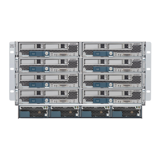
Cisco UCS 5108 Installation Manual
Server chassis
Hide thumbs
Also See for UCS 5108:
- Spec sheet (50 pages) ,
- Installation manual (114 pages) ,
- Manual (8 pages)
Table of Contents
Advertisement
Quick Links
Cisco Ucs 5108 Server Chassis Installation Guide
First Published: 2009-06-10
Last Modified: 2019-11-25
Americas Headquarters
Cisco Systems, Inc.
170 West Tasman Drive
San Jose, CA 95134-1706
USA
http://www.cisco.com
Tel: 408 526-4000
800 553-NETS (6387)
Fax: 408 527-0883
Advertisement
Table of Contents

Related Manuals for Cisco UCS 5108


Summary of Contents for Cisco UCS 5108
- Page 1 Cisco UCS 5108 Server Chassis Installation Guide First Published: 2009-06-10 Last Modified: 2019-11-25 Americas Headquarters Cisco Systems, Inc. 170 West Tasman Drive San Jose, CA 95134-1706 http://www.cisco.com Tel: 408 526-4000 800 553-NETS (6387) Fax: 408 527-0883...
- Page 2 Cisco has more than 200 offices worldwide. Addresses and phone numbers are listed on the Cisco website at www.cisco.com/go/offices. Cisco and the Cisco logo are trademarks or registered trademarks of Cisco and/or its affiliates in the U.S. and other countries. To view a list of Cisco trademarks, go to this URL: www.cisco.com...
-
Page 3: System Overview
The Cisco UCS 5108 Server Chassis and its components are part of the Cisco Unified Computing System (UCS), which uses the Cisco UCS 5108 server system with the two I/O modules and the Cisco UCS Fabric Interconnects to provide advanced options and capabilities in server and data management. All servers are managed via the GUI or CLI with Cisco UCS Manager. - Page 4 • UCS C-Series rack servers, including the following: • Cisco UCS C240 M4 or C240 M5 rack servers and Cisco UCS C220 M4 or C220 M5 rack servers—Up to seven rack servers, either C240 or C220, or a combination of the two.
- Page 5 This simplicity eliminates the need for dedicated chassis management and blade switches, reduces cabling, and enables the Cisco Unified Computing System to scale to 40 chassis without adding complexity. The Cisco UCS 5108 server chassis is a critical component in delivering the Cisco Unified Computing System benefits of data center simplicity and IT responsiveness.
- Page 6 The chassis is six rack units (6 RU) high and can mount in an industry-standard 19-inch rack with square holes (such as the Cisco R Series Racks) or in round hole racks when an adapter is used. The chassis can house up to eight half-width Cisco UCS B-Series Blade Servers and can accommodate both half- and full-width blade form factors.
- Page 7 • 10 G Base-KR The midplane is an entirely passive device. Blade Servers The Cisco UCS B-Series Blade Servers are based on industry-standard server technologies and provide the following: • Up to two or four Intel multi-core processors, depending on the server •...
- Page 8 • Out-of-band access by remote KVM, Secure Shell (SSH), and virtual media (vMedia) as well as Intelligent Platform Management Interface (IPMI) The Cisco UCS B-Series offers multiple blade server models. The supported processor family is indicated by M4 or M5 designations on the model.
- Page 9 For full service and installation instructions, see the Cisco UCS B480 M5 Blade Server Installation and Service Note. Up to four Cisco UCS B480 M5 Blade Servers can be installed in the Cisco UCS 5108 chassis. Figure 3: Cisco UCS B480 M5 Blade Server Front Panel...
- Page 10 For full service and installation instructions, see the Cisco UCS B260 M4 and B460 M4 Scalable Blade Server Installation and Service Note. Up to two Cisco UCS B460 M4 Blade Servers can be installed in the Cisco UCS 5108 chassis. Cisco UCS 5108 Server Chassis Installation Guide...
- Page 11 Cisco UCS B260 M4 and B460 M4 Scalable Blade Server Installation and Service Note. You can install up to four UCS B260 M4 Blade Servers in the Cisco UCS 5108 server chassis. Figure 6: Cisco UCS B260 M4 Scalable Blade Server...
- Page 12 I/O module in the chassis. Cards are released on an ongoing basis. Cisco UCS 6324 Fabric Interconnect For UCS Mini Chassis The Cisco UCS 6324 Fabric Interconnect (UCS-FI-M-6324) is an integrated fabric interconnect and I/O module. It can be configured only with the UCS Mini versions of the chassis (UCSB-5108-AC2 and UCSB-5108-DC2 ).
- Page 13 32 10-Gigabit backplane ports to support up to 8 half-width blade servers in the chassis. It can be hot-plugged into the rear of a Cisco UCS 5108 blade server chassis. A maximum of two UCS 2408 IOMs can be installed in a chassis.
- Page 14 • The UCS 2408 IOM requires Cisco UCS Manager 4.0(4c) or later software. The Cisco UCS 2408 IOM provides chassis management control and blade management control, including control of the chassis, fan trays, power supply units, and blades. It also multiplexes and forwards all traffic from the blade servers in the chassis to the 10/25-Gigabit Ethernet uplink network ports that connect to the fabric Interconnect.
- Page 15 There are no buttons on the IOM. Connectors There are 8 10/25-Gigabit SFP28 uplink ports on the front of the IOM. The HDMI connector uses a special Y-dongle cable that includes Ethernet management and serial console connectors. Cisco UCS 5108 Server Chassis Installation Guide...
- Page 16 The Cisco UCS 2304 IOM (Fabric Extender) is an I/O module with 8 40-Gigabit backplane ports and 4 40-Gigabit uplink ports. It can be hot-plugged into the rear of a Cisco UCS 5108 blade server chassis. A maximum of two UCS 2304 IOMs can be installed in a chassis.
- Page 17 HDMI console connector and Captive screws for the insertion latches Ethernet management port 40-Gigabit uplink ports Insertions latches 40-Gigabit backplane ports LEDs The front of the IOM has a system status LED and port activity LEDs. Cisco UCS 5108 Server Chassis Installation Guide...
- Page 18 LEDs There is one LED indication of the fan module’s operational state. See Interpreting LEDs, on page 22 details. Buttons and Connectors No buttons or connectors are on a fan module. Cisco UCS 5108 Server Chassis Installation Guide...
-
Page 19: Power Supplies
• The Desired Power Redundancy for the chassis. The supported power configurations are non-redundant, N+1 redundancy (or any requirement greater than N+1), and grid redundancy. To configure redundancy, see the Configuration Guide for the version of Cisco UCS Manager that you are using. The configuration guides are available at the following URL: http://www.cisco.com/en/US/products/ps10281/products_installation_and_configuration_guides_list.html. - Page 20 When using Cisco UCS Release 1.3(1) or earlier releases, small configurations that use less than 25000W may be powered up on a single power supply. When using Cisco UCS Release 1.4(1) and later releases, the chassis requires a minimum of 2 power supplies.
- Page 21 2500W or if using Cisco UCS Release 1.4(1) and later releases • Two power supplies are recommended if the power configuration for that chassis requires less than 2500W or the system is using Cisco UCS Release 1.3(1) or earlier releases Note Both grids in a power redundant system should have the same number of power supplies.
- Page 22 LEDs Figure 11: Power Supply Bay and Connector Numbering LEDs LEDs on both the chassis and the modules installed within the chassis identify operational states, both separately and in combination with other LEDs. Cisco UCS 5108 Server Chassis Installation Guide...
- Page 23 Overview LED Locations LED Locations Figure 12: LEDs on a Cisco UCS 5108 Server Chassis Front View Figure 13: LEDs on the Cisco UCS 5108 Server Chassis Rear View Cisco UCS 5108 Server Chassis Installation Guide...
- Page 24 Overview Interpreting LEDs Figure 14: Cisco UCS 5108 Server Chassis Rear View with the Cisco UCS 6324 Fabric Interconnect Interpreting LEDs Table 4: Chassis, Fan, and Power Supply LEDs Color Description Beaconing Beaconing not enabled. Blinking blue 1 Hz Beaconing to locate a selected chassis—If the LED is not blinking,...
- Page 25 Table 6: UCS 2304 I/O Module LEDs Color Description System Power off. Green Normal operation. Amber Booting or minor temperature alarm. Blinking amber Stopped in U-Boot due to user intervention or unable to come online or major temperature alarm. Cisco UCS 5108 Server Chassis Installation Guide...
- Page 26 Link enabled but no connected. Port 1-4 Green Link connected. Amber Operator disabled. Blinking amber Disabled due to error. Table 7: Cisco UCS 6324 Fabric Interconnect LEDs Color Description Body No power. Green Normal operation. Amber Booting or minor temperature alarm.
- Page 27 Overview Interpreting LEDs Color Description Inactive. Activity Green Outstanding I/O to disk drive. (Disk Drive) Health No fault. Amber Some fault. (Disk Drive) Cisco UCS 5108 Server Chassis Installation Guide...
- Page 28 Overview Interpreting LEDs Cisco UCS 5108 Server Chassis Installation Guide...
- Page 29 C H A P T E R Installation This chapter contains the following sections: • Installation Notes and Warnings for the Cisco UCS 5108 Server Chassis, on page 27 • Installing the Chassis, on page 33 • Repacking the Chassis, on page 53 •...
- Page 30 Do not use racks that have obstructions. These obstructions could impair access to field-replaceable units (FRUs). The Cisco R Series Racks are an ideal choice. If other racks will be used, the rack must be of the following type: • Standard 19-inch (48.3 cm) four-post EIA rack, a minimum of 39.4 inches (100 cm) deep, with mounting rails that conform to English universal hole spacing per section 1 of ANSI/EIA-310-D-1992.
- Page 31 • If an enclosed rack is used, the front door must be 65 percent perforated to ensure adequate airflow to the servers. Moving Server Chassis When lifting the chassis, be aware of its weight, and follow these guidelines: Cisco UCS 5108 Server Chassis Installation Guide...
-
Page 32: Installation Guidelines
Avoid UPS types that use ferroresonant technology. These UPS types can become unstable with systems such as the Cisco UCS, which can have substantial current draw fluctuations due to fluctuating data traffic patterns. - Page 33 The optional round hole adapter kit (N20-CRMK2-RHA=) does require tools. • ESD wrist strap • Cables with connectors (including the N20-BKVM=, which is the KVM/local I/O console dongle) • Any optional items ordered Cisco UCS 5108 Server Chassis Installation Guide...
- Page 34 Step 2 Slide the adapter up to lock it into position as shown in callout 2. Step 3 Secure the adapter into place using the provided pan-head screw as shown in callout 3. Cisco UCS 5108 Server Chassis Installation Guide...
-
Page 35: Installing The Chassis
Caution Never attempt to lift the chassis by using an installed module’s handle as a grip point. only use the handles on the sides of the chassis. Cisco UCS 5108 Server Chassis Installation Guide... - Page 36 Left tool-less rack mount rail Right tool-less rack mount rail 10-32 X 0.75 Phillips round washer head screws 10-32 X 0.125 cage nuts Table 10: Contents of the Cisco UCS 5108 Server Round Hole Adapter Kit (N20-CRMK2-RHA=) Quantity Part Description Round hole adapters (threaded)
- Page 37 Place the two hooks at each end of the rail into the first two holes at a rack unit boundary. Figure 18: Hole Spacing for the Tool-less Rails in Relationship to a Rack Unit Cisco UCS 5108 Server Chassis Installation Guide...
- Page 38 The next two cage nuts are installed into the fifth holes above the first cage nut. Finally, the two cage nuts are installed into the fourth holes above the second cage nuts. Cisco UCS 5108 Server Chassis Installation Guide...
- Page 39 Installation Installing the Rails Figure 20: Placement of Rails and Cage Nuts with Respect to the Rack Unit Boundary Cisco UCS 5108 Server Chassis Installation Guide...
- Page 40 Procedure Step 1 Remove the mounting template (Cisco 78-19093-01) from the accessory box. The template is designed to show you the proper holes within which the rails and cage nuts should be placed. Once the rack holes line up with the template, you should mark the holes so that their position is known after removing the template.
- Page 41 Secure the rail to the rack with the provided pan head screws as shown below. Figure 22: Attaching the Mounting Brackets to a Round Hole Rack Step 5 Follow the same procedure to install the other rack rail as shown below. Cisco UCS 5108 Server Chassis Installation Guide...
- Page 42 90 lbs (40.83 kg). Inserting the Chassis into the Rack Procedure Step 1 With the help of another person (or special lifting equipment), lift the chassis and place it on the mounting rail as shown. Cisco UCS 5108 Server Chassis Installation Guide...
- Page 43 Step 3 Using the six Phillips round washer head screws and the cage nuts (used in square hole installations), secure the chassis by its flanges to the rack as shown. Cisco UCS 5108 Server Chassis Installation Guide...
- Page 44 For a DC installation, see Connecting a DC Power Supply, on page 45.To determine the number of power supplies needed for a given configuration, use the Cisco UCS Power Calculator tool. Cisco UCS 5108 Server Chassis Installation Guide...
- Page 45 1 and 3. Slot and cord connection numbering is shown below. Figure 26: Power Supply Bay and Connector Numbering Step 6 Connect the server chassis to the fabric interconnect as described in Proper FEX and Fabric Interconnect Port Connectivity, on page Cisco UCS 5108 Server Chassis Installation Guide...
- Page 46 Installing Rear Brackets Installing Rear Brackets Before shipping a preracked UCS 5108 chassis or UCS Mini chassis, you must install a pair of integration brackets (RACK-HW-016) to secure the rear of the chassis to the rack rail. The following figure shows the brackets.
-
Page 47: Required Tools
Connecting a DC Power Supply This section describes how to connect power to the rear PDU terminals on the DC version chassis (UCSB-5108-DC) corresponding to a UCS 5108 DC power supply (UCSB-PSU-2500DC48). Required Tools You must have the following tools to perform this procedure: •... - Page 48 Connect the DC-input wires to the power supply terminal block. The proper wiring sequence is positive to positive (red wire), and negative to negative (black wire). The figure below shows a connection to terminal Cisco UCS 5108 Server Chassis Installation Guide...
- Page 49 Installation DC Power Installation Procedure Note Cisco UCS 5108 Server Chassis Installation Guide...
- Page 50 90-degree ground lug wire. Both connections have double lugs with .25 inch holes measuring .625 inches from center to center. Figure 29: Connecting DC Power to the Chassis (shows DC PDU only, Chassis is Omitted) Cisco UCS 5108 Server Chassis Installation Guide...
- Page 51 Cabling Considerations for Fabric Port Channels When you configure the links between the Cisco UCS 2200 Series FEX and a Cisco UCS 6200 series fabric interconnect in fabric port channel mode, the available virtual interface namespace (VIF) on the adapter varies depending on where the FEX uplinks are connected to the fabric interconnect ports.
- Page 52 If the cabling is asymmetric, the maximum number of VIFs available is the smaller of the two cabling configurations. For more information on the maximum number of VIFs for your Cisco UCS environment, see the Configuration Limits document for your hardware and software configuration.
- Page 53 Proper FEX and Fabric Interconnect Port Connectivity Figure 31: Invalid Connection for the Server Chassis and two Cisco UCS 6120XP Fabric Interconnects • Both fabric interconnects should be wired identically: if port 1 on FEX 1 for a chassis goes to FI-A port 5, then port 1 on FEX 2 goes to FI-B port 5.
- Page 54 Shut down the OS on all blade servers in the chassis. b) Disable the Smart Call Home feature. c) Decommission the chassis. For details, see the Configuration Guide for the version of Cisco UCS Manager that you are using. The configuration guides are available at the following URL: http://www.cisco.com/en/US/products/ps10281/products_installation_and_configuration_guides_list.html...
- Page 55 • If you have only half-width blades, use UCSB-5108-PKG-HW=. • If you have full-width blades or a mix of full-width and half-width blades, use UCSB-PKG-FW=. If you are returning the chassis to Cisco, contact your Cisco customer service representative to arrange for return shipment to Cisco.
- Page 56 Each UCS 6324 Fabric Interconnect supports up to four SFP optical or copper transceivers. Table 12: SFP+ Transceivers Model Description SFP-10G-SR Short–range optical SFP+ (up to 300 m/ 984 feet) SFP-10G-SR -X Short–range optical SFP+ (up to 300 m/ 984 feet), extended temperature Cisco UCS 5108 Server Chassis Installation Guide...
- Page 57 The ends of these cables have connectors that can plug directly into SFP receptacles. Table 15: Twinax Copper Cables Model Description SFP-H10GB-CU1M 10-Gb Ethernet—copper SFP+ (1 m, 3.28 ft.) SFP-H10GB-CU3M 10-Gb Ethernet—copper SFP+ (3 m, 9.84 ft.) SFP-H10GB-CU5M 10-Gb Ethernet—copper SFP+ (5 m, 16.4 ft.) Cisco UCS 5108 Server Chassis Installation Guide...
- Page 58 Step 1 Remove the copper Twinax SFP+ from the FEX port by pulling gently on the rubber loop. The cable and SFP+ transceiver come out as a single unit, leaving the FEX port empty. Cisco UCS 5108 Server Chassis Installation Guide...
- Page 59 Insert the optical SFP+ transceiver into the FEX port. Make sure that it clicks firmly into place. Step 3 Plug the fiber-optic cable into the optical SFP+ transceiver. Figure 35: Replacing a Copper SFP+ Transceiver with an Optical SFP+ Transceiver Cisco UCS 5108 Server Chassis Installation Guide...
- Page 60 Installation Replacing a Copper Twinax SFP+ Transceiver with an Optical SFP+ Transceiver Cisco UCS 5108 Server Chassis Installation Guide...
- Page 61 • Installing and Removing a Fan Module, on page 72 Components The following figure shows an empty Cisco UCS 5108 server chassis and identifies the front, back, and module slots. Note Whenever you remove a module from the chassis for an extended period of time, always replace the module with the appropriate blank panel.
- Page 62 Installing and Removing Components Components Figure 36: View of Cisco UCS 5108 Server Chassis Front of chassis Power supply slot (4 slots) Chassis handle Fabric interconnect or FEX slot (2 slots) Rear of chassis Fan slots (8 slots) Half-width server slot (8...
- Page 63 Place the hard drive lever into the open position by pushing the release button. Step 2 Gently slide the hard drive into the opening in the blade server until it seats into place. Step 3 Push the hard drive lever into the closed position. Cisco UCS 5108 Server Chassis Installation Guide...
- Page 64 Step 1 Push the button to release the ejector, and then pull the hard drive from its slot. Figure 38: Pressing the Button on the Front of the Hard Drive to Deploy the Lever (Cisco UCS B200 M1 shown) Release button...
-
Page 65: Installing A Power Supply
Note Depending on the outlet receptacle on your rack’s power distribution unit, you may need the optional jumper power cord to connect the Cisco UCS 5108 server chassis to an outlet receptacle. Step 6 Connect the other end of the power cable to the AC–power source. - Page 66 Installing and Removing Components Installing a Power Supply Figure 39: Positioning a Power Supply in the Cisco UCS Server Chassis Note Both grids in a power redundant system should have the same number of power supplies. If your system is configured for grid redundancy, slots 1 and 2 are assigned to grid 1 and slots 3 and 4 are assigned to grid 2.
-
Page 67: Removing A Power Supply
Removing a Power Supply Caution If you are using the Cisco UCS 5108 server chassis with one power supply (this is only supported in earlier versions of the system software), removing the power supply will cause the servers and chassis to shut down. - Page 68 Install a blank power supply filler panel (N20-CBLKP) if the power supply bay is to remain empty. Installing and Removing a Power Distribution Unit (PDU) Caution The Power Distribution Unit should only be replaced by a Cisco certified technician. This section is for reference only. Caution You can not hot swap a PDU (N01-UAC1).
- Page 69 Installing and Removing Components Removing a PDU Figure 41: Positioning a PDU (N01-UAC1) in the Cisco UCS Server Chassis, AC Version Step 2 Push the PDU module into the chassis until it seats properly. If power supplies are installed, you may need to partially remove them.
- Page 70 Cisco UCS fabric interconnects. In the Cisco UCS Mini Server Chassis, the same slot that is used for an IOM is used for the Cisco UCS 6324 Fabric Interconnect. Up to two of these modules can be installed in the chassis.
- Page 71 Interpreting LEDs, on page Migration to UCS 6400 Series Fabric Interconnects and UCS 2408 IOMs Migration to UCS 6400 Series Fabric Interconnects and UCS 2400 Series IOMs is not supported at this time. Cisco UCS 5108 Server Chassis Installation Guide...
- Page 72 Before you begin Before starting the hardware migration, make the following changes to Cisco UCS Manager software: • Download Cisco UCS Manager, Release 3.1 to the UCS 6200 Series Fabric Interconnects and upgrade to this version. • Download Cisco UCS Manager, Release 3.1 to the UCS 6300 Series Fabric Interconnects.
- Page 73 Interconnect. It is not necessary to reduce the number of configured VSANs before migrating to a UCS 6332 Fabric Interconnect. Use Cisco UCS Manager, either the GUI or the CLI, to perform the following software-related tasks. For additional information, refer to the Cisco UCS Manager Getting Started Guide, the Cisco UCS Manager Infrastructure Management Guide, and the instructional videos available at this URL: http://www.cisco.com/...
-
Page 74: Installing A Fan Module
Installing and Removing Components Migrating to 2300 Series IOMs Step 18 Repeat steps 2 to 16 to replace the Cisco UCS 6248 Fabric Interconnect with a Cisco UCS 6332 Fabric Interconnect. Migrating to 2300 Series IOMs The following steps apply when migrating:... - Page 75 Step 4 Verify that the LED behavior is as expected. See LED Locations, on page 21 Interpreting LEDs, on page Figure 43: Positioning a Fan Module (N20-FAN5) in the Cisco UCS Server Chassis Removing a Fan Module Procedure Step 1 Hold the fan module by its handle.
- Page 76 The chassis is designed to have all fan modules in place and operating at all times. Do not leave a Note fan module bay empty for longer than is necessary to replace it with a new fan module. Cisco UCS 5108 Server Chassis Installation Guide...
-
Page 77: Technical Specifications
A P P E N D I X Technical Specifications This appendix lists the technical specifications for the Cisco UCS 5108 server chassis and includes the following sections: • KVM Cable, on page 75 • Chassis Specifications, on page 76 •... -
Page 78: Chassis Specifications
Fully Populated UCS 5108 Server Chassis Approximately 255 lbs (115.66 kg), depending on models and options selected The system weight listed here is an estimate for a fully configured system and will vary depending on the devices installed. Cisco UCS 5108 Server Chassis Installation Guide... -
Page 79: Environmental Specifications
Environmental Conditions and Power Requirement Specifications for Twinax SFP+ Transceivers Table 20: Environmental Conditions and Power Requirement for the SFP+ Transceiver Parameter Symbol Min. Max. Unit Storage temperature –40 °C Case temperature °C Module supply VCCT,R voltage Cisco UCS 5108 Server Chassis Installation Guide... - Page 80 Technical Specifications Specifications for the Cisco UCS 5108 Blade Server Chassis Power Supply Units Specifications for the Cisco UCS 5108 Blade Server Chassis Power Supply Units Table 21: AC-input Gold Power Supply (N20-PAC5-2500W) Specifications Description Specification AC-input voltage Voltage Range 100-120 VAC, 200-240 VAC nominal...
- Page 81 90-degree angle, two- hole tongue, which accommodates 1/0 AWG size copper wire. The connector tongue width is 0.82 in, the stud hole spacing is 5/8 in, and the hole size is 1/4 Cisco UCS 5108 Server Chassis Installation Guide...
- Page 82 1300 W @ 100 to 120 VAC Maximum inrush current 35 A (sub cycle duration) Maximum Heat Output 8530 BTU Maximum hold up time 12 ms @ 2500 W Power supply output voltage 12 VDC @ 208 A Cisco UCS 5108 Server Chassis Installation Guide...
- Page 83 The jumper power cords, for use in racks, are available as an optional alternative to the standard power cords. The optional jumper power cords have an IEC C19 connector (such as a Cisco RP Series PDU) on the end that plugs into the chassis’ PDU and an IEC C20 connector on the end that plugs into an IEC C19 outlet receptacle.
- Page 84 Technical Specifications Continental Europe Figure 45: CAB-AC-16A-AUS Power Cord for the Cisco UCS 5108 Blade Server Chassis Continental Europe Power Cord Part Number—CAB-AC-2500W-EU Cord Set Rating—16A, 250 VAC Figure 46: CAB-AC-2500W-EU Power Cord for the UCS 5108 Blade Server Chassis International Power Cord Part Number—CAB-AC-2500W-INT...
- Page 85 Technical Specifications Israel Figure 47: CAB-AC-2500W-INT Power Cord for the UCS 5108 Blade Server Chassis Israel Power Cord Part Number—CAB-AC-2500W-ISRL Cord Set Rating—16A, 250 VAC Figure 48: CAB-AC-2500W-ISRL Power Cord for the UCS 5108 Blade Server Chassis Japan and North America Non-Locking 200 to 240 VAC operation Power Cord Part Number—CAB-AC-2500W-US1...
- Page 86 Technical Specifications Peoples Republic of China Figure 49: CAB-AC-2500W-US1 Power Cord for the UCS 5108 Blade Server Chassis Locking 200 to 240 VAC Operation Power Cord Part Number—CAB-AC-C6K-TWLK Cord Set Rating—16A, 250 VAC Figure 50: CAB-AC-C6K-TWLK Power Cord for the UCS 5108 Blade Server Chassis Peoples Republic of China Power Cord Part Number—CAB-AC-16A-CH...
- Page 87 Technical Specifications Taiwan Figure 51: CAB-AC-16A-CH Power Cord for the Cisco UCS 5108 Blade Server Chassis Taiwan Power Cord—CAB-AC-C19-TW Plug—250 VAC 16 A, C19 Length—7.5 feet / 2.3 meters Switzerland Power Cord Part Number—CAB-ACS-16 Cord Set Rating—16A, 250 VAC Figure 52: CAB-ACS-16 Power Cord for the UCS 5108 Blade Server Chassis Power Distribution Unit (PDU) Power Cord Part Number—CAB-C19-CBN...
- Page 88 Technical Specifications Technical Specifications Figure 53: CAB-C19-CBN Power Cord for the UCS 5108 Blade Server Chassis Cisco UCS 5108 Server Chassis Installation Guide...
- Page 89 A P P E N D I X Site Planning and Maintenance Records Note For information about how to query the chassis for configuration information, see the Cisco UCS Configuration Guide. This appendix includes the following records to use when installing the Cisco UCS server chassis: •...
- Page 90 • Dedicated circuit for power supply • Dedicated (separate) circuits for redundant power supplies • UPS for power failures Grounding evaluation: • Circuit breaker size • CO ground (AC- powered systems) Cisco UCS 5108 Server Chassis Installation Guide...
- Page 91 Use the following worksheet to record contact and site information. Table 27: Contact and Site Information Contact person Contact phone Contact e-mail Building/site name Data center location Floor location Address (line 1) Address (line 2) Cisco UCS 5108 Server Chassis Installation Guide...
- Page 92 Blade Server 4 Blade Server 5 Blade Server 6 Blade Server 7 Blade Server 8 I/O Module-1 I/O Module-2 Note The serial numbers of all server chassis modules can be obtained using Cisco UCS Manager. Cisco UCS 5108 Server Chassis Installation Guide...
- Page 93 Site Planning and Maintenance Records FEX Port Connection Record FEX Port Connection Record Table 29: Chassis FEX to Fabric Interconnect Port Connection Record Connected to Number Port Fabric Slot Port Connection Interconnect notes A or B Cisco UCS 5108 Server Chassis Installation Guide...
- Page 94 Site Planning and Maintenance Records UCS 6324 Fabric Interconnect Port Connection Record UCS 6324 Fabric Interconnect Port Connection Record Table 30: Port Connection Record Fabric Interconnect Connected to Number Port Slot Port Connection notes Cisco UCS 5108 Server Chassis Installation Guide...
Need help?
Do you have a question about the UCS 5108 and is the answer not in the manual?
Questions and answers