Table of Contents
Advertisement
Quick Links
Advertisement
Table of Contents

Related Manuals for Cisco UCS M4308


Summary of Contents for Cisco UCS M4308
- Page 1 Maintenance • Status LEDs, page 1 • Preparing for System Component Replacement, page 6 • Replaceable Components Overview, page 9 Status LEDs This section describes how to diagnose system problems using LEDs Cisco UCS M4308 Modular Chassis Installation Guide...
-
Page 2: Front Panel Leds
• Off—There is no AC power to the system. status LED • Amber—The system is in standby power mode. • Green—The system is in main power mode. Power is supplied to all components. Cisco UCS M4308 Modular Chassis Installation Guide... - Page 3 • Amber, blinking—One or more power supplies are in a critical fault state. Network link activity • Off—The Ethernet link is idle • Green—One or more Ethernet ports are link-active. • Green, blinking—One or more Ethernet ports are traffic-active. Cisco UCS M4308 Modular Chassis Installation Guide...
-
Page 4: Rear Panel Leds
Port not used at this time Drive fault • Off—The hard drive is operating properly. • Amber—Drive fault detected. • Amber, blinking—The device is rebuilding. • Amber, blinking with one-second interval—Drive locate function activated. Cisco UCS M4308 Modular Chassis Installation Guide... - Page 5 Amber blinks at three different rates to indicate the traffic rate (slow, medium, or fast). Note When using 4x10G breakout cables, any one link of the four activates the LEDs in the manner described. Additional links are not differentiated. Cisco UCS M4308 Modular Chassis Installation Guide...
-
Page 6: Required Equipment
The following equipment is used to perform the procedures in this section: • Number 2 Phillips-head screwdriver Powering Off the System You can invoke a graceful shutdown. Procedure Step 1 Press and release the front-panel power button. Cisco UCS M4308 Modular Chassis Installation Guide... -
Page 7: Powering On The System
Press and release the power button to boot the system to main power mode, which is indicated when the power button/LED lights green. Chassis Cover Removal This system has a single top cover. Opening this cover gives access to the internal compartment that includes the fan modules. Cisco UCS M4308 Modular Chassis Installation Guide... - Page 8 Ensure the cover latch locking mechanism is turned counterclockwise to the unlocked position. Step 2 Lift the cover latch to disengage. Step 3 Slide cover toward rear of the chasses to remove. Figure 3: Chassis Cover Removal Cover latch Cover Cover latch locking mechanism Cisco UCS M4308 Modular Chassis Installation Guide...
-
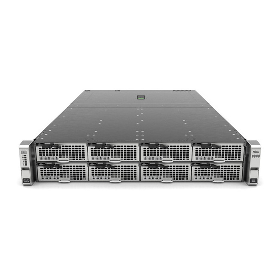
Page 9: Components Front Panel
Maintenance Replaceable Components Overview Replaceable Components Overview This section provides an overview of replaceable components of the Cisco UCS M4308 Modular Server. Components Front Panel Figure 4: Cisco UCS M4308 Chassis Front Panel Compute cartridge (slot 1) Compute cartridge (slot 5) - Page 10 This system supports up to eight single-wide compute cartridges or up to four double-wide cartridges. You can mix single-wide and double-wide cartridges in the same chassis, but a double-wide cartridge cannot install into two slots that straddle the center chassis divider. Cisco UCS M4308 Modular Chassis Installation Guide...
- Page 11 Step 2 Open the cartridge lever to disengage. Step 3 Slide the cartridge out of chassis. Figure 6: Cisco UCS M142 Compute Cartridge Removal Cartridge locking mechanism Center chassis divider Cartridge removal lever Cisco UCS M4308 Modular Chassis Installation Guide...
-
Page 12: Inside The Chassis
Step 6 Close the cartridge lever to lock the cartridge into the chassis. Inside the Chassis This section describes the replaceable components within the chassis. Figure 7: Cisco UCS M4308 Chassis Component Overview Cisco UCS M4308 Modular Chassis Installation Guide... - Page 13 No user actions are required after you replace the battery and restore power. The system automatically synchs with UCS Manager. The battery type is CR2032. Cisco supports the industry-standard CR2032 battery, which can be purchased from most electronic stores.
- Page 14 Maintenance PCIe Adapter Card Replacement Figure 8: Internal RTC Battery Location RTC battery in vertical holder PCIe Adapter Card Replacement This section describes the replacement of the internal PCIe card. Cisco UCS M4308 Modular Chassis Installation Guide...
- Page 15 Align the new PCIe card with the empty socket on the motherboard and the rear panel opening. b) Carefully push down on both ends of the PCIe card to fully engage its circuit board connector with the socket on the motherboard. Cisco UCS M4308 Modular Chassis Installation Guide...
- Page 16 Replace the top cover to the chassis. Step 6 Replace power cords and power on the chassis. Figure 9: PCIe Adapter Card Replacement PCIe adapter card in vertical socket on PCIe card retainer motherboard Cisco UCS M4308 Modular Chassis Installation Guide...
- Page 17 Maintenance RAID Controller Card Replacement RAID Controller Card Replacement This section describes the replacement of the internal RAID controller card. Only Cisco supported RAID controller cards can be used for replacement. Note Procedure Step 1 Power off the chassis and remove power cords from all power supplies.
-
Page 18: Drive Replacement
Observe these drive population guidelines for optimum performance: • When populating drives, add drives to the lowest-numbered bays first. • Keep an empty drive blanking tray in any unused bays to ensure proper air flow. Cisco UCS M4308 Modular Chassis Installation Guide... -
Page 19: Fan Module Replacement
Figure 11: Drive Replacement Drive tray release button Drive tray ejector lever Fan Module Replacement You do not have to shut down or power off the server to replace fan modules because the are hot-swappable. Cisco UCS M4308 Modular Chassis Installation Guide... - Page 20 Press down gently on the fan module until the latch clicks and locks in place. Step 4 Replace the top cover to the chassis. Figure 12: Fan Module Replacement Fan module number Fan module release latches Air flow direction (front-to-back) Cisco UCS M4308 Modular Chassis Installation Guide...
-
Page 21: Power Supply Replacement
Push the power supply into the bay until the release lever locks. c) Connect the power cord to the new power supply. Figure 13: Power Supply Replacement Power supply handle Power supply release lever Cisco UCS M4308 Modular Chassis Installation Guide... - Page 22 Maintenance Power Supply Replacement Cisco UCS M4308 Modular Chassis Installation Guide...
Need help?
Do you have a question about the UCS M4308 and is the answer not in the manual?
Questions and answers