Table of Contents
Advertisement
Quick Links
Advertisement
Table of Contents

Related Manuals for Cisco UCS C4200


Summary of Contents for Cisco UCS C4200
- Page 1 Cisco UCS C4200 Server Chassis Installation and Service Guide First Published: 2018-08-09 Last Modified: 2020-08-10 Americas Headquarters Cisco Systems, Inc. 170 West Tasman Drive San Jose, CA 95134-1706 http://www.cisco.com Tel: 408 526-4000 800 553-NETS (6387) Fax: 408 527-0883...
- Page 2 Cisco has more than 200 offices worldwide. Addresses and phone numbers are listed on the Cisco website at www.cisco.com/go/offices. Cisco and the Cisco logo are trademarks or registered trademarks of Cisco and/or its affiliates in the U.S. and other countries. To view a list of Cisco trademarks, go to this URL: https://www.cisco.com/c/en/us/about/legal/trademarks.html.
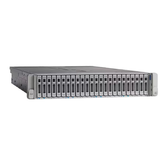
- Page 3 6 front-loading drives in the chassis, for a total of up to 24 small form-factor (SFF), 2.5-inch, SAS/SATA HDDs or SSDs. With Cisco IMC 4.0(2) and later, each of the four compute nodes can control two front-loading NVMe SSDs, for a total of up to eight NVME SSDs in the chassis.
- Page 4 Cisco UCS C4200 Chassis Rear Panel Features The exact features depend on how many compute nodes are installed in the node bays and which cards are installed in the nodes. The sample figure below shows a chassis with four Cisco UCS C125 M5 compute nodes installed.
- Page 5 For definitions of LED states, see Rear-Panel LEDs, on page Figure 2: Cisco UCS C4200 Chassis Rear Panel (Shown With Four C125 M5 Compute Nodes Installed) PCIe riser 1 handle (one each node) Node Power button/Power status LED (one each node) •...
- Page 6 For components inside a compute node, see the service note for your compute node: • Cisco UCS C125 Compute Node Service Note Figure 3: Cisco UCS C4200 Chassis Serviceable Component Locations Cisco UCS C4200 Server Chassis Installation and Service Guide...
- Page 7 Baseboard management Each compute node has a BMC, running Cisco Integrated Management Controller (Cisco IMC) firmware. Depending on your settings, Cisco IMC can be accessed on each node through its 1-Gb dedicated management port or an adapter card. Cisco UCS C4200 Server Chassis Installation and Service Guide...
- Page 8 Each fan module contains two fans for redundancy. PCIe I/O Each removeable compute node has two PCIe risers for horizontal installation of PCIe cards such as a RAID controller or Cisco Virtual Interface Card (VIC). Storage, front-panel The chassis can hold up to 24 front-loading, 2.5-inch drives. Each of the four removeable compute nodes can control six of the front drives.
- Page 9 Integrated video Integrated VGA video in each compute node. The DB-15 VGA connector is on the KVM cable that can be used with the KVM connector on each node. Cisco UCS C4200 Server Chassis Installation and Service Guide...
- Page 10 Overview Summary of Server Features Cisco UCS C4200 Server Chassis Installation and Service Guide...
-
Page 11: Table Of Contents
Initial Compute Node Setup, on page 16 • NIC Mode and NIC Redundancy Settings, on page 21 • Updating the BIOS and Cisco IMC Firmware, on page 22 • Accessing the System BIOS, on page 23 • Smart Access Serial, on page 23 •... -
Page 12: Installation Warnings And Guidelines
Caution Avoid uninterruptible power supply (UPS) types that use ferroresonant technology. These UPS types can become unstable with systems such as the Cisco UCS, which can have substantial current draw fluctuations from fluctuating data traffic patterns. When you are installing a server, use the following guidelines: •... -
Page 13: Rack Requirements
50 to 95°F (10 to 35°C). The Cisco R-Series Racks are an ideal choice. If you use other racks, the rack must be of the following type: • A standard 19-in. (48.3-cm) wide, four-post EIA rack, with mounting posts that conform to English universal hole spacing, per section 1 of ANSI/EIA-310-D-1992. -
Page 14: Installing The Server Chassis In A Rack
Adjust the slide-rail length, and then push the rear mounting pegs into the corresponding rear rack-post holes from the inside of the rack post. You must push aside the spring-loaded securing clip that wraps around the rear rack post. Note The slide rail must be level front-to-rear. Cisco UCS C4200 Server Chassis Installation and Service Guide... - Page 15 (Optional) Secure the server in the rack more permanently by using the two screws that are provided with the slide rails. Perform this step if you plan to move the rack with servers installed. Cisco UCS C4200 Server Chassis Installation and Service Guide...
-
Page 16: Installing The Cable Management Arm (Optional)
CMA tab on arm closest to the server attaches Rear of server to end of inner slide rail attached to server. Cisco UCS C4200 Server Chassis Installation and Service Guide... -
Page 17: Reversing The Cable Management Arm (Optional)
180 degrees so that it points toward the rear of the server. Figure 8: Reversing the CMA CMA tab on end of width-adjustment slider Metal button on outside of tab Cisco UCS C4200 Server Chassis Installation and Service Guide... -
Page 18: Initial Compute Node Setup
• Local setup—Use this procedure if you want to connect a keyboard and monitor directly to the compute node for setup. This procedure can use a KVM cable (Cisco PID N20-BKVM) or the ports on the rear of the server. - Page 19 LED is amber. Step 2 Connect an optional KVM cable (Cisco PID N20-BKVM) to the KVM connector on the face of the node. Connect your USB keyboard and VGA monitor to the KVM cable. Step 3 Open the Cisco IMC Configuration Utility: a) Press and hold the node power button for four seconds to boot the node.
- Page 20 Allow your preconfigured DHCP server to assign an IP address to the node. Step 4 Use the assigned IP address to access and log in to the Cisco IMC for the server node. Consult with your DHCP server administrator to determine the IP address.
- Page 21 Cisco UCS Manager system because the server is in standalone mode, further DHCP requests from the Cisco VIC are disabled. If you want to connect to Cisco IMC through a Cisco VIC in standalone mode, it is recommended that you use the Cisco Card NIC mode.
- Page 22 This compute node has a range of six MAC addresses assigned to the Cisco IMC. The MAC address printed on the label is the beginning of the range of six contiguous MAC addresses.
-
Page 23: Nic Mode And Nic Redundancy Settings
What to do next Use a browser and the IP address of the Cisco IMC to connect to the Cisco IMC management interface. The IP address is based upon the settings that you made (either a static address or the address assigned by your DHCP server). -
Page 24: Updating The Bios And Cisco Imc Firmware
When you upgrade the BIOS firmware, you must also upgrade the Cisco IMC firmware to the same version or the server does not boot. Do not power off the server until the BIOS and Cisco IMC firmware are matching or the server does not boot. -
Page 25: Accessing The System Bios
Cisco IMC CLI. • This feature has the following requirements when used with compute nodes: • A DB-9 serial cable connection, using the KVM cable (Cisco PID N20-BKVM) on the KVM console connector on the face of the compute node. - Page 26 • Disabled: the USB device is connected to the host. • In a case where no management network is available to connect remotely to Cisco IMC, a Device Firmware Update (DFU) shell over serial cable can be used to generate and download technical support files to the USB device that is attached to the node USB port.
- Page 27 Opening the Chassis Compartment Covers, on page 33 • Removing and Replacing Components, on page 35 Status LEDs and Buttons This section contains information for interpreting LED states. Front-Panel LEDs Figure 9: Front Panel LEDs Cisco UCS C4200 Server Chassis Installation and Service Guide...
- Page 28 Temperature status • Green—The system is operating at normal temperature. • Amber, steady—One or more temperature sensors breached the critical threshold. • Amber, blinking—One or more temperature sensors breached the non-recoverable threshold. Cisco UCS C4200 Server Chassis Installation and Service Guide...
- Page 29 The power supply LEDs are the only rear-panel LEDs native to the chassis. Compute node LEDs that repeat on each compute node are also described below. The rear ports and LEDs vary, depending on which adapter card and PCIe cards are installed. Cisco UCS C4200 Server Chassis Installation and Service Guide...
- Page 30 Node 1-Gb Ethernet dedicated management link speed • Off—Link speed is 10 Mbps. (One each node) • Amber—Link speed is 100 Mbps. • Green—Link speed is 1 Gbps. Cisco UCS C4200 Server Chassis Installation and Service Guide...
- Page 31 Internal Diagnostic LEDs in the Chassis The fan tray in the chassis includes a fault LED for each of the fan modules. The four LEDs are numbered to correspond to the four numbered fan modules. Cisco UCS C4200 Server Chassis Installation and Service Guide...
- Page 32 The C4200 system chassis does not include a physical power button. All of the component replacement in the chassis can be performed without removing chassis power (assuming two power supplies with 1+1 redundancy). Cisco UCS C4200 Server Chassis Installation and Service Guide...
- Page 33 Step 1 In the Navigation pane, click the Chassis tab. Step 2 On the Chassis tab, click Summary. Step 3 In the toolbar above the work pane, click the Host Power link. Cisco UCS C4200 Server Chassis Installation and Service Guide...
- Page 34 The operating system performs a graceful shutdown and the node goes to standby mode, which is indicated by an amber Power button/LED. Shutting Down a Node Using The Cisco UCS Manager Equipment Tab You must log in with user or admin privileges to perform this task.
- Page 35 Maintaining the Server Chassis Shutting Down a Node Using The Cisco UCS Manager Service Profile The operating system performs a graceful shutdown and the server goes to standby mode, which is indicated by an amber Power button/LED. Shutting Down a Node Using The Cisco UCS Manager Service Profile You must log in with user or admin privileges to perform this task.
- Page 36 Close the hinged cover: a) With the latch in the fully open position, close the hinged cover. b) Press the cover latch down to the closed position. The cover is pushed forward. Cisco UCS C4200 Server Chassis Installation and Service Guide...
- Page 37 Tighten the single captive screw on the cover. Removing and Replacing Components This section describes how to install or replace components in the Cisco UCS C4200 Server Chassis. For information on replacing components inside an installed compute node, see the service note for your compute node: •...
- Page 38 Maintaining the Server Chassis Serviceable Components in the Chassis Figure 13: Cisco UCS C4200 Chassis Serviceable Component Locations Front-loading drives Cooling fan modules (four) Node 1-controlled drive bays 1—6 Each fan module contains two fans for redundancy. All six bays support SAS/SATA drives; bays 1 and 2 also support NVME drives.
- Page 39 (virtual drive) that contains a mix of hard drives and SSDs. That is, when you create a logical volume, it must contain all SAS/SATA hard drives or all SAS/SATA SSDs. Cisco UCS C4200 Server Chassis Installation and Service Guide...
- Page 40 Setting Up UEFI Mode Booting in the Cisco IMC GUI Step 1 Use a web browser and the IP address of the compute node to log into the Cisco IMC GUI management interface. Step 2 Navigate to Server > BIOS.
- Page 41 With the ejector lever on the drive tray open, insert the drive tray into the empty drive bay. c) Push the tray into the slot until it touches the backplane, and then close the ejector lever to lock the drive in place. Cisco UCS C4200 Server Chassis Installation and Service Guide...
- Page 42 This section is for replacing 2.5-inch NVMe solid-state drives (SSDs) in front-panel drive bays. Caution NVMe drives are not hot-swappable. You can replace them while the system is running, but you must shut down the drive in the software or OS before removal. Cisco UCS C4200 Server Chassis Installation and Service Guide...
- Page 43 Maintaining the Server Chassis Front-Loading NVMe SSD Population Guidelines Note NVMe drives are supported only with Cisco IMC/BIOS 4.0(2) and later; they are supported with Cisco UCS Manager 4.0(2) and later. Front-Loading NVMe SSD Population Guidelines Each compute node in the chassis controls six drive bays. Drive bays 1 and 2 in each set of six bays support NVMe SSDs.
- Page 44 Observe the drive-tray LED and wait until it returns to solid green before accessing the drive: • Off—The drive is not in use. • Green, blinking—the driver is initializing following hot-plug insertion. • Green—The drive is in use and functioning properly. Cisco UCS C4200 Server Chassis Installation and Service Guide...
- Page 45 There are four fault LEDs on the fan tray, each numbered to a corresponding fan module. These LEDs light green when the fan is correctly seated and is operating OK. The LED lights amber when the fan has a fault or is not correctly seated. Cisco UCS C4200 Server Chassis Installation and Service Guide...
- Page 46 Press the cover latch down to the closed position. The cover is pushed forward. c) If desired, lock the latch by using a screwdriver to turn the lock 90-degrees clockwise. Cisco UCS C4200 Server Chassis Installation and Service Guide...
- Page 47 If you cannot safely view and access the component, remove the server from the rack. Step 2 Open the supercap compartment cover: a) Use a #1 Phillips-head screwdriver to loosen the single captive screw on the cover. Cisco UCS C4200 Server Chassis Installation and Service Guide...
- Page 48 The server can have one or two power supplies. When two power supplies are installed they are redundant as 1+1. • See also Power Specifications, on page 52 for more information about the supported power supplies. Cisco UCS C4200 Server Chassis Installation and Service Guide...
- Page 49 Connect the power cord to the new power supply. d) Only if you shut down the compute nodes, reboot each to main power mode. Figure 20: Replacing AC Power Supplies Power supply release lever Power supply handle Cisco UCS C4200 Server Chassis Installation and Service Guide...
- Page 50 For information about replacing a mini-storage carrier with SD cards or M.2 SATA drives inside a compute node, see the service note for your compute node: • Cisco UCS C125 Compute Node Service Note Cisco UCS C4200 Server Chassis Installation and Service Guide...
- Page 51 For information about supported storage controllers and replacing a controller card inside a compute node, see the service note for your compute node: • Cisco UCS C125 Compute Node Service Note Cisco UCS C4200 Server Chassis Installation and Service Guide...
- Page 52 Maintaining the Server Chassis Replacing a Storage Controller Inside a Compute Node Cisco UCS C4200 Server Chassis Installation and Service Guide...
- Page 53 (width of the chassis rail-receiving surface; not including front latch-handles) Depth (length) Server only: 32.6 in. (827.6 mm) Server with Cisco slide rails and CMA: 38.0 in (965.2 mm) Maximum weight 95.8 lb. (43.5 Kg) (fully loaded chassis with four compute nodes) Environmental Specifications The following table lists the environmental requirements for the C4200 server chassis.
- Page 54 Power Specifications Note Do not mix power supply types or wattages in the server. Both power supplies must be identical. You can get more specific power information for your exact server configuration by using the Cisco UCS Power Calculator: http://ucspowercalc.cisco.com The power specifications for the supported power supply options are listed in the following sections.
- Page 55 Only the approved power cords or jumper power cords listed below are supported. Table 7: Supported Power Cords Description Length (Feet) Length (Meters) Argentina 4.26 CAB-IR2073-C19-AR AC power cord, 16 A, 250 VAC Plugs: IRSM 2073 to IEC 60320 C19 Cisco UCS C4200 Server Chassis Installation and Service Guide...
- Page 56 CAB-S132-C19 AC power cord, 16 A, 250 VAC Plugs: S132 to IEC 60320 C19 Italy 4.26 CAB-C2316-C19-IT AC power cord, 16 A, 250 VAC Plugs: CEI 23-16 to IEC 60320 C19 Cisco UCS C4200 Server Chassis Installation and Service Guide...
- Page 57 AC power cord, 16 A, 250 VAC Plugs: TW1-15P to IEC 60320 C19 Switzerland CAB-ACS-16 AC power cord, 16 A, 250 VAC Plugs: SEV 5934-2, Type 23 to IEC 60320 C19 Cisco UCS C4200 Server Chassis Installation and Service Guide...
- Page 58 Plugs: NEMA 6-20 to IEC 60320 C19 Cabinet Jumper Power Cord CAB-C19-CBN AC power cord, 16 A, 250 VAC Plugs: IEC 60320 C20 to IEC 60320 C19 No power cord option R2XX-DMYMPWRCORD Cisco UCS C4200 Server Chassis Installation and Service Guide...
- Page 59 All nodes in a C4200 chassis must be either all managed in standalone mode or all managed in UCSM mode. Mixing in a chassis is not supported. Also refer to the release notes for Cisco UCS Manager software and C-Series Cisco IMC software for any special considerations regarding integration in your release.
- Page 60 Installation For Cisco UCS Manager Integration Installation For Cisco UCS Manager Integration Cisco UCS C4200 Server Chassis Installation and Service Guide...
Need help?
Do you have a question about the UCS C4200 and is the answer not in the manual?
Questions and answers