Table of Contents
Advertisement
Advertisement
Table of Contents

Related Manuals for Nakanishi E3000 SELECTOR

Summary of Contents for Nakanishi E3000 SELECTOR
- Page 1 取扱説明書 / OPERATON MANUAL 日本語 : P1 - P26 / English : P29 - P58 OM-K0442 002...
-
Page 2: Table Of Contents
(rpm) . This system utilizes air to cool the motor and protect the spindle. Always use an capable of 80,000 min NAKANISHI Air Line Kit to ensure clean, dry, properly regulated air is supplied to the motor and spindle. The E3000 Read this and all the associated component system is capable of being used with coolants and cutting lubricants. -
Page 3: Important Instructions And Warning - Electric Devices
1) Please refer to the pin diagram below for the proper wiring con¿guration. The plug shown is the female plug that attaches to the E3000 SELECTOR main power inlet. 2) Make sure you test each individual wire to verify proper circuit prior to attaching any wire to the terminal block. - Page 4 2. Replace cracked collet or collet nut immediately. 3. Do not over tighten the collet nut. 4. Use only NAKANISHI manufactured collets and arbors for grinding and sawing applications. 5. REMOVE ADJUSTING KEYS AND WRENCHES. Always check to see that keys and adjusting wrenches are removed from tool before turning the units main power switch on.
-
Page 5: Cautions For Handling And Operation
1. CAUTIONS FOR HANDLING AND OPERATION ■ Read these warnings and cautions carefully and only use in the manner intended. ■ These warnings and cautions are intended to avoid potential hazards that could result in personal injury to the operator or damage to the device. These are classi¿ed as follows in accordance with the seriousness of the risk. Class Degree of Risk A safety hazard could result in bodily injury or damage to the device if... - Page 6 Attach the provided connector cap (for motor output) and air plug (for air stoppage) for safety and dust proo¿ng when not using SELECTOR. ⑫ Connect to the E3000 CONTROLLER when using E3000 SELECTOR. ⑬ When disposal of CONTROLLER or SELECTOR is necessary, follow the instructions from each local government and dispose as an industrial waste.
-
Page 7: Basic Package
When opening the package, check if it includes all items listed in " Table.1 Packing List Contents ". In the event of any shortage, please contact either NAKANISHI (see the " 4. CONTACT US " section) or your local dealer. -
Page 8: Warranty
(closed Saturday, Sunday and Public Holidays) Telephone No. : +81 (0) 289-64-3520 e-mail Address : webmaster-ie@nsk-nakanishi.co.jp 5 . FEATURES ① Up to 4 motors can be connected to selector providing individual control of each motor. (4 motors cannot be run simultaneously) ②... -
Page 9: Specifications And Dimensions
Motor speed limits depend on the Motor Model. Before using, refer to the P54 " 6 - 1 Speci¿cations Note : 1 " section of the E3000 CONTROLLER Operation Manual. 6 - 2 Compatibility (1) The E3000 SELECTOR is compatible with the following overseas safety standards. ‡ Safety standard in North America (UL,CSA) UL508C CSA C22.2 No. - Page 10 6 - 3 Outside View *Below is an outside view with Brackets (Standard Accessory) attached. M4 x 0.7 Stepped Bracket Fig. 1 Bottom Mounting 86.2 M4 x 0.7 Stepped Bracket Fig. 2 Rear Mounting...
-
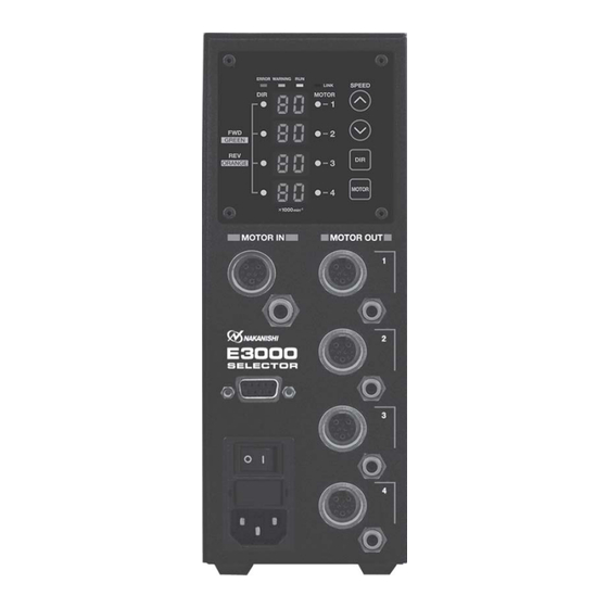
Page 11: Control Panel Features
Connect the provided Communication Cable to the E3000 CONTROLLER Serial I /F Connector to the E3000 SELECTOR Serial I/F Connector. Attach the provided Serial I /F Connector Cover for safety and dust proo¿ ng, when not using E3000 SELECTOR. ⑭ Main Power Switch ON / OFF main power source. - Page 12 Fig. 4 ⑯ Error LED (ERROR) When a problem with the E3000 SELECTOR, or motor alarms are detected, this LED illuminates. The motor may shut down and the Digital Speed Indicator in E3000 CONTROLLER Control Panel will display an error code.
-
Page 13: Replacing The Fuses
8 . REPLACING THE FUSES WARNING ・ Before removing the fuse holder and fuses, be sure that the Main Power Switch ⑭ is turned OFF and remove the Power Cord has been removed from the SELECTOR. ・ Verify type and use only following the properly rated and type of fuse. Speci¿... - Page 14 9 - 2 Installation of the Rubber Pad Caution when installing the SELECTOR horizontally ・ When rotating the direction of Control Panel ② , ensure that the Main Power Switch ⑭ is turned OFF and the Power Cord has been removed from the SELECTOR. ・...
-
Page 15: Power Cord Connection
10 . POWER CORD CONNECTION WARNING Only use grounded power sources. Failure to properly ground the SELECTOR may result in electric shock, injury, ¿ re and / or damage to the system components. CAUTION ・ When connecting the Power Cord Plug, make sure the Main Power Switch ⑭ is turned OFF. ・... -
Page 16: Connection Of The E 3000 Controller To The Selector
Connect provided Communication Cable (length : 60 cm) to Serial I / F Connector on the E3000 CONTROLLER and Serial I / F Connector ⑬ on the E3000 SELECTOR. After connecting, be sure to tighten the mounting screws of the Communication Cable (length : 60cm). - Page 17 (1) Connection to the Air Input Joint CAUTION When not using NAKANISHI Air Line Kit, make sure that the incoming air supply is dry, clean and properly regulated. 6mm air hose with ¿ lter from the AL - C1204 Air Line Kit into the Air Input Joint ⑫ on the front Insert the provided of the SELECTOR.
- Page 18 SELECTOR ④ Air Output Joint ⑫ Air Input Joint 4mm cooling Air Hose 6mm Air Hose ⑥ Air Output Joint with Filter ⑧ Air Output Joint ⑩ Air Output Joint Fig. 18 (4) CONTROLLER to SELECTOR Connections CONTROLLER SELECTOR Air Plug ( For Air Stop : 6)...
-
Page 19: Operation Procedures
When using Manual Mode with the CONTROLLER and SELECTOR combination, the following functions will be controlled from the front panel of the respective units. E3000 CONTROLLER E3000 SELECTOR Motor Speed Motor Selection Gear mode operation and selection Motor Start / Stop... - Page 20 (1) Set Motor Selection (Set the Motor Selection Button (MOTOR) ㉓ of the Fig. 22 SELECTOR Control Panel.) Motor No.1 - No.4 ( ③ , ⑤ , ⑦ , ⑨ ) is selected by pushing the Motor Selection Button (MOTOR) ㉓ . LED ⑳ The corresponding motor selected LED will be illuminated.
- Page 21 ⑱ ⑲ ⑳ Ⓔ Ⓖ Ⓑ Ⓕ ㉑ ㉔ ㉒ ㉓ ㉕ Ⓓ Ⓒ Fig. 22 SELECTOR Control Panel Fig. 23 CONTROLLER Control Panel (6) Motor Start / Stop (Motor Start / Stop by pushing the START / STOP Button (START / STOP) Ⓒ of the Fig. 23 CONTROLLER Control Panel) The motor spindle will start and the LED will illuminate.
- Page 22 When rotation speed is set 30,000min (rpm) When rotation speed is set 30,000min (rpm) and Gear Ratio is set 1.5 and Gear Ratio is set 1.0 ⑪ ⑪ Dot will Blink. Dot turns OFF. When Gear Ratio "1.5 / 2.7 / 4.0 / 6.0 / 16" is set, the When Gear Ratio is set, the dot displayed dot displayed on Digital Speed Indicator ⑪...
-
Page 23: External Input / Output Connector Of The Controller
14 . EXTERNAL INPUT / OUTPUT CONNECTOR OF THE CONTROLLER Table. 3 details in External Input / Output Connector A Signals. Make sure to refer to the Operation Manual of the E3000 CONTROLLER. WARNING ・ DO NOT connect any circuit other than SELV (DC+24V) (Safety Extra Low Voltage) to the External Input / Output Connector A of the CONTROLLER. - Page 24 Input / Code Function Description Output ' OFF (Open) ' : Stop Rotating Output Output shows that the motor is rotating. ' ON (Closed) ' : Rotating Rotating ' OFF (Open) ' : FWD. Output shows the direction of the Motor is DIR_OUT Output Direction...
- Page 25 Input / Code Function Description Output Use when selecting motor, after connecting CONTROLLER to the SELECTOR. 4 motors can be selected by SEL0 and Motor Select 0 SEL1 combination. (Refer to P69 "15 - 2 - 2 (7) Motor Selection Table. 4 of the E3000 SEL0 Input ―...
- Page 26 (2) Input / Output Diagram COM_1 (DC+24V or DC0V) START DIR_OUT DIR_IN RESET WARNING 500min (rpm) COIN Input / Output SEL0 Connector A (D-Sub25) SEL1 PULSE UD_IN COM_2 (DC0V or DC+24V) CNT_IN MOTOR_I +10VDC LOAD Variable Resistor 5KΩ SPEED_V MT-CNA MT-CNB AUTO+ EMG-INA...
- Page 27 (3) Input / Output Signal ① Input Signal There are 8 different input signals : "Rotate Command (START)", "Rotating Direction Setting (DIR_IN)", "Rotates Motor at "Centering" speed (500min (rpm))", "Error Release (RESET)", "UP / DOWN Signal for Setting Motor Speed (UD_IN)", "Count Pulse Signal for Setting Motor Speed (CNT_IN)", "Motor Select 0 (SEL0)", and "Motor Select 1 (SEL1)".
- Page 28 ③ Output Signal Refer to Fig. 28 regarding the Output Signal of the Rotating Pulse (PULSE). The output signal can be connected for either sinking or sourcing. Voltage and Current Speci¿cations ・Applied Voltage (V) ≦ DC+30V ・Working Current (lp) ≦ 50mA DC+24V or DC0V The side of CONTROLLER (COM_2)
- Page 29 Torque Characteristics.( parameter is 80,000min (rpm) 60,000min (rpm) 50,000min (rpm) 32,000min (rpm) 30,000min (rpm) 0.15 VR (DCV) Motor type Description Max. 80,000min (rpm) DC+9.0V・・・60,000min (rpm) Max. 60,000min (rpm) Max. 50,000min (rpm) DC+7.5V・・・ 50,000min (rpm) Max. 32,000min (rpm) DC+4.8V・・・ 32,000min (rpm) Max.
-
Page 30: Troubleshooting
15 . TROUBLESHOOTING If a problem or concern occurs, please check the following prior to consulting your dealer. (Make sure read Operation Manual of the E3000 CONTROLLER.) Trouble Cause Inspection / Corrective Action ・ Make sure to turn ON the Main Power Motor does not run. -
Page 31: Disposal Of The Selector
Trouble Cause Inspection / Corrective Action Motor speed is not Motor Fixed Speed is set in the Release parameter . (Refer to P84 displayed correctly. parameter. " 18 - 3 ③ Setting Fixed Motor Speed " section of the E3000 CONTROLLER Operation Manual.) Motor Maximum Speed is set in the Release parameter... - Page 33 2015 . 04 . 20 001...
Need help?
Do you have a question about the E3000 SELECTOR and is the answer not in the manual?
Questions and answers