Table of Contents
Advertisement
Available languages
Available languages
Quick Links
Advertisement
Chapters
Table of Contents

Related Manuals for baltur TBG 35P


Summary of Contents for baltur TBG 35P
- Page 1 BRUCIATORI DI GAS BISTADIO TWO-STAGE GAS BURNERS ITALIANO TBG 35P Manuale istruzioni per l'installazione, l'uso e la manutenzione Instruction manual for installation, use and maintenance ISTRUZIONI ORIGINALI (IT) ORIGINAL INSTRUCTIONS (IT) 0006160258_201802...
-
Page 3: Table Of Contents
ITALIANO ITALIANO SOMMARIO Avvertenze per l'uso in condizioni di sicurezza ............................3 Caratteristiche tecniche ...................................6 Materiale a corredo ...................................7 Targa identificazione bruciatore.................................7 Dati registrazione prima accensione ..............................7 Descrizione componenti ..................................8 Quadro elettrico ....................................8 Campo di lavoro ....................................9 Dimensioni di ingombro ...................................10 Caratteristiche tecnico funzionali .............................. - Page 4 ITALIANO DICHIARAZIONE DI CONFORMITÀ CE0085: DVGW CERT GmbH, Josef-Wirmer Strasse 1-3-53123 Bonn (D) Dichiariamo che i nostri bruciatori ad aria soffiata di combustibili gassosi e misti, serie: BPM...; BGN…; BTG…; TBML...; Comist…; GI…; GI…Mist; Minicomist…; Sparkgas...; TBG..; IB..; TBR... (Variante: … LX, per basse emissioni NOx; -V per inverter, FGR per ricircolazione esterna fumi) rispettano i requisiti minimi imposti dalle Direttive e Regolamenti europei: •...
-
Page 5: Avvertenze Per L'uso In Condizioni Di Sicurezza
ITALIANO AVVERTENZE PER L'USO IN CONDIZIONI sull'apparecchio. • L'apparecchio non è adatto a essere usato da persone (bambini DI SICUREZZA compresi) le cui capacità fisiche, sensoriali o mentali siano ridotte, oppure con mancanza di esperienza o di conoscenza. SCOPO DEL MANUALE •... - Page 6 • L’eventuale riparazione dei prodotti dovrà essere effettuata • Prima di avviare il bruciatore e almeno una volta all’anno, solamente da un centro di assistenza autorizzato da BALTUR o far effettuare da personale professionalmente qualificato le dal suo distributore locale, utilizzando esclusivamente ricambi seguenti operazioni: originali.
- Page 7 ITALIANO Avvertenze particolari per l’uso del gas. • L’alimentazione elettrica del bruciatore deve prevedere il neutro • Verificare che la linea di adduzione e la rampa siano conformi a terra. In caso di controllo della corrente di ionizzazione con alle norme e prescrizioni vigenti. neutro non a terra è...
-
Page 8: Caratteristiche Tecniche
ITALIANO CARATTERISTICHE TECNICHE MODELLO TBG 35P POTENZA TERMICA MASSIMA METANO POTENZA TERMICA MINIMA METANO mg/kWh ¹) EMISSIONI METANO Classe 3 FUNZIONAMENTO Bistadio TRASFORMATORE METANO 50 Hz 26 kV - 40 mA - 230/240 V TRASFORMATORE METANO 60 Hz 26 kV - 40 mA - 220/230 V Stm³/h... -
Page 9: Materiale A Corredo
ITALIANO MATERIALE A CORREDO MODELLO TBG 35P FLANGIA ATTACCO BRUCIATORE GUARNIZIONE ISOLANTE Classe 3 PRIGIONIERI N° 4 M 12 DADI ESAGONALI N° 4 M 12 RONDELLE PIANE N° 4 Ø 12 ¹) EMISSIONI GAS METANO ²) EMISSIONI GAS PROPANO Classi definite secondo la normativa EN 676. -
Page 10: Descrizione Componenti
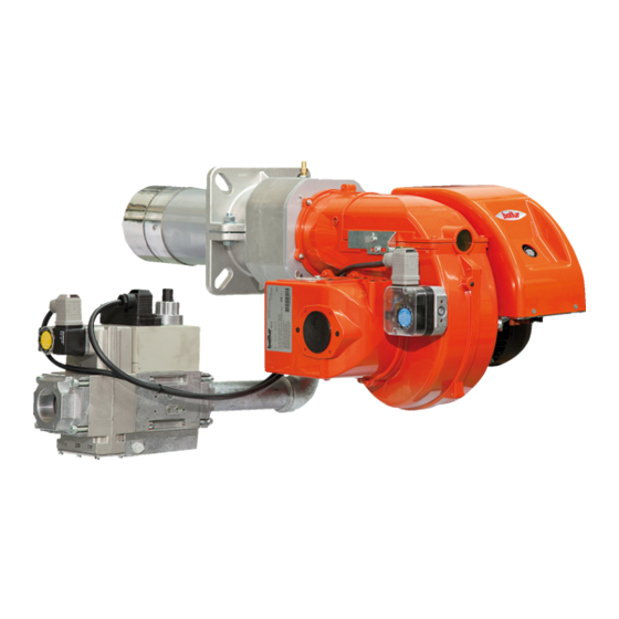
ITALIANO DESCRIZIONE COMPONENTI Testa di combustione Guarnizione Flangia attacco bruciatore Dispositivo regolazione testata Coperchio chiocciola Flangia attacco rampa gas Quadro elettrico Motore Servomotore regolazione aria Pressostato aria Targa identificazione bruciatore QUADRO ELETTRICO Trasformatore d'accensione Pulsate di sblocco Apparecchiatura Connettore 7 poli Connettore 4 poli 8 / 34 0006160258_201802... -
Page 11: Campo Di Lavoro
ITALIANO CAMPO DI LAVORO mbar TBG 35 P / PN TBG 35 MC / ME /h (Metano) /h (G.P.L.) IMPORTANTE I campi di lavoro sono ottenuti su caldaie di prova rispondenti alla norma EN676 e sono orientativi per gli accoppiamenti bruciatore- caldaia. -
Page 12: Dimensioni Di Ingombro
ITALIANO DIMENSIONI DI INGOMBRO Modello TBG 35P Modello E Ø F Ø IØ LØ N Ø TBG 35P 140 ÷ 300 200 ÷ 245 10 / 34 0006160258_201802... -
Page 13: Caratteristiche Tecnico Funzionali
ITALIANO CARATTERISTICHE TECNICO FUNZIONALI CARATTERISTICHE COSTRUTTIVE • Bruciatore di gas conforme alle normative europee EN 676 I bruciatori risultano composti da: ed alle Direttive Europee 2006/42/CE; 2006/95/CE; 97/23/CE; • Presa d'aria comburente con serranda a farfalla per la 2004/108/CE. regolazione della portata d'aria. •... -
Page 14: Linea Di Alimentazione
ITALIANO APPLICAZIONE DEL BRUCIATORE ALLA LINEA DI ALIMENTAZIONE Lo schema di principio della linea di alimentazione gas è riportato CALDAIA nella figura sotto. Installare, a monte della valvola gas, una valvola di intercettazione MONTAGGIO GRUPPO TESTATA manuale e un giunto antivibrante, disposti secondo quanto •... - Page 15 ITALIANO MONTAGGIO RAMPA GAS Sono possibili diverse soluzioni di montaggio (1), (2), (3) , della rampa gas. Il bruciatore viene fornito con attacco per rampa gas rivolto verso il basso. Se si desidera invertire il lato di ingresso rampa per consentire il montaggio della rampa gas secondo la configurazione (1), seguire la procedura descritta al paragrafo:"Predisposizione pre attacco rampa verso l'alto".
-
Page 16: Collegamenti Elettrici
ITALIANO COLLEGAMENTI ELETTRICI AR 1 • Tutti i collegamenti devono essere eseguiti con filo elettrico flessibile. L (1) ION IN • Le linee elettriche devono essere distanziate dalle parti calde. Ph 230 • L’installazione del bruciatore è consentita solo in ambienti con IN (2) ION PROBE grado di inquinamento 2 come indicato nell’allegato M della... -
Page 17: Descrizione Del Funzionamento
ITALIANO DESCRIZIONE DEL FUNZIONAMENTO In caso di “blocco di sicurezza” le valvole vengono immediatamente richiuse. Alla chiusura dell’interruttore generale, se i termostati sono chiusi, Per sbloccare l’apparecchiatura dalla posizione di sicurezza la tensione raggiunge l’apparecchiatura di comando e controllo occorre premere il pulsante Pulsate di sblocco del quadro elettrico. che avvia il bruciatore. -
Page 18: Accensione E Regolazione Gas Metano
ITALIANO ACCENSIONE E REGOLAZIONE GAS METANO • Verificare che ci sia acqua in caldaia e che le saracinesche dell’impianto siano aperte. • Verificare che lo scarico dei prodotti della combustione attraverso le serrande caldaia e serrande camino, possa avvenire liberamente. Controllare che tutte le saracinesche poste sulla tubazione del combustibile siano aperte e così... - Page 19 ITALIANO FUNZIONAMENTO BISTADIO • Verificare che la camma di regolazione portata gas di secondo stadio del servomotore elettrico sia posizionata REGOLAZIONE DELLA POTENZA DI PRIMA ACCENSIONE a 90°. • Per il bruciatore bistadio, posizionare la camma regolazione • Inserire nuovamente il bruciatore chiudendo l'interruttore portata gas di prima fiamma del servomotore, ad un angolo di generale.
- Page 20 ITALIANO • Verificare con gli appositi strumenti i parametri di combustione secondi manderà in blocco il bruciatore per mancata fiamma in primo stadio (CO2 MAX=10% O2 MIN= 3% CO MAX=0,1%) di accensione; • spegnere il bruciatore; REGOLAZIONE DELLA POTENZA IN PRIMO STADIO •...
-
Page 21: Regolazione Aria Sulla Testa Di Combustione
ITALIANO REGOLAZIONE ARIA SULLA TESTA DI COMBUSTIONE focolare. La testa di combustione è dotata di un dispositivo di regolazione che permette di aprire o chiudere il passaggio dell’aria tra il disco e la testa. Chiudendo il passaggio si riesce così ad ottenere, un’elevata pressione a monte del disco anche con le basse portate. -
Page 22: Corrente Di Rilevazione Fiamma
ITALIANO CORRENTE DI RILEVAZIONE FIAMMA La corrente minima di ionizzazione per far funzionare l’apparecchiatura è di 3 μA.La fiamma del bruciatore genera una corrente nettamente superiore, tale da non richiedere normalmente alcun controllo da parte dell’apparecchiatura.Qualora si voglia misurare la corrente di ionizzazione bisogna collegare un microamperometro in serie al cavetto dell’elettrodo di ionizzazione aprendo il connettore “C”, vedi schema elettrico. -
Page 23: Apparecchiatura Di Comando E Controllo Lme
ITALIANO APPARECCHIATURA DI COMANDO E CONTROLLO LME... FUNZIONAMENTO. Il pulsante di sblocco «EK...» è l’elemento principale per poter accedere ROSSO a tutte le funzioni di diagnostica (attivazione e disattivazione), oltre a GIALLO sbloccare il dispositivo di comando e controllo. VERDE Sia «LED»... - Page 24 ITALIANO DIAGNOSI DELLE CAUSE DI MALFUNZIONAMENTO E BLOCCO. In caso di blocco bruciatore nel pulsante di sblocco sarà fissa la luce rossa. Premendo per più di 3 sec. la fase di diagnosi verrà attivata (luce rossa con lampeggio rapido), nella tabella sottostante viene riportato il significato della causa di blocco o malfunzionamento in funzione del numero di lampeggi (sempre colore rosso).
- Page 25 ITALIANO SCHEMA DEI COLLEGAMENTI E CONTROLLO DELLA SEQUENZA DI AGK25... Resistenza PTC LAVORO DELL'APPARECCHIATURA LME 22... Messaggio di errore (allarme) Interfaccia di Comunicazione del Bruciatore BV... Valvola del Combustibile Indicatore di Posizione Chiusa Dbr.. Ponticello cablaggio EK.. Pulsante di reset del blocco remoto (interno) EK2 Pulsante di reset del blocco remoto Sonda di Ionizzazione Segnale di Fiamma...
-
Page 26: Servomotori Regolazione Aria / Combustibile
ITALIANO SERVOMOTORI REGOLAZIONE ARIA / COMBUSTIBILE Schema elettrico Vite di regolazione Camma regolazione aria primo stadio Camma non utilizzata Camma regolazione aria secondo stadio Collegamenti elettrici Indice di riferimento Per modificare la regolazione delle camme, agire sulle rispettive viti.L'indice dell'anello rosso indica sulla rispettiva scala di riferimento l'angolo di rotazione impostato per ogni camma. -
Page 27: Manutenzione
ITALIANO MANUTENZIONE Effettuare almeno una volta all’anno e comunque in conformità alle norme vigenti, l’analisi dei gas di scarico della combustione verificando la correttezza dei valori di emissioni. • Verificare che tutti i componenti della testa di combustione siano in buono stato, non deformati e privi di impurità o depositi derivanti dall'ambiente di installazione e/o da una cattiva combustione. -
Page 28: Tempi Di Manutenzione
ITALIANO TEMPI DI MANUTENZIONE Descrizione particolare Azione da eseguire TESTA DI COMBUSTIONE CONTROLLO VISIVO, INTEGRITA' CERAMICHE, SMERIGLIATURA ESTREMITA', VERIFICARE ELETTRODI ANNUO DISTANZA, VERIFICARE CONNESSIONE ELETTRICA DISCO FIAMMA CONTROLLO VISIVO INTEGRITA' EVENTUALI DEFORMAZIONI, PULIZIA ANNUO CONTROLLO VISIVO, INTEGRITA' CERAMICHE, SMERIGLIATURA ESTREMITA', VERIFICARE SONDA DI IONIZZAZIONE ANNUO DISTANZA, VERIFICARE CONNESSIONE ELETTRICA... -
Page 29: Vita Attesa
ITALIANO VITA ATTESA La vita attesa dei bruciatori e dei relativi componenti dipende molto dal tipo di applicazione su cui il bruciatore è installato, dai cicli, dalla potenza erogata, dalle condizioni dell’ambiente in cui si trova, dalla frequenza e modalità di manutenzione, ecc. ecc. Le normative relative ai componenti di sicurezza prevedono una vita attesa di progetto espressa in cicli e/o anni di funzionamento. -
Page 30: Istruzioni Di Montaggio Riduzioni Per Gpl
ITALIANO ISTRUZIONI DI MONTAGGIO RIDUZIONI PER GPL Nel caso di funzionamento con combustibile GPL inserire le apposite riduzioni fornite a corredo del bruciatore. Per il montaggio delle riduzioni seguire le seguenti indicazioni. Dopo aver allentato le viti di fissaggio (1) rimuovere le riduzioni (A) dalle rispettive sedi. -
Page 31: Precisazioni Sull'uso Del Propano
ITALIANO PRECISAZIONI SULL'USO DEL PROPANO PERICOLO / ATTENZIONE La potenza massima e minima (kW) del bruciatore, • Valutazione, indicativa, del costo di esercizio; è considerata con combustibile metano che coincide - 1 m3 di gas liquido in fase gassosa ha un potere calorifico approssimativamente con quella del propano. -
Page 32: Schema Di Principio Per Riduzione Pressione G.p.l. A Due Stadi Per Bruciatore Oppure Caldaia
ITALIANO SCHEMA DI PRINCIPIO PER RIDUZIONE PRESSIONE G.P.L. A DUE STADI PER BRUCIATORE OPPURE CALDAIA Manometro e presa di pressione Riduttore di 1° salto Riduttore di 2° salto Uscita ~ 1,5 bar Uscita ~ 30 hPa (mbar) Portata ~ il doppio del massimo richiesto Portata ~ il doppio del massimo richiesto dall’utilizzatore dall’utilizzatore... -
Page 33: Istruzioni Per L'accertamento Delle Cause Di Irregolarità Nel Funzionamento E La Loro Eliminazione
ITALIANO ISTRUZIONI PER L'ACCERTAMENTO DELLE CAUSE DI IRREGOLARITÀ NEL FUNZIONAMENTO E LA LORO ELIMINAZIONE IRREGOLARITÁ POSSIBILE CAUSA RIMEDIO Invertire l'alimentazione (lato 230V) del trasformatore di accensione e verificare Disturbo della corrente di con micro-amperometro analogico. ionizzazione da parte del Sostituire il sensore fiamma. trasformatore di accensione. - Page 34 ITALIANO 32 / 34 0006160258_201802...
- Page 35 ITALIANO APPARECCHIATURA CONTROLLO TENUTA VALVOLE FOTORESISTENZA / ELETTRODO DI IONIZZAZIONE / FOTOCELLULA UV SPIA BLOCCO ESTERNA / LAMPADA FUNZIONAMENTO RESISTENZE AUSILIARIE SPIA DI FUNZIONAMENTO MOTORE VENTOLA “CONTAORE“ PRESSOSTATO ARIA PRESSOSTATO GAS TRASFORMATORE D’ACCENSIONE TERMOSTATO CALDAIA TERMOSTATO DI SICUREZZA “TERMOSTATO 2 STADIO“ Y1/Y2 ELETTROVALVOLE 1°...
- Page 36 ITALIANO 34 / 34 0006160258_201802...
- Page 37 ENGLISH ENGLISH SUMMARY Warnings for use in safety conditions ..............................3 Technical specifications ...................................6 Standard accessories ..................................7 Burner identification plate ..................................7 Data recorded during first start-up ..............................7 Component description ..................................8 Electrical panel ....................................8 Operating range ....................................9 Overall dimensions ..................................10 Technical functional characteristics ..............................11 Design characteristics ..................................
- Page 38 ENGLISH DECLARATION OF CONFORMITY CE0085: DVGW CERT GmbH, Josef-Wirmer Strasse 1-3-53123 Bonn (D) We hereby declare under our own responsibility, that our blown air burners fired by gas and dual fuel, series: BPM...; BGN…; BTG…; TBML...; Comist…; GI…; GI…Mist; Minicomist…; Sparkgas...; TBG..; IB..; TBR... (Variant: …...
-
Page 39: Warnings For Use In Safety Conditions
ENGLISH WARNINGS FOR USE IN SAFETY have access to, through a responsible person, the information concerning their safety, surveillance and instructions concerning CONDITIONS equipment use. • Children must be watched over to prevent them from playing PURPOSE OF THIS MANUAL with the equipment. - Page 40 Contact only qualified personnel. accordance with the law in force. • Any product repairs must only be carried out by BALTUR - Check the adjustment and safety devices are working authorised assistance centres or by its local distributor using properly.
- Page 41 ENGLISH Special precautions when using gas. with certain fundamental rules, including the following: • Check that the feed line and the train comply with current law - do not touch the equipment with parts of the body that are and regulations. wet or damp or with damp feet;...
-
Page 42: Technical Specifications
ENGLISH TECHNICAL SPECIFICATIONS MODEL TBG 35P MAXIMUM NATURAL GAS HEAT POWER MINIMUM NATURAL GAS HEAT POWER mg/kWh ¹) NATURAL GAS EMISSIONS Class 3 OPERATION Two-stage 50 Hz NATURAL GAS TRANSFORMER 26 kV - 40 mA - 230/240 V 60 Hz NATURAL GAS TRANSFORMER 26 kV - 40 mA - 220/230 V Stm³/h... -
Page 43: Standard Accessories
ENGLISH STANDARD ACCESSORIES MODEL TBG 35P BURNER CONNECTION FLANGE INSULATING GASKET Class 3 STUD BOLTS No. 4 M 12 HEXAGON NUTS No. 4 M 12 FLAT WASHERS No. 4 Ø 12 ¹) NATURAL GAS EMISSIONS ²) PROPANE GAS EMISSIONS Classes defined according to EN 676 standards. -
Page 44: Component Description
ENGLISH COMPONENT DESCRIPTION Combustion head Seal Burner connection flange Combustion head adjustment device Scroll cover Gas train connector flange Electrical panel Motor Air regulation servomotor Air pressure switch Burner identification plate ELECTRICAL PANEL Ignition transformer Reset button Control box 7-pole connector 4-pole connector 8 / 34 0006160258_201802... -
Page 45: Operating Range
ENGLISH OPERATING RANGE mbar TBG 35 P / PN TBG 35 MC / ME /h (Metano) /h (G.P.L.) IMPORTANT The operating ranges are obtained from test boilers corresponding to Standard EN676 and are indicative of the burner-boiler combination. For correct working of the burner, the size of the combustion chamber must correspond to current regulations; if not the manufacturers must be consulted. -
Page 46: Overall Dimensions
ENGLISH OVERALL DIMENSIONS Model TBG 35P Model E Ø F Ø IØ LØ N Ø TBG 35P 140 ÷ 300 200 ÷ 245 10 / 34 0006160258_201802... -
Page 47: Technical Functional Characteristics
ENGLISH TECHNICAL FUNCTIONAL CHARACTERISTICS DESIGN CHARACTERISTICS • Gas burner compliant with European Standards EN 676 and Burners are composed by: European Directives 006/42/EC; 2006/95/EC; 97/23/EC; • Combustion air intake with throttle gate for the regulation of the 2004/108/EC. air flow rate. •... -
Page 48: Supply Line
ENGLISH BURNER CONNECTION TO THE BOILER SUPPLY LINE The figure below shows the gas supply line block diagram. Install a manual shut-off valve and an anti-vibration joint upstream HEAD UNIT ASSEMBLY of the gas valve, as shown in the diagram. •... - Page 49 ENGLISH ASSEMBLING THE GAS TRAIN The gas train can be assembled in different ways: (1), (2), (3). The burner is supplied with the gas train connection facing downward. If you wish to invert the direction of train entrance to allow the gas train to be assembled in configuration (1) follow the procedure described in the section entitled: "Preparation for connection with train turned upward".
-
Page 50: Electrical Connections
ENGLISH ELECTRICAL CONNECTIONS • It is advisable to make all connections with flexible electric wire. • The power lines must be distanced from the hot parts. • The burner installation is allowed only in environments with pollution degree 2 as indicated in annex M of the EN 60335- 1:2008-07 regulation. -
Page 51: Operating Description
ENGLISH OPERATING DESCRIPTION If when the main switch is turned on, the thermostats are on, the voltage reaches the control box which starts the burner. This turns on the fan motor for pre-ventilating the combustion chamber. The ignition transformer then comes on, and 2 seconds later the gas valves open. -
Page 52: Natural Gas Ignition And Regulation
ENGLISH NATURAL GAS IGNITION AND REGULATION • Check that there is water in the boiler and that the gate valves of the system are open. • Make sure that the combustion products may be freely vented through the boiler and flue dampers. Check that all the gate valves fitted on the fuel pipes are open;... - Page 53 ENGLISH TWO-STAGE OPERATION • Check that the electric servomotor second stage gas flow rate regulation cam is positioned on 90°. FIRST IGNITION POWER ADJUSTMENT • Switch the burner on again closing the master switch. • For the two-stage burner, position the first flame gas flow •...
- Page 54 ENGLISH • Check the combustion parameters in the 1st stage with • re-connect the wire to the ionisation electrode. appropriate instruments (CO2 MAX=10% O2 MIN= 3% CO • This test should also be conducted with the burner already MAX=0.1%) on; when extracting the photocell from its seat, the apparatus should shut down immediately.
-
Page 55: Air Regulation On The Combustion Head
ENGLISH AIR REGULATION ON THE COMBUSTION HEAD The combustion head is equipped with a regulation device that makes it possible to open or close the air passage between the disk and the head. Closing the passage increases the pressure upstream of the disk also with low flow rates. The high speed and turbulence of the air provides for its greater penetration into the fuel and therefore an excellent mixture and flame stability. -
Page 56: Flame Detection Current
ENGLISH FLAME DETECTION CURRENT The minimum ionisation current needed to run the equipment is 3 µA.The burner flame generates a significantly higher current, which usually does not require any control by the equipment.Should the ionisation current need to be measured, a microammeter must be connected in series to the ionisation electrode lead by opening the connector “C”, see wiring diagram. -
Page 57: Control And Command Equipment Lme
ENGLISH CONTROL AND COMMAND EQUIPMENT LME... OPERATION. The reset button «EK...» is the main element to access all diagnostics functions (activation and deactivation) and serves to unlock the command YELLOW and control device. GREEN Both «LED» and «EK...» are positioned under the transparent button. Pressing this button, you reset the command and control equipment. There are two diagnostics choices: 1. - Page 58 ENGLISH MALFUNCTION AND LOCK CAUSE DIAGNOSTICS. In the event of a burner lock-out, the red light on the reset button will be fixed. To activate the diagnosis phase (red light blinking fast) press the button for more than 3 seconds. The table below indicates the meaning of the block or fault cause according to the number of flashings (always red).
- Page 59 ENGLISH WIRING DIAGRAM AND OPERATION CONTROL SEQUENCE OF AGK25... PTC resistance EQUIPMENT LME 22... Error message (alarm) Burner Communication Interface BV... Fuel Valve Closed Position Indicator Dbr.. Wiring jumper EK.. Remote lockout reset button (internal) EK2 Remote lockout reset button ION__tab_Ionisation probe Flame Signal FSV Flame signal amplifier...
-
Page 60: Air/Fuel Adjustment Servomotors
ENGLISH AIR/FUEL ADJUSTMENT SERVOMOTORS Wiring diagram Adjusting screw First stage air regulation cam Unused cam Second stage air regulation cam Electrical connections Reference index To modify the adjustment of the cams operate the respective screws.The pointer on the red ring indicates the rotation angle set for each cam on the respective reference scale. - Page 61 ENGLISH MAINTENANCE Analyse combustion gases and check that the emission values are correct at least once a year, in compliance with current law. • Check that all components of the combustion head are in good condition, have not been deformed and are free from deposits deriving from the installation environment and/or from poor combustion.
-
Page 62: Maintenance Time
ENGLISH MAINTENANCE TIME Part description Action to be performed COMBUSTION HEAD VISUAL INSPECTION OF THE INTEGRITY OF CERAMICS. TIP GRINDING, CHECK DISTANCE, ELECTRODES YEARLY CHECK ELECTRICAL CONNECTION FLAME DISC INTEGRITY VISUAL CHECK FOR ANY DEFORMATIONS, CLEANING, YEARLY VISUAL INSPECTION OF THE INTEGRITY OF CERAMICS. TIP GRINDING, CHECK DISTANCE, IONISATION PROBE YEARLY CHECK ELECTRICAL CONNECTION... -
Page 63: Expected Lifespan
ENGLISH EXPECTED LIFESPAN The expected lifespan of burners and relevant components depends very much from the type of application on which the burner is installed, from cycles ,of delivered power, from the conditions of the environment in which it is located, from maintenance frequency and mode, etc. -
Page 64: Reducers Assembly Instructions For Lpg
ENGLISH REDUCERS ASSEMBLY INSTRUCTIONS FOR LPG In the event of functioning with LPG fuel connect the appropriate reducers supplied with the burner. For the assembly of the reducers follow the instructions below. After loosening the fastening screws (1) remove the reducers (A) from their respective seats. -
Page 65: Specifications For Propane Use
ENGLISH SPECIFICATIONS FOR PROPANE USE DANGER / ATTENTION The maximum and minimum power (kW) of the burner • Operating costs approximate assessment; refers to natural gas which is more or less the same as with - 1 m3 of liquid gas in gaseous stage has a lower heating propane. -
Page 66: Block Diagram Illustrating The Principle Of L.p.g. Pressure Reduction In Two Stages For Burner Or Boiler
ENGLISH BLOCK DIAGRAM ILLUSTRATING THE PRINCIPLE OF L.P.G. PRESSURE REDUCTION IN TWO STAGES FOR BURNER OR BOILER Pressure gauge and pressure intake 1st step reducer 2nd step reducer Output ~ 1.5 bar Output ~ 30 hPa (mbar) Flow rate ~ double the maximum required by the Flow rate ~ double the maximum required by user the user... -
Page 67: Instructions For Determining The Cause Leading To Irregularities In The Operation And Their Elimination
ENGLISH INSTRUCTIONS FOR DETERMINING THE CAUSE LEADING TO IRREGULARITIES IN THE OPERATION AND THEIR ELIMINATION IRREGULARITY POSSIBLE CAUSE REMEDY Invert the ignition transformer power supply (230V side) and check using an Disturbance to ionization current analogue micro-ammeter. from the ignition transformer. Replace the flame sensor. - Page 68 ENGLISH 32 / 34 0006160258_201802...
- Page 69 ENGLISH APPARECCHIATURA VALVE SEAL CONTROL PHOTORESISTOR / IONISATION ELECTRODE / UV PHOTOCELL EXTERNAL LOCK INDICATOR LIGHT/ AUXILIARY HEATING ELEMENT OPERATION LAMP OPERATION INDICATOR LIGHT FAN MOTOR “HOUR METER“ AIR PRESSURE SWITCH GAS PRESSURE SWITCH IGNITION TRANSFORMER BOILER THERMOSTAT SAFETY THERMOSTAT 2ND STAGE THERMOSTAT Y1/Y2 1st / 2nd STAGE SOLENOID VALVES AIR SERVOMOTOR...
- Page 70 ENGLISH 34 / 34 0006160258_201802...
- Page 72 BALTUR S.P.A. Via Ferrarese, 10 44042 Cento (Fe) - Italy Tel. +39 051-6843711 Fax. +39 051-6857527/28 www.baltur.it info@baltur.it Il presente catalogo riveste carattere puramente indicativo. La casa, pertanto, si riserva ogni possibilità di modifica dei dati tecnici e di quant'altro in esso riportato.
Need help?
Do you have a question about the TBG 35P and is the answer not in the manual?
Questions and answers