Table of Contents
Advertisement
Available languages
Available languages
Quick Links
ITALIANO
Manuale istruzioni per l'installazione, l'uso
e la manutenzione
Instruction manual for
installation, use and maintenance
ISTRUZIONI ORIGINALI (IT)
ORIGINAL INSTRUCTIONS (IT)
BRUCIATORI GAS BISTADIO PROGRESSIVO / MODULANTE
TWO-STAGE PROGRESSIVE / MODULATING GAS BURNERS
IT
EN
CON CAMMA ELETTRONICA
WITH ELECTRONIC CAM
TBG 320SLX ME
18440010
TBG 480SLX ME
18460010
0006160489_202211
Advertisement
Chapters
Table of Contents

Related Manuals for baltur TBG 320SLX ME


Summary of Contents for baltur TBG 320SLX ME
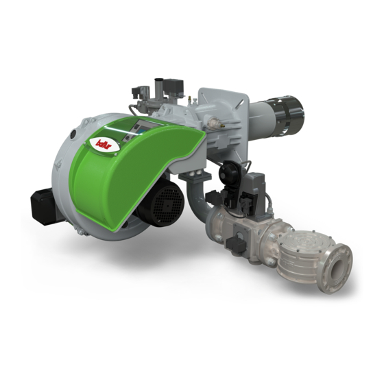
- Page 1 BRUCIATORI GAS BISTADIO PROGRESSIVO / MODULANTE CON CAMMA ELETTRONICA TWO-STAGE PROGRESSIVE / MODULATING GAS BURNERS WITH ELECTRONIC CAM ITALIANO TBG 320SLX ME Manuale istruzioni per l'installazione, l'uso e la manutenzione 18440010 Instruction manual for TBG 480SLX ME installation, use and maintenance...
-
Page 3: Table Of Contents
ITALIANO ITALIANO SOMMARIO Avvertenze per l'uso in condizioni di sicurezza ..............................2 Caratteristiche tecniche ......................................6 Materiale a corredo ......................................6 Targa identificazione bruciatore..................................7 Dati registrazione prima accensione ................................7 Caratteristiche costruttive ....................................8 Caratteristiche tecnico funzionali ..................................8 Campo di lavoro .......................................8 Descrizione componenti ....................................9 Quadro elettrico ........................................9 Descrizione componenti ....................................10 Quadro elettrico ......................................10... -
Page 4: Avvertenze Per L'uso In Condizioni Di Sicurezza
ITALIANO AVVERTENZE PER L'USO IN CONDIZIONI DI • Se il bruciatore deve essere utilizzato all'interno di un impianto/ processo, si prega di contattare gli uffici commerciali Baltur. SICUREZZA • La data di produzione dell'apparecchio (mese, anno) sono indicati sulla targa identificazione bruciatore presente sull'apparecchio. - Page 5 • L’eventuale riparazione dei prodotti dovrà essere effettuata • Prima di avviare il bruciatore e almeno una volta all’anno, far solamente da un centro di assistenza autorizzato da BALTUR o dal effettuare da personale professionalmente qualificato le seguenti suo distributore locale, utilizzando esclusivamente ricambi originali.
- Page 6 ITALIANO AVVERTENZE PARTICOLARI PER L’USO DEL GAS. (pioggia, sole, ecc.) a meno che non sia espressamente previsto; • Verificare che la linea di adduzione e la rampa siano conformi alle - non permettere che l’apparecchio sia usato da bambini o da norme e prescrizioni vigenti.
- Page 7 ITALIANO A CURA DELL'INSTALLATORE prevedere una lunghezza maggiore del conduttore di terra in modo • Installare un idoneo sezionatore per ciascuna linea di alimentazione da garantire che non sia soggetto in alcun modo alla disconnessione del bruciatore seguendo le caratteristiche e lo schema riportato nel accidentale in seguito alle possibili sollecitazioni meccaniche.
-
Page 8: Caratteristiche Tecniche
ITALIANO CARATTERISTICHE TECNICHE MODELLO TBG 320SLX ME TBG 480SLX ME Potenza termica massima metano 4200 5500 Potenza termica minima metano mg/kWh ¹) emissioni metano Classe 4 Classe 4 Funzionamento Modulazione elettronica Modulazione elettronica Trasformatore metano 50 hz 8kV - 20 mA - 230V 8kV - 20 mA - 230V Stm³/h... -
Page 9: Targa Identificazione Bruciatore
ITALIANO TARGA IDENTIFICAZIONE BRUCIATORE Logo aziendale Ragione sociale azienda Codice prodotto Modello bruciatore Matricola Potenza combustibili liquidi Potenza combustibili gassosi Pressione combustibili gassosi Viscosità combustibili liquidi Potenza motore ventilatore Tensione di alimentazione Grado di protezione Paese di costruzione e numeri di certificato di omologazione Data di produzione mese / anno Codice a barre matricola bruciatore DATI REGISTRAZIONE PRIMA ACCENSIONE... -
Page 10: Caratteristiche Costruttive
• Apparecchiatura automatica di comando e controllo del bruciatore con microprocessore secondo normativa europea EN298 integrata con controllo tenuta valvole. • Impianto elettrico con grado di protezione IP54. CAMPO DI LAVORO mbar / hPa TBG 480SLX ME TBG 320SLX ME 1000 2000 3000 4000 5000 6000 IMPORTANTE I campi di lavoro sono ottenuti su caldaie di prova rispondenti alla norma EN676 e sono orientativi per gli accoppiamenti bruciatore-caldaia. -
Page 11: Descrizione Componenti
ITALIANO DESCRIZIONE COMPONENTI TBG 320 SLX ME Testa di combustione Guarnizione Flangia attacco bruciatore Dispositivo regolazione testa Servomotore regolazione aria Sinottico Quadro elettrico Gruppo serrande aria Cerniera Motore ventola Convogliatore aria in aspirazione Presa di pressione gas principale alla testa di combustione Servomotore regolazione gas principale Servomotore regolazione gas secondario Targa identificazione bruciatore... -
Page 12: Descrizione Componenti
ITALIANO DESCRIZIONE COMPONENTI TBG 480 SLX ME Testa di combustione Guarnizione Flangia attacco bruciatore Dispositivo regolazione testa Servomotore regolazione aria Sinottico Quadro elettrico Gruppo serrande aria Cerniera Motore ventola Convogliatore aria in aspirazione Presa di pressione gas principale alla testa di combustione Servomotore regolazione gas principale Servomotore regolazione gas secondario Targa identificazione bruciatore... -
Page 13: Dimensioni Di Ingombro
ITALIANO DIMENSIONI DI INGOMBRO Ø G Modello E Ø F Ø TBG 320SLX ME 1060 1820 TBG 480SLX ME 1110 1840 Modello LØ N Ø TBG 320SLX ME DN80 3/4" 520 ÷ 600 TBG 480SLX ME DN80 3/4" 520 ÷ 600... -
Page 14: Applicazione Del Bruciatore Alla Caldaia
ITALIANO APPLICAZIONE DEL BRUCIATORE ALLA CALDAIA Per la movimentazione del bruciatore, utilizzare catene o funi certificate e adeguate al peso del bruciatore utilizzando i punti di ancoraggio (21). MONTAGGIO GRUPPO TESTA La testa di combustione viene imballata separatamente dal corpo ventilante. - Page 15 ITALIANO MONTAGGIO RAMPA GAS La rampa gas è omologata secondo normativa EN 676 e viene fornita separatamente. Per questa gamma di bruciatori la rampa è personalizzata, composta da una rampa principale (5) e una secondaria (2). Montare la rampa come segue: •...
- Page 16 ITALIANO MONTAGGIO CORPO VENTILANTE Per la movimentazione del bruciatore, utilizzare catene o funi certificate e adeguate al peso del bruciatore utilizzando i punti di ancoraggio (21). • Il bruciatore è predisposto di cerniera ad apertura ambidestra per un comodo accesso alla testa di combustione con bruciatore montato. Dopo aver installato il gruppo testa sulla caldaia, posizionare il corpo ventilante (2) e le relative rondelle (5) in corrispondenza delle cerniere (22).
-
Page 17: Linea Di Alimentazione
ITALIANO LINEA DI ALIMENTAZIONE Lo schema di principio della linea di alimentazione gas è riportato nella figura sotto. La rampa gas è omologata secondo normativa EN 676 e viene fornita separatamente dal bruciatore. Per ottenere il miglior funzionamento del regolatore di pressione è opportuno che sia applicato sulla tubazione orizzontale dopo il filtro. -
Page 18: Collegamenti Elettrici
ITALIANO COLLEGAMENTI ELETTRICI • Tutti i collegamenti devono essere eseguiti con filo elettrico flessibile. • Le sezioni dei conduttori non specificati sono da considerarsi di 0,75 mm². • Le linee elettriche devono essere distanziate dalle parti calde. • L’installazione del bruciatore è consentita solo in ambienti con grado di inquinamento 2 come indicato nella norma EN 60204-1. - Page 19 ITALIANO PROTEZIONE CON SEZIONATORE, MAGNETOTERMICO E INTERRUTTORE DIFFERENZIALE TABELLA 1 TBG 450 ME TBG 510 ME - 320 SLX ME TBG 650 ME TBG 750 ME Collegamento 3~400V e 1+N ~230V 50 Hz 1~230V 50 3~400V 50 1~230V 50 3~400V 50 1~230V 50 3~400V 50 1~230V 50...
- Page 20 ITALIANO PROTEZIONE CON SEZIONATORE E FUSIBILI TABELLA 2 TBG 450 ME TBG 510 ME - 320 SLX ME TBG 650 ME TBG 750 ME Collegamento 3~400V e 1+N ~230V 50 Hz 1~230V 50 3~400V 50 1~230V 50 3~400V 50 1~230V 50 3~400V 50 1~230V 50 3~400V 50...
- Page 21 ITALIANO ESEMPIO 1: Si riporta, ad esclusivo titolo di esempio, il calcolo della massima impedenza dell’anello di guasto ammessa in un sistema "TN", definita CALCOLO DELLA MASSIMA IMPEDENZA DELL’ANELLO DI la taglia, la marca e il modello del fusibile di protezione. GUASTO Utilizzare la documentazione che riporta le curve di intervento relative alla marca e al modello del fusibile utilizzato per la protezione, avente...
- Page 22 ITALIANO ESEMPIO 2: Si riporta, ad esclusivo titolo di esempio, il calcolo della massima impedenza dell’anello di guasto ammessa in un sistema "TT", definita CALCOLO DELLA MASSIMA IMPEDENZA DELL’ANELLO DI la taglia, la marca e il modello del fusibile di protezione. GUASTO Utilizzare la documentazione che riporta le curve di intervento relative alla marca e al modello del fusibile utilizzato per la protezione, avente...
-
Page 23: Descrizione Del Funzionamento
ITALIANO DESCRIZIONE DEL FUNZIONAMENTO bruciatore viene arrestato. Riabbassandosi, la temperatura o pressione al di sotto del valore di I bruciatori ad aria soffiata con modulazione elettronica sono adatti per intervento del dispositivo di controllo, il bruciatore viene nuovamente funzionare su focolari in forte pressione o in depressione secondo le avviato secondo il programma precedentemente descritto. -
Page 24: Accensione E Regolazione
ITALIANO ACCENSIONE E REGOLAZIONE (l'intervento deve arrestare il bruciatore). • Verificare che la tensione della linea elettrica corrisponda a quella richiesta dal costruttore e, che tutti i collegamenti elettrici realizzati sul posto, siano eseguiti come da nostro schema elettrico. • Verificare che lo scarico dei prodotti della combustione attraverso le serrande caldaia e serrande camino, possa avvenire liberamente. -
Page 25: Regolazione Pressione Gas
ITALIANO REGOLAZIONE PRESSIONE GAS Il bruciatore è dotato di due servomotori che regolano in modo indipendente il gas della rampa principale e secondaria (B1, B2). Per una regolazione preliminare della curva di modulazione, si consiglia di regolare la farfalla del gas secondario (B2) più aperta della farfalla gas principale (B1). - Page 26 ITALIANO TBG 320 SLX ME PERDITE IN TESTA POTENZA - PRESSIONE GAS PRINCIPALE mbar/hPa 1000 1500 2000 2500 3000 3500 4000 4500 POTENZA - PRESSIONE GAS SECONDARIO mbar/hPa 1000 1500 2000 2500 3000 3500 4000 4500 24 / 48 0006160489_202211...
- Page 27 ITALIANO TBG 480 SLX ME PERDITE IN TESTA POTENZA - PRESSIONE GAS PRINCIPALE mbar/hPa 1000 2000 3000 4000 5000 6000 POTENZA - PRESSIONE GAS SECONDARIO mbar/hPa 1000 2000 3000 4000 5000 6000 25 / 48 0006160489_202211...
- Page 28 ITALIANO PRESSOSTATO ARIA Il pressostato aria ha lo scopo di mettere in sicurezza (blocco) l’apparecchiatura se la pressione dell’aria non è quella prevista. Il pressostato deve quindi essere regolato per intervenire chiudendo il contatto NO (normalmente aperto) quando la pressione dell’aria nel bruciatore raggiunge il valore a cui è...
-
Page 29: Misurazione Della Corrente Di Ionizzazione
ITALIANO PRESSOSTATI DI CONTROLLO DELLA PRESSIONE DEL GAS MISURAZIONE DELLA CORRENTE DI IONIZZAZIONE I pressostati di controllo della pressione del gas (minima e massima) Il valore minimo della corrente di ionizzazione necessario a far hanno lo scopo di impedire il funzionamento del bruciatore quando la funzionare l'apparecchiatura, è... -
Page 30: Schema Di Regolazione Testa Di Combustione E Distanza Disco Elettrodi
ITALIANO SCHEMA DI REGOLAZIONE TESTA DI COMBUSTIONE E DISTANZA DISCO ELETTRODI TBG 320 SLX ME Elettrodo ionizzazione E (default) E (min) E (max) Elettrodo accensione TBG 320 SLX ME Disco fiamma É possibile regolare gli ugelli gas secondari (6) rispetto alla misura indicata di +/- 20 mm: Miscelatore + 20 mm abbassa leggermente il valore di NOx ma diminuisce la stabilità. - Page 31 ITALIANO SCHEMA DI REGOLAZIONE TESTA DI COMBUSTIONE E DISTANZA DISCO ELETTRODI TBG 480 SLX ME Elettrodo ionizzazione E (default) E (min) E (max) Elettrodo accensione TBG 480 SLX ME Disco fiamma É possibile regolare gli ugelli gas secondari (6) rispetto alla misura indicata di + 20 mm: Miscelatore + 20 mm abbassa leggermente il valore di NOx ma diminuisce la stabilità.
-
Page 32: Manutenzione
ITALIANO MANUTENZIONE Effettuare almeno una volta all’anno e comunque in conformità alle norme vigenti, l’analisi dei gas di scarico della combustione verificando la correttezza dei valori di emissioni. • Pulire le serrande aria, il pressostato aria con presa di pressione ed il relativo tubo se presenti. - Page 33 ITALIANO • Avvitare il manicotto (9) facendolo scorrere all’interno del raccordo mandata gas (11). • Rimuovere la guarnizione (10). • Sollevare leggermente il raccordo mandata gas (11), e sfilare l'intero gruppo miscelazione nella direzione indicata dalla freccia. • Completate le operazioni di manutenzione, procedere a ritroso con il rimontaggio della testa di combustione e verificare la corretta posizione degli elettrodi di accensione e di ionizzazione.
-
Page 34: Tempi Di Manutenzione
ITALIANO TEMPI DI MANUTENZIONE Descrizione particolare Azione da eseguire TESTA DI COMBUSTIONE CONTROLLO VISIVO, INTEGRITA' CERAMICHE, SMERIGLIATURA ESTREMITA', VERIFICARE DISTANZA, ELETTRODI ANNO VERIFICARE CONNESSIONE ELETTRICA DISCO FIAMMA CONTROLLO VISIVO INTEGRITA' EVENTUALI DEFORMAZIONI, PULIZIA ANNO CONTROLLO VISIVO, INTEGRITA' CERAMICHE, SMERIGLIATURA ESTREMITA', VERIFICARE DISTANZA, SONDA DI IONIZZAZIONE ANNO VERIFICARE CONNESSIONE ELETTRICA... -
Page 35: Vita Attesa
ITALIANO VITA ATTESA La vita attesa dei bruciatori e dei relativi componenti dipende molto dal tipo di applicazione su cui il bruciatore è installato, dai cicli, dalla potenza erogata, dalle condizioni dell’ambiente in cui si trova, dalla frequenza e modalità di manutenzione, ecc. ecc. Le normative relative ai componenti di sicurezza prevedono una vita attesa di progetto espressa in cicli e/o anni di funzionamento. -
Page 36: Istruzioni Per L'accertamento Delle Cause Di Irregolarità Nel Funzionamento E La Loro Eliminazione
ITALIANO ISTRUZIONI PER L'ACCERTAMENTO DELLE CAUSE DI IRREGOLARITÀ NEL FUNZIONAMENTO E LA LORO ELIMINAZIONE IRREGOLARITÁ POSSIBILE CAUSA RIMEDIO Invertire l'alimentazione (lato 230V) del trasformatore di accensione e verificare con Disturbo della corrente di ionizzazione da micro-amperometro analogico. parte del trasformatore di accensione. Sostituire il sensore fiamma. -
Page 37: Schemi Elettrici
ITALIANO SCHEMI ELETTRICI TBG 320 SLX ME 35 / 48 0006160489_202211... - Page 38 ITALIANO TBG 320 SLX ME 36 / 48 0006160489_202211...
- Page 39 ITALIANO TBG 320 SLX ME 37 / 48 0006160489_202211...
- Page 40 ITALIANO TBG 320 SLX ME 38 / 48 0006160489_202211...
- Page 41 ITALIANO TBG 320 SLX ME 39 / 48 0006160489_202211...
- Page 42 ITALIANO TBG 320 SLX ME 40 / 48 0006160489_202211...
- Page 43 ITALIANO TBG 480SLX ME 18460010 41 / 48 0006160489_202211...
- Page 44 ITALIANO TBG 480SLX ME 18460010 42 / 48 0006160489_202211...
- Page 45 ITALIANO TBG 480SLX ME 18460010 43 / 48 0006160489_202211...
- Page 46 ITALIANO TBG 480SLX ME 18460010 44 / 48 0006160489_202211...
- Page 47 ITALIANO TBG 480SLX ME 18460010 45 / 48 0006160489_202211...
- Page 48 ITALIANO TBG 480SLX ME 18460010 46 / 48 0006160489_202211...
- Page 49 ITALIANO APPARECCHIATURA Colore serie fili GNYE VERDE / GIALLO SENSORE FIAMMA SONDA ATTIVA GRIGIO SONDA DI PRESSIONE BRUNO SONDA DI TEMPERATURA NERO SONDA DI TEMPERATURA ACQUA CONNETTORE NERO CON SOVRASTAMPA SONDA DI TEMPERATURA ESTERNA ** Solo per taratura RELE’ TERMICO FU1÷4 FUSIBILI CAUTELA / AVVERTENZE SPIA BLOCCO ESTERNA / LAMPADA FUNZIONAMENTO...
- Page 50 ITALIANO 48 / 48 0006160489_202211...
- Page 51 ENGLISH ENGLISH SUMMARY Warnings for use in safety conditions ..................................2 Technical specifications ......................................6 Standard accessories .......................................6 Burner identification plate ....................................7 Data recorded during first start-up ..................................7 Design characteristics ......................................8 Technical functional characteristics ..................................8 Operating range .......................................8 Component description ....................................9 Electrical panel .........................................9 Component description ....................................10 Electrical panel .......................................10 Overall dimensions ......................................
-
Page 52: Warnings For Use In Safety Conditions
• If the burner is to be used inside a system/process, please contact the sales offices Baltur. • The equipment production date (month, year) is written on the burner identification plate located on the equipment. - Page 53 Contact only qualified personnel. - At the end of the adjustment procedures, check that all the • Any product repairs must only be carried out by BALTUR authorised locking devices of mechanical securing systems are properly assistance centres or by its local distributor using only original spare tightened.
- Page 54 ENGLISH SPECIAL PRECAUTIONS WHEN USING GAS. - The power supply cable for the equipment must not be replaced • Check that the feed line and the train comply with current law and by the user. If the cable is damaged, turn the equipment off and regulations.
- Page 55 ENGLISH TO BE CARRIED OUT BY THE INSTALLER supply lines ensures a “safe” transition in the shortest time possible. • Install a suitable circuit breaker for each power supply line of the • The emergency stop will have to be performed complying with the burner, according to the characteristics and the diagram on the following requirements: chapter ELECTRICAL CONNECTIONS.
-
Page 56: Technical Specifications
ENGLISH TECHNICAL SPECIFICATIONS MODEL TBG 320SLX ME TBG 480SLX ME Maximum natural gas heat power 4200 5500 Minimum natural gas heat power mg/kWh ¹) natural gas emissions Class 4 Class 4 Operation Electronic modulation Electronic modulation 50 Hz natural gas transformer... -
Page 57: Burner Identification Plate
ENGLISH BURNER IDENTIFICATION PLATE Company logo Company name Product code Burner model Serial number Liquid fuel power Gaseous fuel power Gaseous fuel pressure Liquid fuel viscosity Fan motor power Power supply voltage Protection rating Country of origin and numbers of certificate of approval Manufacturing date - month / year Bar code serial number of burner DATA RECORDED DURING FIRST START-UP... -
Page 58: Design Characteristics
• Automatic burner command and control equipment with microprocessor in compliance with European standard EN298 integrated with valve seal control. • Electrical system with protection rating IP54. OPERATING RANGE mbar / hPa TBG 480SLX ME TBG 320SLX ME 1000 2000 3000 4000 5000 6000 IMPORTANT The operating ranges are obtained from test boilers corresponding to Standard EN676 and are indicative of the burner-boiler combination. -
Page 59: Component Description
ENGLISH COMPONENT DESCRIPTION TBG 320 SLX ME Combustion head Seal Burner connection flange Combustion head adjustment device Air regulation servomotor Synoptic control panel Electrical panel Air gate unit Hinge Fan motor Intake air conveyor Main gas pressure port to combustion head Main gas regulation servomotor Secondary gas regulation servomotor Burner identification plate... -
Page 60: Component Description
ENGLISH COMPONENT DESCRIPTION TBG 480 SLX ME Combustion head Seal Burner connection flange Combustion head adjustment device Air regulation servomotor Synoptic control panel Electrical panel Air gate unit Hinge Fan motor Intake air conveyor Main gas pressure port to combustion head Main gas regulation servomotor Secondary gas regulation servomotor Burner identification plate... -
Page 61: Overall Dimensions
ENGLISH OVERALL DIMENSIONS Ø G Model E Ø F Ø TBG 320SLX ME 1060 1820 TBG 480SLX ME 1110 1840 Model LØ N Ø TBG 320SLX ME DN80 3/4" 520 ÷ 600 TBG 480SLX ME DN80 3/4" 520 ÷ 600... -
Page 62: Burner Connection To The Boiler
ENGLISH BURNER CONNECTION TO THE BOILER For burner handling, use certified chains or ropes suitable for the burner weight using the anchoring points (21). HEAD UNIT ASSEMBLY The combustion head is packaged separately from the body of the burner. Anchor the head unit to the boiler door as follows: •... - Page 63 ENGLISH ASSEMBLING THE GAS TRAIN The EN 676 approved gas train is sold separately from the burner. For this range of burners the train is customised, consisting of a main train (5) and a secondary train (2). Fit the train as follows: •...
- Page 64 ENGLISH ASSEMBLY OF VENTILATION SYSTEM For burner handling, use certified chains or ropes suitable for the burner weight using the anchoring points (21). • The burner has an ambidextrous hinge opening for easy access to the combustion head with fitted burner. After having installed the head unit on boiler, position the ventilating body (2) and relevant washers (5) close to hinges (22).
-
Page 65: Supply Line
ENGLISH SUPPLY LINE The figure below shows the gas supply line block diagram. The gas train is certified in compliance with EN 676 Standard and supplied separately from the burner. To ensure optimal functioning of the pressure regulator, it should be applied to the horizontal pipe after the filter. -
Page 66: Electrical Connections
ENGLISH ELECTRICAL CONNECTIONS • It is advisable to make all connections with flexible electric wire. • Conductor cross-sections not specified are to be considered as 0,75 mm². • The power lines must be distanced from the hot parts. • The burner can be installed exclusively in environments with pollution degree 2 as specified in Standard EN 60204-1. - Page 67 ENGLISH PROTECTION WITH DISCONNECTING SWITCH, CIRCUIT BREAKER AND DIFFERENTIAL SWITCH TABLE 1 TBG 450 ME TBG 510 ME - 320 SLX ME TBG 650 ME TBG 750 ME Connection 3~400V and 1+N ~230V 50 Hz 1~230V 50 3~400V 50 1~230V 50 3~400V 50 1~230V 50 3~400V 50...
- Page 68 ENGLISH PROTECTION WITH DISCONNECTING SWITCH AND FUSES TABLE 2 TBG 450 ME TBG 510 ME - 320 SLX ME TBG 650 ME TBG 750 ME Connection 3~400V and 1+N ~230V 50 Hz 1~230V 50 3~400V 50 1~230V 50 3~400V 50 1~230V 50 3~400V 50 1~230V 50...
- Page 69 ENGLISH EXAMPLE NO. 1: Only by way of example, find below the calculation of the maximum fault loop impedance allowed in a "TN" system, with the definition of CALCULATION OF THE MAXIMUM FAULT LOOP IMPEDANCE the protection fuse size, brand and model. Use the documentation showing the intervention curves related to the System brand and the model of the fuse used for the protection, having the size...
- Page 70 ENGLISH EXAMPLE NO. 2: Only by way of example, find below the calculation of the maximum fault loop impedance allowed in a "TT" system, with the definition of CALCULATION OF THE MAXIMUM FAULT LOOP IMPEDANCE the protection fuse size, brand and model. Use the documentation showing the intervention curves related to the System brand and the model of the fuse used for the protection, having the size...
-
Page 71: Operating Description
ENGLISH OPERATING DESCRIPTION adjusts the fuel and combustion air flow rate through the relevant servomotors. Blown air burners with electronic modulation may be used on hearths • in a clockwise direction the air flow increases; under strong pressure or in a vacuum, according to the corresponding •... -
Page 72: Starting Up And Regulation
ENGLISH STARTING UP AND REGULATION • Make sure that the mains voltage corresponds to the manufacturer's requirements and that all electrical connections made at the installation site are effected properly as illustrated in our wiring diagram. • Make sure that the combustion products may be freely vented through the boiler and flue dampers. -
Page 73: Gas Pressure Regulation
ENGLISH GAS PRESSURE REGULATION The burner is equipped with two servomotors that independently regulate the main and secondary train gas (B1, B2). For a preliminary regulation of the modulation curve, it is recommended to set the secondary gas butterfly (B2) more open than the main gas butterfly (B1). - Page 74 ENGLISH TBG 320 SLX ME HEAD LOSSES POWER - MAIN GAS PRESSURE mbar/hPa 1000 1500 2000 2500 3000 3500 4000 4500 POWER - SECONDARY GAS PRESSURE mbar/hPa 1000 1500 2000 2500 3000 3500 4000 4500 24 / 48 0006160489_202211...
- Page 75 ENGLISH TBG 480 SLX ME HEAD LOSSES POWER - MAIN GAS PRESSURE mbar/hPa 1000 2000 3000 4000 5000 6000 POWER - SECONDARY GAS PRESSURE mbar/hPa 1000 2000 3000 4000 5000 6000 25 / 48 0006160489_202211...
- Page 76 ENGLISH AIR PRESSURE SWITCH The air pressure switch stops the equipment operation if air pressure is not at the expected value. The pressure switch must therefore be adjusted so that it is triggered to close the NO (normally open) contact when the air pressure in the burner reaches the set value.
-
Page 77: Ionisation Current Measurement
ENGLISH GAS CONTROL PRESSURE SWITCHES IONISATION CURRENT MEASUREMENT The gas pressure control switches (minimum and maximum) prevent The maximum ionisation current value required for a correct operation the burner from operating when gas pressure does not lie between the of the equipment is indicated in the wiring diagram. expected range. -
Page 78: Diagram For Regulating The Combustion Head And The Electrode Disk Distance
ENGLISH DIAGRAM FOR REGULATING THE COMBUSTION HEAD AND THE ELECTRODE DISK DISTANCE TBG 320 SLX ME Ionisation electrode E (default) E (min) E (max) Ignition electrode TBG 320 SLX ME Flame disc It is possible to adjust the gas secondary nozzles (6) to the indicated size of +/- 20 mm: Mixer + 20 mm NOx value is slightly lowered but stability is decreased. - Page 79 ENGLISH DIAGRAM FOR REGULATING THE COMBUSTION HEAD AND THE ELECTRODE DISK DISTANCE TBG 480 SLX ME Ionisation electrode Ignition electrode E (default) E (min) E (max) TBG 480 SLX ME Flame disc Mixer It is possible to adjust the gas secondary nozzles (6) to the indicated size of + 20 mm: Internal diffuser + 20 mm NOx value is slightly lowered but stability is decreased.
-
Page 80: Maintenance
ENGLISH MAINTENANCE Analyse combustion gases and check that the emission values are correct at least once a year, in compliance with current law. • Clean air dampers, the air pressure switch with pressure port and the relevant pipe, if any. •... - Page 81 ENGLISH • Screw the sleeve (9) by sliding it into the gas supply connection (11). • Remove gasket (10). • Slightly raise the gas delivery connection (11), and remove the entire mixing unit in the direction indicated by the arrow. •...
-
Page 82: Maintenance Time
ENGLISH MAINTENANCE TIME Part description Action to be performed COMBUSTION HEAD VISUAL INSPECTION OF THE INTEGRITY OF CERAMICS. TIP GRINDING, CHECK DISTANCE, CHECK ELECTRODES YEAR ELECTRICAL CONNECTION FLAME DISC INTEGRITY VISUAL CHECK FOR ANY DEFORMATIONS, CLEANING, YEAR VISUAL INSPECTION OF THE INTEGRITY OF CERAMICS. TIP GRINDING, CHECK DISTANCE, CHECK IONISATION PROBE YEAR ELECTRICAL CONNECTION... -
Page 83: Expected Lifespan
ENGLISH EXPECTED LIFESPAN The expected lifespan of burners and relevant components depends very much from the type of application on which the burner is installed, from cycles ,of delivered power, from the conditions of the environment in which it is located, from maintenance frequency and mode, etc. Standards about safety components provide for a project expected lifespan expressed in cycles and/or years of operation. -
Page 84: Instructions For Determining The Cause Leading To Irregularities In The Operation And Their Elimination
ENGLISH INSTRUCTIONS FOR DETERMINING THE CAUSE LEADING TO IRREGULARITIES IN THE OPERATION AND THEIR ELIMINATION IRREGULARITY POSSIBLE CAUSE REMEDY Invert the ignition transformer power supply (230V side) and check using an analogue Disturbance to ionization current from the micro-ammeter. ignition transformer. Replace the flame sensor. -
Page 85: Wiring Diagrams
ENGLISH WIRING DIAGRAMS TBG 320 SLX ME 35 / 48 0006160489_202211... - Page 86 ENGLISH TBG 320 SLX ME 36 / 48 0006160489_202211...
- Page 87 ENGLISH TBG 320 SLX ME 37 / 48 0006160489_202211...
- Page 88 ENGLISH TBG 320 SLX ME 38 / 48 0006160489_202211...
- Page 89 ENGLISH TBG 320 SLX ME 39 / 48 0006160489_202211...
- Page 90 ENGLISH TBG 320 SLX ME 40 / 48 0006160489_202211...
- Page 91 ENGLISH TBG 480SLX ME 18460010 41 / 48 0006160489_202211...
- Page 92 ENGLISH TBG 480SLX ME 18460010 42 / 48 0006160489_202211...
- Page 93 ENGLISH TBG 480SLX ME 18460010 43 / 48 0006160489_202211...
- Page 94 ENGLISH TBG 480SLX ME 18460010 44 / 48 0006160489_202211...
- Page 95 ENGLISH TBG 480SLX ME 18460010 45 / 48 0006160489_202211...
- Page 96 ENGLISH TBG 480SLX ME 18460010 46 / 48 0006160489_202211...
- Page 97 ENGLISH CONTROL BOX Wire series colour GNYE GREEN / YELLOW Flame sensor BLUE ACTIVE PROBE GREY PRESSURE PROBE BROWN TEMPERATURE PROBE BLACK WATER TEMPERATURE PROBE BLACK CONNECTOR WITH OVERPRINT EXTERNAL TEMPERATURE PROBE ** For calibration only THERMAL RELAY FU1÷4 FUSES CAUTION / WARNINGS EXTERNAL LOCK INDICATOR LIGHT/ AUXILIARY HEATING For the dimensioning of sections S1, S2 and the dimensioning...
- Page 98 ENGLISH 48 / 48 0006160489_202211...
- Page 100 BALTUR S.P.A. Via Ferrarese, 10 44042 Cento (Fe) - Italy Tel. +39 051-6843711 Fax. +39 051-6857527/28 www.baltur.it info@baltur.it Il presente catalogo riveste carattere puramente indicativo. La casa, pertanto, si riserva ogni possibilità di modifica dei dati tecnici e di quant'altro in esso riportato.
Need help?
Do you have a question about the TBG 320SLX ME and is the answer not in the manual?
Questions and answers