baltur TBG 35 ME Installation, Use And Maintenance Instruction Manual
Two-stage progressive/ modulating gas burners
Hide thumbs
Also See for TBG 35 ME:
Table of Contents
Advertisement
Available languages
Available languages
Quick Links
BRUCIATORI GAS BISTADIO PROGRESSIVO / MODULANTE
TWO-STAGE PROGRESSIVE / MODULATING GAS BURNERS
ITALIANO
TBG 35 ME
Manuale istruzioni per l'installazione,
IT
l'uso e la manutenzione
Installation, use and maintenance
EN
instruction manual
ISTRUZIONI ORIGINALI (IT)
ORIGINAL INSTRUCTIONS (IT)
0006160161_201711
Advertisement
Table of Contents

Related Manuals for baltur TBG 35 ME


Summary of Contents for baltur TBG 35 ME
- Page 1 BRUCIATORI GAS BISTADIO PROGRESSIVO / MODULANTE TWO-STAGE PROGRESSIVE / MODULATING GAS BURNERS ITALIANO TBG 35 ME Manuale istruzioni per l'installazione, l'uso e la manutenzione Installation, use and maintenance instruction manual ISTRUZIONI ORIGINALI (IT) ORIGINAL INSTRUCTIONS (IT) 0006160161_201711...
-
Page 3: Table Of Contents
ITALIANO ITALIANO SOMMARIO Avvertenze per l'uso in condizioni di sicurezza ..............................3 Caratteristiche tecniche ...................................... 6 Materiale a corredo ...................................... 7 Targa identificazione bruciatore ................................... 7 Dati registrazione prima accensione ................................7 Campo di lavoro ......................................8 Quadro elettrico ......................................8 Dimensioni di ingombro ....................................9 Descrizione componenti .....................................10 Linea di alimentazione .................................... - Page 4 ITALIANO DICHIARAZIONE DI CONFORMITÀ CE0085: DVGW CERT GmbH, Josef-Wirmer Strasse 1-3-53123 Bonn (D) Dichiariamo che i nostri bruciatori ad aria soffiata di combustibili gassosi e misti, serie: BPM...; BGN…; BTG…; TBML...; Comist…; GI…; GI…Mist; Minicomist…; Sparkgas...; TBG..; IB..; TBR... (Variante: … LX, per basse emissioni NOx; -V per inverter, FGR per ricircolazione esterna fumi) rispettano i requisiti minimi imposti dalle Direttive e Regolamenti europei: •...
-
Page 5: Avvertenze Per L'uso In Condizioni Di Sicurezza
ITALIANO AVVERTENZE PER L'USO IN CONDIZIONI DI compresi) le cui capacità fisiche, sensoriali o mentali siano ridotte, oppure con mancanza di esperienza o di conoscenza. SICUREZZA • l'uso dell'apparecchio è consentito a tali persone solo nel caso in cui possano beneficiare, attraverso l'intermediazione di una SCOPO DEL MANUALE persona responsabile, di informazioni relative alla loro sicurezza, Il manuale si propone di contribuire all'utilizzo sicuro del prodotto... - Page 6 • Prima di avviare il bruciatore e almeno una volta all’anno, far • L’eventuale riparazione dei prodotti dovrà essere effettuata effettuare da personale professionalmente qualificato le seguenti solamente da un centro di assistenza autorizzato da BALTUR o dal operazioni: suo distributore locale, utilizzando esclusivamente ricambi originali.
- Page 7 ITALIANO Avvertenze particolari per l’uso del gas. • L’alimentazione elettrica del bruciatore deve prevedere il neutro a • Verificare che la linea di adduzione e la rampa siano conformi alle terra. In caso di controllo della corrente di ionizzazione con neutro norme e prescrizioni vigenti.
-
Page 8: Caratteristiche Tecniche
ITALIANO CARATTERISTICHE TECNICHE MODELLO TBG 35 ME POTENZA TERMICA MASSIMA METANO POTENZA TERMICA MINIMA METANO mg/kWh ¹) EMISSIONI METANO Classe 3 FUNZIONAMENTO Bistadio progressivo modulante TRASFORMATORE METANO 50 Hz 26 kV - 40 mA - 230/240 V TRASFORMATORE METANO 60 Hz 26 kV - 40 mA - 220/230 V Stm³/h... -
Page 9: Materiale A Corredo
ITALIANO MATERIALE A CORREDO MODELLO TBG 35 ME FLANGIA ATTACCO BRUCIATORE GUARNIZIONE ISOLANTE PRIGIONIERI N° 4 M 12 DADI ESAGONALI N° 4 M 12 NIPPLO TARGA IDENTIFICAZIONE BRUCIATORE Logo aziendale Ragione sociale azienda Codice prodotto Modello bruciatore Matricola Potenza combustibili liquidi... -
Page 10: Campo Di Lavoro
ITALIANO CAMPO DI LAVORO mbar TBG 35 P / PN TBG 35 MC / ME /h (Metano) /h (G.P.L.) IMPORTANTE I campi di lavoro sono ottenuti su caldaie di prova rispondenti alla norma EN676 e sono orientativi per gli accoppiamenti bruciatore- caldaia. -
Page 11: Dimensioni Di Ingombro
ITALIANO DIMENSIONI DI INGOMBRO Modello TBG 35 ME Modello E Ø F Ø LØ N Ø TBG 35 ME 140 ÷ 300 200 ÷ 245 9 / 34 0006160161_201711... -
Page 12: Descrizione Componenti
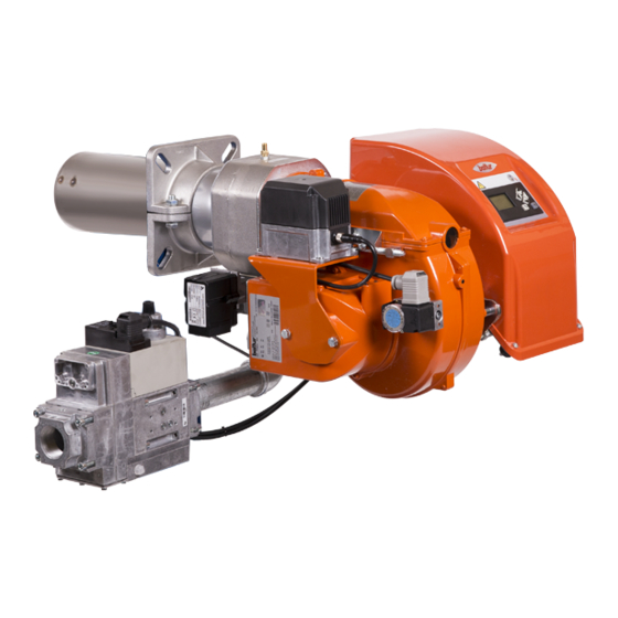
ITALIANO DESCRIZIONE COMPONENTI Testa di combustione Guarnizione Flangia attacco bruciatore Dispositivo regolazione testata Coperchio chiocciola Flangia attacco rampa gas Quadro elettrico Motore Servomotore regolazione aria Servomotore regolazione gas 6 10 Pressostato aria Targa identificazione bruciatore 10 / 34 0006160161_201711... -
Page 13: Linea Di Alimentazione
ITALIANO LINEA DI ALIMENTAZIONE Lo schema di principio della linea di alimentazione gas è riportato nella figura sotto. La rampa gas è omologata secondo normativa EN 676 e viene fornita separatamente dal bruciatore. PERICOLO / ATTENZIONE Occorre installare, a monte della valvola gas, una valvola di intercettazione manuale e un giunto antivibrante, disposti secondo quanto indicato nello schema di principio. -
Page 14: Caratteristiche Tecnico Funzionali
ITALIANO CARATTERISTICHE TECNICO FUNZIONALI CARATTERISTICHE COSTRUTTIVE • Bruciatore di gas conforme alle normative europee EN 676 ed alle I bruciatori risultano composti da: Direttive Europee 2006/42/CE; 2006/95/CE; 97/23/CE; 2004/108/ • Presa d'aria comburente con serranda a farfalla per la regolazione della portata d'aria. -
Page 15: Applicazione Del Bruciatore Alla Caldaia
ITALIANO APPLICAZIONE DEL BRUCIATORE ALLA CALDAIA MONTAGGIO GRUPPO TESTATA • Posizionare sul canotto la guarnizione isolante (13) interponendo la corda (2) tra la flangia e guarnizione. • Adeguare la posizione della flangia di attacco (19) allentando le viti (6), la testa del bruciatore dovrà penetrare nel focolare della misura consigliata dal costruttore del generatore. -
Page 16: Predisposizione Per Attacco Rampa Verso L'alto
ITALIANO PREDISPOSIZIONE PER ATTACCO RAMPA VERSO L'ALTO Se si desidera portare il lato di ingresso rampa verso l'alto, prima di applicare il bruciatore alla caldaia, seguire la procedura seguente: • Seguendo le istruzioni riportate al paragrafo " Manutenzione", estrarre il gruppo miscelazione e togliere la vite (8) che collega l'asta di avanzamento (14) del gruppo con il tubo mandata gas (15).Togliere la vite (16) che collega il miscelatore gas (17) al tubo. -
Page 17: Collegamenti Elettrici
ITALIANO COLLEGAMENTI ELETTRICI • Tutti i collegamenti devono essere eseguiti con filo elettrico flessibile. • Rispettare le normative nazionali ed europee applicabili (es. EN 60335-1/EN 50165) relative alla sicurezza elettrica; • Le linee elettriche devono essere distanziate dalle parti calde. •... - Page 18 ITALIANO • Avvitare le viti (6) esercitando una coppia di serraggio adeguata ad assicurare la corretta tenuta, per richiudere il coperchio del quadro eletttrico. CAUTELA / AVVERTENZE L’apertura del quadro elettrico del bruciatore è consentita esclusivamente a personale professionalmente qualificato. Il motore elettrico è...
-
Page 19: Descrizione Del Funzionamento Adue Stadi Progressivi
ITALIANO DESCRIZIONE DEL FUNZIONAMENTO A CAUTELA / AVVERTENZE DUE STADI PROGRESSIVI La camma elettronica comanda il bruciatore, azionando il servomotore dell'aria comburente, del gas e, se presente I bruciatori ad aria soffiata con modulazione elettronica sono adatti l'inverter del motore ventola, secondo una curva di lavoro per funzionare su focolari in forte pressione o in depressione secondo avente dieci punti impostati (vedi tabella regolazione curva). - Page 20 ITALIANO Nel normale funzionamento la sonda di modulazione applicata alla caldaia rileva le variazioni di richiesta ed automaticamente provvede ad adeguare l'erogazione di combustibile e di aria comburente inserendo i servomotori di regolazione dell'erogazione (aria/gas) modulando l'erogazione. Con questa manovra il sistema di regolazione dell'erogazione (aria/ gas) cerca di equilibrare la quantità...
-
Page 21: Accensione E Regolazione Gas Metano
ITALIANO ACCENSIONE E REGOLAZIONE GAS • Verificare ora il corretto funzionamento automatico della modulazione. In questo modo l'apparecchiatura riceve il segnale METANO dal regolatore elettronico di modulazione se il bruciatore è in versione modulante, oppure dal termostato o pressostato del •... -
Page 22: Corrente Ionizzazione
ITALIANO • Verificare il funzionamento del rilevatore di fiamma come segue: - staccare il cavo proveniente dall'elettrodo di ionizzazione; - avviare il bruciatore; - l'apparecchiaura completerà il ciclo di controllo e dopo due secondi manderà in blocco il bruciatore per mancata fiamma di accensione;... -
Page 23: Regolazione Aria Sulla Testa Di Combustione
Controllare che l'accensione avvenga regolarmente, se l'apertura della testa è eccessiva, si potrebbe verificare forte turbolenza d'aria e quindi difficoltà d'accensione. Modello Valore indice (4) TBG 35 ME 3 ÷ 31 0 ÷ 6 X = Distanza testa-disco; regolare la distanza X seguendo le indicazioni: •... -
Page 24: Schema Di Regolazione Distanza Disco Elettrodi
ITALIANO SCHEMA DI REGOLAZIONE DISTANZA DISCO ELETTRODI TBG 35 1 - Elettrodo ionizzazione 2 - Elettrodo accensione TBG 35 ME 3 - Disco fiamma 4 - Miscelatore 5 - Tubo mandata gas TBG 35 ME E - ATTENZIONE: uscita foro ugello centrale in prossimità della punta dell'elettrodo. -
Page 25: Manutenzione
ITALIANO MANUTENZIONE Effettuare almeno una volta all’anno e comunque in conformità alle norme vigenti, l’analisi dei gas di scarico della combustione verificando la correttezza dei valori di emissioni. • Controllare che il filtro del combustibile sia pulito. Se necessario sostituirlo. •... -
Page 26: Tempi Di Manutenzione
ITALIANO TEMPI DI MANUTENZIONE Descrizione particolare Azione da eseguire TESTA DI COMBUSTIONE CONTROLLO VISIVO, INTEGRITA CERAMICHE. SMERIGLIATURA ESTREMITA, VERIFICARE ELETTRODI ANNUO DISTANZA, VERIFICARE CONNESSIONE ELETTRICA DISCO FIAMMA CONTROLLO VISIVO INTEGRITA EVENTUALI DEFORMAZIONI, PULIZIA ANNUO CONTROLLO VISIVO, INTEGRITA CERAMICHE. SMERIGLIATURA ESTREMITA, VERIFICARE SONDA DI IONIZZAZIONE ANNUO DISTANZA, VERIFICARE CONNESSIONE ELETTRICA... -
Page 27: Vita Attesa
ITALIANO VITA ATTESA La vita attesa dei bruciatori e dei relativi componenti dipende molto dal tipo di applicazione su cui il bruciatore è installato, dai cicli della potenza erogata, dalle condizioni dell’ambiente in cui si trova, dalla frequenza e modalità di manutenzione, ecc. ecc. Le normative relative ai componenti di sicurezza, prevedono una vita attesa di progetto espressa in cicli e/o anni di funzionamento. -
Page 28: Precisazioni Sull'uso Del Propano
ITALIANO PRECISAZIONI SULL'USO DEL PROPANO PERICOLO / ATTENZIONE La potenza massima e minima (kW) del bruciatore, è considerata • Valutazione, indicativa, del costo di esercizio; con combustibile metano che coincide approssimativamente - 1 m3 di gas liquido in fase gassosa ha un potere calorifico con quella del propano. -
Page 29: Schema Di Principio Per Riduzione Pressione G.p.l. A Due Stadi Per Bruciatore Oppure Caldaia
ITALIANO SCHEMA DI PRINCIPIO PER RIDUZIONE PRESSIONE G.P.L. A DUE STADI PER BRUCIATORE OPPURE CALDAIA Manometro e presa di pressione Riduttore di 1° salto Riduttore di 2° salto Uscita ~ 1,5 bar Uscita ~ 30 hPa (mbar) Portata ~ il doppio del massimo richiesto Portata ~ il doppio del massimo richiesto dall’utilizzatore dall’utilizzatore... -
Page 30: Istruzioni Montaggio Riduzioni Per Gpl
ITALIANO ISTRUZIONI MONTAGGIO RIDUZIONI PER GPL CAUTELA / AVVERTENZE Nel caso di funzionamento con combustibile GPL inserire le apposite In alcune particolari applicazioni, nel caso si verificassero riduzioni fornite a corredo del bruciatore.Per il montaggio delle pulsazioni di fiamma durante il funzionamento del bruciatore riduzioni seguire le istruzioni sotto riportate. -
Page 31: Istruzioni Per L'accertamento Delle Cause Di Irregolarità Nel Funzionamento E La Loro Eliminazione
ITALIANO ISTRUZIONI PER L'ACCERTAMENTO DELLE CAUSE DI IRREGOLARITÀ NEL FUNZIONAMENTO E LA LORO ELIMINAZIONE IRREGOLARITÁ POSSIBILE CAUSA RIMEDIO Invertire l'alimentazione (lato 230V) del trasformatore di accensione e verificare Disturbo della corrente di ionizzazione con micro-amperometro analogico. da parte del trasformatore di Sostituire il sensore fiamma. -
Page 32: Schemi Elettrici
ITALIANO SCHEMI ELETTRICI 30 / 34 0006160161_201711... - Page 33 ITALIANO 31 / 34 0006160161_201711...
- Page 34 ITALIANO 32 / 34 0006160161_201711...
- Page 35 ITALIANO GNYE VERDE / GIALLO APPARECCHIATURA FOTORESISTENZA / ELETTRODO DI IONIZZAZIONE / FOTOCELLULA UV BRUNO SONDA DI PRESSIONE NERO SONDA DI TEMPERATURA CONNETTORE NERO CON SOVRASTAMPA RELE’ TERMICO FU1÷4 FUSIBILI SPIA BLOCCO ESTERNA / LAMPADA FUNZIONAMENTO RESISTENZE AUSILIARIE CONTATTORE MOTORE VENTOLA CONTATTORE ESTERNO MOTORE VENTOLA Corrente ionizzazione minima 1,4 µA...
- Page 37 ENGLISH ENGLISH INDEX Instructions for use in safe conditions ................................3 Technical specifications ...................................... 6 Supplied material ......................................7 Burner identification plate .................................... 7 First start up recording data ..................................7 Operating range ......................................8 Electrical panel ......................................8 Overall dimensions ......................................9 Component description ....................................10 Supply line .........................................
- Page 38 ENGLISH DECLARATION OF CONFORMITY CE0085: DVGW CERT GmbH, Josef-Wirmer Strasse 1-3-53123 Bonn (D) We hereby declare under our own responsibility, that our blown air burners fired by gas and dual fuel, series: BPM...; BGN…; BTG…; TBML...; Comist…; GI…; GI…Mist; Minicomist…; Sparkgas...; TBG..; IB..; TBR... (Variant: …...
- Page 39 ENGLISH INSTRUCTIONS FOR USE IN SAFE the device. • This appliance should only be used for the purpose it has been CONDITIONS designed for. Any other use is to be considered improper and therefore dangerous. PURPOSE OF THE MANUAL • The equipment must be installed in accordance with current The manual purpose is to contribute to the safe use of the product, regulations, following the manufacturer’s instructions and by indicating the conduct and behaviour required to prevent alterations...
- Page 40 Contact only qualified personnel. - Check the regulation and safety devices are working properly. • Any product repairs must only be carried out by BALTUR authorised - Check for the correct operation of the combustion products assistance centres or its local retailer using only original spare exhaust duct.
- Page 41 ENGLISH Special instructions for using gas. • The use of any components that use electricity means that certain • Check that the feed line and the train comply with current standards fundamental rules have to followed, including the following: and regulations. - do not touch the equipment with parts of the body that are wet •...
- Page 42 ENGLISH TECHNICAL SPECIFICATIONS MODEL TBG 35 ME MAXIMUM NATURAL GAS HEAT POWER MINIMUM NATURAL GAS HEAT POWER mg/kWh ¹) NATURAL GAS EMISSIONS Class 3 OPERATION Two-stage progressive / modulating NATURAL GAS TRANSFORMER 50 Hz 26 kV - 40 mA - 230/240 V...
- Page 43 ENGLISH SUPPLIED MATERIAL MODEL TBG 35 ME BURNER CONNECTION FLANGE INSULATING SEAL STUD BOLTS N° 4 M 12 HEXAGONAL NUTS N° 4 M 12 NIPPLE BURNER IDENTIFICATION PLATE Company logo Company name Product code Model Serial number Liquid fuel power...
- Page 44 ENGLISH OPERATING RANGE mbar TBG 35 P / PN TBG 35 MC / ME /h (Metano) /h (G.P.L.) IMPORTANT The operating ranges are obtained from test boilers corresponding to Standard EN676 and are indicative of the burner-boiler combination. For correct working of the burner the size of the combustion chamber must correspond to current regulations; if not the manufacturers must be consulted.
- Page 45 ENGLISH OVERALL DIMENSIONS Model TBG 35 ME Model E Ø F Ø LØ N Ø TBG 35 ME 140 ÷ 300 200 ÷ 245 9 / 34 0006160161_201711...
- Page 46 ENGLISH COMPONENT DESCRIPTION Combustion head Seal Burner connection flange Combustion head adjustment device Screw-nut cover Gas train connector flange Electrical panel Motor Air regulation servomotor Gas regulation servomotor 6 10 Air pressure switch Burner identification plate 10 / 34 0006160161_201711...
- Page 47 ENGLISH SUPPLY LINE The basic diagram of the gas supply line is shown in the figure below. The gas train is certified in accordance with Standard EN 676 and is supplied separately from the burner. DANGER / CAUTION Install a manual on/off valve upstream of the gas valve according to the layout shown in the diagram illustrating the gas train principle.
- Page 48 ENGLISH TECHNICAL FUNCTIONAL CHARACTERISTICS DESIGN CHARACTERISTICS • Gas burner compliant with European Standards EN 676 and Burners are composed by: European Directives 006/42/EC; 2006/95/EC; 97/23/EC; 2004/108/ • Comburent air intake with throttle gate for the regulation of the air flow rate. •...
- Page 49 ENGLISH BURNER CONNECTION TO THE BOILER ASSEMBLING THE HEAD UNIT • Position insulating seal -13 on the sleeve, placing rope -2 between the flange and the seal. • Adjust the connection flange -19 position loosening the screws -6. The burner head must penetrate to the extent requested by the generator manufacturer.
- Page 50 ENGLISH PREPARATION FOR TRAIN CONNECTION FACING UPWARD If you wish to turn the train inlet upwards, before applying the burner to the boiler, follow the subsequent procedure. • Following the instructions detailed in the “Maintenance” section, extract the mixer unit and remove the screw -8 which connects the unit’s forward movement rod -14 to the gas delivery pipe -15.Remove the screw -16 which connects the gas mixer -17 to the pipe.
- Page 51 ENGLISH ELECTRICAL CONNECTIONS • It is advisable to make all connections with flexible electric wire. • Observe applicable national and European Standards (e.g. EN 60335-1/EN 50165) regarding electrical safety. • Electrical lines must be kept away from hot parts. • The burner installation is allowed only in environments with pollution degree 2 as indicated in annex M of the EN 60335- 1:2008-07 regulation.
- Page 52 ENGLISH • To close the electric panel lid again, tighten the screws -6 to a suitable torque to ensure the correct seal. CAUTION / WARNING Only professionally qualified personnel is allowed to open the burner electrical panel. The electric motor is equipped with thermal protector with automatic reset that stops the unit in case of overheating.
- Page 53 ENGLISH DESCRIPTION OF PROGRESSIVE TWO- CAUTION / WARNING STAGE OPERATION The electronic cam controls the burner, activating the combustion air, gas servomotor and the fan motor, if the Blown air burners with electronic modulation may be used on hearths inverter is fitted, according to a curve that has ten points set under strong pressure or in a vacuum, according to the corresponding (see curve regulation table).
- Page 54 ENGLISH During normal operation, the modulation probe installed on the boiler measures any variation demands and automatically adjusts the fuel and combustion air flow rate by starting the air/gas flow rate modulation servomotors, modulating the output. This causes the air/gas output control system to balance the amount of heat supplied to the boiler with the amount it gives off during use.
- Page 55 ENGLISH NATURAL GAS IGNITION AND REGULATION • Now check the proper automatic operation of modulation. This ensures that the equipment receives the signal from the electronic • Bleed out the air contained in the gas piping, with due precautions modulation regulator, if the burner is the modulating model, or from and with doors and windows open.
- Page 56 ENGLISH • Verify the flame detector operation as follows: - Disconnect the wire coming from the ionisation electrode; - Start up the burner; - the equipment will complete the control cycle and after two seconds will lock the burner due to the lack of ignition flame; - switch off the burner;...
- Page 57 Check that the ignition occurs correctly. If the head opens excessively, it could cause strong air turbulence leading to difficult ignition. Model Index value (4) TBG 35 ME 3 ÷ 31 0 ÷ 6 X = Head-disc distance; adjust distance X following the instructions: •...
- Page 58 ENGLISH DIAGRAM FOR THE REGULATION OF THE ELECTRODE DISK DISTANCE TBG 35 1 - Ionisation electrode 2 - Ignition electrode TBG 35 ME 3 - Flame disk 4 - Mixer 5 - Gas delivery pipe TBG 35 ME E - WARNING: central nozzle hole outlet near the electrode tip.
- Page 59 ENGLISH MAINTENANCE Analyse combustion gases and check that the emission values are correct at least once a year, in compliance with current law. • Check that the fuel filter is clean. Replace it, if necessary. • Check that all components of the combustion head are in good condition, have not been deformed and are free from deposits deriving from the installation environment and/or from poor combustion.
- Page 60 ENGLISH MAINTENANCE TIME Part description Action to be performed COMBUSTION HEAD VISUAL CHECK, CERAMIC INTEGRITY. END GRINDING, CHECK DISTANCE, CHECK ELECTRICAL ELECTRODES YEARLY CONNECTION FLAME DISK INTEGRITY VISUAL CHECK FOR ANY DEFORMATIONS, CLEANING YEARLY VISUAL CHECK, CERAMIC INTEGRITY. END GRINDING, CHECK DISTANCE, CHECK ELECTRICAL IONISATION PROBE YEARLY CONNECTION...
- Page 61 ENGLISH EXPECTED LIFESPAN The expected lifespan of burners and relevant components depends very much from the type of application on which the burner is installed, from cycles of delivered power, from the conditions of the environment in which it is located, from maintenance frequency and mode, etc. Standards about safety components provide for a project expected lifespan expressed in cycles and/or years of operation.
- Page 62 ENGLISH SPECIFICATIONS FOR PROPANE USE DANGER / CAUTION The burner's minimum and maximum output (kW) is rated • Operating costs approximate assessment; based on its use with methane gas which more or less - 1 m3 of liquid gas in gaseous stage has a lower heating corresponds to the power values obtained with propane gas.
- Page 63 ENGLISH DIAGRAM ILLUSTRATING THE PRINCIPLE OF L.P.G. PRESSURE REDUCTION IN TWO STAGES FOR BURNER OR BOILER Pressure gauge and pressure intake 1st step reducer 2nd step reducer Output ~ 1.5 bar Output ~ 30 hPa (mbar) Flow rate ~ double the maximum required by the Flow rate ~ double the maximum required by user the user...
- Page 64 ENGLISH REDUCERS ASSEMBLY INSTRUCTIONS FOR LPG CAUTION / WARNING In the event of operation with LPG fuel connect the appropriate In some particular applications, in the event that there are reducers supplied with the burner.For the assembly of the reducers pulsations in the flame during the operation of the burner with follow the instructions below.
- Page 65 ENGLISH TROUBLESHOOTING INSTRUCTIONS ANOMALY POSSIBLE CAUSE REMEDY Invert the ignition transformer power supply (230V side) and check using an Disturbance to ionisation current from analogue micro-ammeter. the ignition transformer. Replace flame sensor. Flame sensor (ionisation probe) Correct the position of the flame sensor, inefficient.
- Page 66 ENGLISH WIRING DIAGRAMS 30 / 34 0006160161_201711...
- Page 67 ENGLISH 31 / 34 0006160161_201711...
- Page 68 ENGLISH 32 / 34 0006160161_201711...
- Page 69 ENGLISH GNYE GREEN / YELLOW EQUIPMENT PHOTORESISTOR / IONISATION ELECTRODE / UV BLUE PHOTOCELL BROWN PRESSURE PROBE BLACK TEMPERATURE PROBE BLACK CONNECTOR WITH OVERPRINT THERMAL RELAY FU1÷4 FUSES EXTERNAL LOCK INDICATOR LIGHT/ AUXILIARY HEATING ELEMENT OPERATION LAMP FAN MOTOR CONTACTOR EXTERNAL CONTACTOR FAN MOTOR Minimum ionisation current 1.4 μA...
- Page 72 BALTUR S.P.A. Via Ferrarese, 10 44042 Cento (Fe) - Italy Tel. +39 051-6843711 Fax. +39 051-6857527/28 www.baltur.it info@baltur.it Il presente catalogo riveste carattere puramente indicativo. La casa, pertanto, si riserva ogni possibilità di modifica dei dati tecnici e di quant'altro in esso riportato.
Need help?
Do you have a question about the TBG 35 ME and is the answer not in the manual?
Questions and answers