baltur TBG 45 Instructions Manual
Hide thumbs
Also See for TBG 45:
- Manual user instructions (160 pages) ,
- Use and installation manual (122 pages) ,
- User instruction manual (88 pages)
Table of Contents
Advertisement
Quick Links
Advertisement
Table of Contents

Related Manuals for baltur TBG 45


Summary of Contents for baltur TBG 45
- Page 1 GB - SP - FR - RU - TR - Instructions for burners model - Instrucciónes para quemadores modelos TBG 45 TBG 45P - Mode d’emploi brûleur modele - Èíñòðóêöèè ïî ïðèìåíåíèþ ãîðåëêè TBG 60 TBG 60P - brülörler için kullanım kılavuzu...
- Page 3 - Before using the burner for the first time please carefully read the chapter “WARNINGS NOTES FOR THE USER : HOW TO USE THE BURNER SAFELY” in this instruction manual, which is an integral and essential part of the product. The works on the burner and on the esystem have to be carried out only by competent people.
-
Page 4: Warning Notes For The User How To Use The Burner Safely
• If there is any fault or if the equipment is not working properly, de-activate the equipment and do not attempt to repair it or tamper with it directly. In such case get in touch with only qualified technicians. Any product repairs must only be carried out by BALTUR authorised assistance centres using only original spare parts. Failure to act as above may jeopardise the safety of the equipment. -
Page 5: Electrical Supply
WARNING NOTES FOR THE USER HOW TO USE THE BURNER SAFELY ELECTRICAL SUPPLY • The equipment is electrically safe only when it is correctly connected to an efficient ground connection carried out in accordance with current safety regulations. It is necessary to check this essential safety requirement. -
Page 6: Operation
TECHNICAL DATA TBG 45 TBG 45P TBG 60 TBG 60P MAX kW THERMIC CAPACITY MIN kW OPERATION One stage Two stages One stage Two stages NOx EMMISION mg/kWh < 80 (Classe III secondo EN 676) 0,50 0,75 MOTOR r.p.m. 2730... -
Page 7: Overall Dimensions
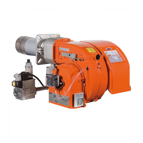
8) Motor 9) Air adjustment servomotor 9a) Manual air adjustment (TGB 45/60) 10) Air pressure switch MODEL Ø Ø TBG 45 TBG 45P TBG 60 TBG 60P ELECTRICAL BOX COMPONENTS 13) Equipment 14) Ignition transformer 15) Motor contactor (only for three-phase power supply) - Page 8 WORKING FIELD TBG 45 / 60 SINGLE STAGE WORKING FIELD TBG 45P / 60P TWO STAGE The working fields are obtained from test boilers corresponding to the standard EN267 and are indicatively for the combination burner-boiler. For correct working of the burner the size of the combustion chamber must correspond to current regulations;...
-
Page 9: Power Supply Line
1) To prevent severe drops in pres-sure on ignition it is advisble POWER SUPPLY LINE to have a length of piping of 1.5 to 2 metres between the point of application of the stabiliser or pressure reducer and the The gas supply scheme is shown in the diagram below. The gas burner. -
Page 10: Assembling The Gas Train
APPLICATION OF BURNER TO BOILER Position insulating seal 3 on the sleeve, placing cord 2 between the flange and the seal. slacken screws “6”, adjust the position of connection flange “5” so that the com- bustion head penetrates the furnace up to the length recom- mended by the generator manufacturer. -
Page 11: Wiring Diagram
WIRING DIAGRAM The three-phase power supply line must have a switch with fuses. The regulations further require a switch on the burner’s power sup- ply line, outside the boiler room and in an easily accessed position. For the electrical connections (line and thermostats), follow the wiring diagram enclosed. - Page 12 DESCRIPTION OF TBG 45 / 60 OPERATION DESCRIPTION OF TBG 45P - 60P OPERATION When the main switch and the I/O switch (22) on the electrical When the main switch and the I/O switch (22) on the electrical panel are closed, if the thermostats are closed, voltage will reach...
- Page 13 GAS BURNER CONTROL DEVICE GAS LME 22... Operational status During startup, status indication takes place according to the following table: indication Color code table for multicolor signal lamp (LED) Status Color code Color Waiting time «tw», other waiting states ........Ignition phase, ignition controlled Flashing yellow ............
-
Page 14: Methane Gas Ignition And Adjustment
0002934711; value of 10 % or O 2 = 3% for maximum supply. It is essential - for burner TBG 45 - 60 with manual adjustment, adjust the air to check, with a suitable instrument, that the percentage of for the second flame on the basis of the instructions given in... -
Page 15: Ionisation Current Measurement
tact when the air pressure in the burner reaches a sufficient IONISATION CURRENT MEASUREMENT value. The pressure switch connection circuit provides for auto control so it necessary for the contact to be actually closed To measure the ionisation current, remove the jumper when the fan is stopped (no air pressure in burner). - Page 16 ELECTRODES/IONISATION PROBE ADJUSTMENT DIAGRAM Legend: 1- Ionisation electrode Mod. 2- Ignition electrode TBG 45 - 45P 3- Deflector disk TBG 60P 4- Mixer TBG 60 5- Gas outlet pipe high air pressure behind the disk. It is advisable to adjust in such...
- Page 17 Value indicated by BURNER CAMS REGULATION SERVOMOTOR index 4 SQN72.XA4A20 FOR TBG ...P TBG 45 / 45P 3 ÷31 0 ÷ 3,2 TBG 60 / 60P 6÷ 34 0 ÷ 3,2 INSERTION AND DISINSERTION LEVER MOTOR CONNECTION ADJUSTABLE CAMS CAMSHAFT X= Distance between combustion head and disk;...
-
Page 18: Maintenance
MAINTENANCE Carry out periodic analysis of the exhaust combustion gas, checking the emissions. Periodically replace the gas filter when dirty. Check that all the components of the combustion head are in a good state, not deformed by the temperature and free from impurities or deposits from the installation environment or by poor combustion and check also the electrodes are working efficiently. - Page 19 figure 1. 3) Now remove the 4 nuts (5) in figure 2, dismantle the flame SINGLE STAGE AIR BURNER TBG 45 - 60 tube(6) and, after pulling off the lung (7) from its stud bolts, put ADJUSTMENT SCHEME it back in position with the threaded connection for anchoring the gas train turned upward.
- Page 20 TWO-STAGE GAS BURNERS: TROUBLE-SHOOTING GUIDE DETAILS OF PROBLEM POSSIBLE CAUSE SOLUTION 1) Disturbance to ionization current from igni- 1) Invert the ignition transformer power supply The apparatus goes into “lock- tion transformer.. (230V side) and check using an analog micro- out”...
- Page 21 SP - Antes de empezar a usar el quemador lea detenidamente el folleto “ADVERTENCIAS DIRIGIDAS AL USUARIO PARA USAR CON SEGURIDAD EL QUEMADOR” que va con el manual de instrucciones y que constituye una parte integrante y esencial del producto. - L e a a t e n t a m e n t e l a s i n s t r u c c i o n e s a n t e s d e p o n e r e n f u n c i o n a m e n t o l o s q u e m a d o r e s y efectuar las tareas de mantenimiento.
-
Page 22: Advertencias Generales
La eventual reparación de los aparatos tiene que hacerla solamente un centro de asistencia autorizado por BALTUR utilizando exclusivamente repuestos originales. Si no se respeta lo anteriormente se puede comprometer la seguridad del aparato. Para garantizar la eficacia del aparato y para que funcione correctamente es indispensable que el personal cualificado profesionalmente realice el mantenimiento periódicamente ateniéndose a... -
Page 23: Alimentación Eléctrica
ADVERTENCIAS DIRIGIDAS AL USUARIO PARA USAR EL QUEMADOR EN CONDICIONES DE SEGURIDAD PRELIMINARES ALIMENTACIÓN ELÉCTRICA • La seguridad eléctrica del aparato se consigue solo cuando el mismo está conectado correctamente a una buena instalación de puesta a tierra, realizado tal y como establecen las normas de seguridad vigentes. - Page 24 CARACTERISTICAS TECNICAS TBG 45 TBG 45P TBG 60 TBG 60P MAX kW POTENCIA TERMICA MIN kW FONCIONAMENTO Una etapa Dos etapas Una etapa Dos etapas ÉMISSION NOx mg/kWh < 80 (Classe III secondo EN 676) 0,50 0,75 MOTOR 2730 2800 r.p.m.
-
Page 25: Электрическая Схема
ЭЛЕКТРИЧЕСКАЯ СХЕМА МИНИМАЛЬНЫЙ ТОК ИОНИЗАЦИИ 3 µA ФАЗА ЗЕМЛЯ НЕЙТРАЛЬ ** ПО ЗАПРОСУ * ТОЛЬКО ДЛЯ LGB 21 а а... - Page 26 ЭЛЕКТРИЧЕСКАЯ СХЕМА МИНИМАЛЬНЫЙ ТОК ИОНИЗАЦИИ 3 µA ФАЗА ЗЕМЛЯ НЕЙТРАЛЬ ** ПО ЗАПРОСУ а а * ТОЛЬКО ДЛЯ LGB 21...
- Page 27 ЭЛЕКТРИЧЕСКАЯ СХЕМА МИНИМАЛЬНЫЙ ТОК ИОНИЗАЦИИ 3 µA ФАЗА ЗЕМЛЯ НЕЙТРАЛЬ ** ПО ЗАПРОСУ а а...
- Page 28 ЭЛЕКТРИЧЕСКАЯ СХЕМА МИНИМАЛЬНЫЙ ТОК ИОНИЗАЦИИ 3 µA ФАЗА SARI / YEŞİL ЗЕМЛЯ MAVİ НЕЙТРАЛЬ KAHV. RE.NGİ SİYAH ** ПО ЗАПРОСУ NOLU SİYAH а а KABL0...
- Page 29 SIGLA BURNER TERMINAL REGLETA DE BORNES DEL QUEMADOR BORNES DE RACCORD ÇÀÆÈÌÍÀß ÊÎÐÎÁÊÀ ÃÎÐÅËÊÈ BRÜLÖR TERMİNAL KLAMENSİ X1B/S POWER SUPPLY CONNECTOR CONECTOR DE ALIMENTACION CONNECTEUR ALIMENTATION РАЗЪЁМ ПИТАНИЯ BESLEME KONEKTÖRÜ X2B/S 2ND STAGE CONNECTOR 2DA ETAPA DEL CONECTADOR 2ME TAPE CONNECTEUR РАЗЪЁМ...
Need help?
Do you have a question about the TBG 45 and is the answer not in the manual?
Questions and answers