Table of Contents
Advertisement
Available languages
Available languages
Quick Links
Advertisement
Chapters
Table of Contents

Subscribe to Our Youtube Channel
Related Manuals for baltur TBG 35 PN


Summary of Contents for baltur TBG 35 PN
- Page 1 Manual instructions for use Manuale istruzioni per l’uso. TBG 35 PN - BRUCIATORI DI GAS A DUE STADI PROGRESSIVI / MODULANTE - TWO-STAGE PROGRESSIVE / MODULATING GAS BURNERS ISTRUZIONI ORIGINALI (IT) ORIGINAL INSTRUCTIONS ARE (IT) 0006081436_201611...
-
Page 3: Table Of Contents
DISPOSITIVO DI REGOLAZIONE MANUALE PRESSIONE GAS IN TESTA ......................... 18 ISTRUZIONI MONTAGGIO RIDUZIONI PER GPL ................................18 ISTRUZIONI PER L’ACCERTAMENTO DELLE CAUSE DI IRREGOLARITÀ NEL FUNZIONAMENTO E LORO ELIMINAZIONE ........ 19 SCHEMA ELETTRICO TBG 35 PN ....................................20 1 / 22 0006081436_201611... - Page 4 L’eventuale riparazione dei prodotti dovrà essere effettuata solamente incombusti nocivi o inquinanti oltre i limiti consentiti dalle norme vigenti. da un centro di assistenza autorizzato dalla BALTUR utilizzando d) Verifi care la funzionalità dei dispositivi di regolazione e di sicurezza.
- Page 5 ALIMENTAZIONE ELETTRICA - b) la regolazione della portata del combustibile secondo la potenza • La sicurezza elettrica dell’apparecchio è raggiunta soltanto quando lo richiesta al bruciatore; stesso è corretamente collegato a un’efficace impianto di messa a terra, - c) che il bruciatore sia alimentato dal tipo di combustibile per il quale eseguito come previsto dalle vigenti norme di sicurezza.
-
Page 6: Caratteristiche Tecniche
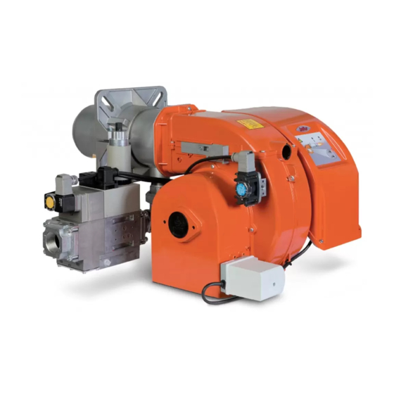
CARATTERISTICHE TECNICHE TBG 35 PN POTENZA TERMICA FUNZIONAMENTO Bistadio progressivo / Modulante EMISSIONI NOx mg/kWh < 80 (Classe III secondo EN 676) 0,37 MOTORE VENTOLA r.p.m. 2760 POTENZA ELETTRICA ASSORBITA* 0,56 TRASFORMATORE D’ACCENSIONE 26 kV - 40 mA - 230/240 V - 50/60 Hz TENSIONE ALIMENTAZIONE 1N ~ 230 V ±... - Page 7 DIMENSIONI DI INGOMBRO 1) Testa di combustione 2) Guarnizione 3) Flangia attacco bruciatore 4) Dispositivo regolazione testata 5) Coperchio chiocciola 6) Flangia attacco rampa gas 7) Quadro elettrico 8) Motore 9) Servomotore regolazione aria (TBG 35P) 9a) Regolazione aria manuale (TGB 35) 9b) Servomotore regolazione aria (TBG 35PN) 10) Pressostato aria MOD.
- Page 8 CAMPO DI LAVORO TBG 35P / PN TBG 35 mbar Nm /h(Metano) Nm /h(G.P.L.) I campi di lavoro sono ottenuti su caldaie di prova rispondenti alla norma EN676 e sono orientativi per gli accoppiamenti bruciatore-caldaia. Per il corretto funzionamento del bruciatore le dimensioni della camera di combustione devono essere rispondenti alla normativa vigente;...
-
Page 9: Linea Di Alimentazione
LINEA DI ALIMENTAZIONE Lo schema di principio della linea di alimentazione gas è riportato nella figura sotto. La rampa gas è omologata secondo normativa EN 676 e viene fornita separatamente dal bruciatore. Occorre installare, a monte della valvola gas, una valvola di intercettazione manuale e un giunto antivibrante, disposti secondo quanto indicato nello schema. -
Page 10: Montaggio Rampa Gas
Vite fissaggio tubo rigido Tubo rigido rilevamento pressione in camera di combustione Presa di pressione in camera di combustione Tagliare a filo diffusore Tubo trasmissione pressione in camera di combustione MONTAGGIO RAMPA GAS Sono possibili diverse configurazioni di montaggio della rampa gas in base alle diverse esigenze di installazione, come evidenziato nel disegno a fianco (8, 8a, 9). -
Page 11: Collegamenti Elettrici
COLLEGAMENTI ELETTRICI La linea di alimentazione monofase deve essere provvista di interruttore con fusibili. Per i collegamenti elettrici (linea e termostati) attenersi allo schema elettrico allegato. Per eseguire il collegamento del bruciatore alla linea di alimentazione procedere come segue: 1) Inserire la spina a 7 poli e 4 poli per la versione “P”, nelle apposite prese situate al di sotto della basetta di supporto quadro elettrico come illustrato nella figura 1. -
Page 12: Descrizione Del Funzionamento
Nel caso di assenza fiamma, l’apparecchiatura si arresta in “bloc- DESCRIZIONE DEL FUNZIONAMENTO co di sicurezza” (accensione led 20) entro 3 secondi dall’apertu- ra della valvola principale. In caso di blocco di sicurezza le valvole Alla chiusura dell’interruttore generale, se i termostati sono chiu- vengono immediatamente richiuse. - Page 13 avverte l’odore caratteristico del gas e quindi chiudere il rubinetto. è da considerarsi normale perché nella tubazione della rampa Attendere il tempo che si presume sufficiente, in funzione delle valvole esiste ancora aria che deve essere evacuata prima di condizioni specifiche, affinché il gas presente nel locale si sia poter avere la fiamma stabile.
- Page 14 della pressione che si riscontra di volta in volta. I pressostati 0002933651) Bisogna ridurre l’angolo di apertura della serran- risultano collegati elettricamente in serie, quindi l’intervento (in- da dell’aria per ridurre la portata di gas e viceversa. Per varia- teso come apertura di circuito) di uno qualsiasi dei pressostati re il rapporto gas/aria vedi istruzioni valvole gas pneumatiche gas, non consente l’inserzione dell’apparecchiatura e quindi del installate.
-
Page 15: Istruzioni Per Il Funzionamento In Modalita' Manuale Del Bruciatore
- per diminuirla. Terminato il controllo, reinserire la spina a 4 poli (A) in modo da ripristinare il funzionamento automatico della modulazione. SCHEMA REGOLAZIONE ELETTRODI / SONDA IONIZZAZIONE 0002935683_01 TBG 35 PN 1- Elettrodo ionizzazione Mod. 2- Elettrodo accensione TBG 35 PN... -
Page 16: Apparecchiatura Di Comando E Controllo Lme 22
APPARECCHIATURA DI COMANDO E CONTROLLO LME 22... Indicazione stato operativo Durante l’avviamento, l’indicazione dello stato avviene secondo la seguente tabella: Tabella codici colore per indicatore luminoso multicolore (LED) Legenda Stato Codice colore Colore ..Acceso fisso Tempo di attesa “tw”, altri stati di attesa Spento ¡... -
Page 17: Regolazione Dell' Aria Sulla Testa Di Combustione
REGOLAZIONE DELL’ ARIA SULLA TESTA Valore indicato BRUCIATORE DI COMBUSTIONE dall’indice 4 TBG 35 PN 3 ÷31 0 ÷ 6 La testa di combustione è dotata di un dispositivo di regolazione che permette di aprire o chiudere il passaggio dell’aria tra il disco X= Distanza testa-disco;... -
Page 18: Regolazione Camme Servomotore Sqn 72.6A4A20
REGOLAZIONE CAMME SERVOMOTORE SQN 72.6A4A20 P E R N O I N S E R Z I O N E E D ESCLUSIONE ACCOPPIAMENTO CAMME REGOLABILI MOTORE - ALBERO CAMME SCALA DI RIFERIMENTO INDICATORE DI POSIZIONE APERTURA MASSIMA ARIA (90°) CHIUSURA TOTALE ARIA (BRUCIATORE FERMO) (0°) APERTURA MINIMA ARIA (MINORE DI CAMMA IV) (10°) APERTURA ARIA D’ACCENSIONE... -
Page 19: Manutenzione
MANUTENZIONE Effettuare periodicamente l’analisi dei gas di scarico della combustione verificando la correttezza dei valori di emissioni. Sostituire periodicamente il filtro del gas quando è sporco. Verificare che tutti i componenti della testa di combustione siano in buono stato, non deformati dalla temperatura e privi di impurità o depositi derivanti dall’ambiente di installazione o da una cattiva combustione, controllare l’efficienza degli elettrodi. -
Page 20: Dispositivo Di Regolazione Manuale Pressione Gas In Testa
DISPOSITIVO DI REGOLAZIONE MANUALE ISTRUZIONI MONTAGGIO RIDUZIONI PER PRESSIONE GAS IN TESTA Per un corretto funzionamento delle valvole proporzionali in tutto Nel caso di funzionamento con combustibile GPL inserire le apposite il range di modulazione è necessario, durante la fase di prima riduzioni fornite a corredo del bruciatore. -
Page 21: Istruzioni Per L'accertamento Delle Cause Di Irregolarità Nel Funzionamento E Loro Eliminazione
ISTRUZIONI PER L’ACCERTAMENTO DELLE CAUSE DI IRREGOLARITÀ NEL FUNZIONAMENTO E LORO ELIMINAZIONE IRREGOLARITÀ CAUSA POSSIBILE RIMEDIO L’apparecchio va in “blocco” con ) Disturbo della corrente di Ionizzazione da 1) Invertire l’alimentazione (lato 230V) del fiamma (lampada rossa accesa). parte del trasformatore di accensione. trasformatore di accensione e verificare con Guasto circoscritto al dispositivo micro-amperometro analogico... - Page 22 20 / 22 0006081436_201611...
- Page 23 SIGLA APPARECCHIATURA CONTROLLO TENUTA VALVOLE ELETTRODO DI IONIZZAZIONE SPIA BLOCCO ESTERNA SPIA DI FUNZIONAMENTO RELE’ AUSILIARIO MOTORE VENTOLA REGOLATORE ELETTRONICO CONTAORE PRESSOSTATO ARIA PRESSOSTATO DI MINIMA POTENZIOMETRO PULSANTE SBLOCCO TRASFORMATORE D'ACCENSIONE TERMOSTATO CALDAIA TERMOSTATO DI SICUREZZA CONNETTORE Pm CONNETTORE YP CONNETTORE TRASFORMATORE CONNETTORE MOTORE CONNETTORE PA...
- Page 24 22 / 22 0006081436_201611...
- Page 25 Before using the burner for the first time please carefully read the chapter “WARNINGS NOTES FOR THE USER : HOW TO USE THE BURNER SAFELY” in this instruction manual, which is an integral and essential part of the product. The works on the burner and on the esystem have to be carried out only by competent people.
-
Page 26: Warnings For Use In Safety Conditions
In such case get in touch with only qualifi ed technicians. Any c) Carry out a check on combustion to ensure the production of no- product repairs must only be carried out by BALTUR authorised assi- xious or polluting unburnt gases does not exceed limits permitted stance centres using only original spare parts. - Page 27 ELECTRICAL SUPPLY • Have qualifi ed technicians check the following: • The equipment is electrically safe only when it is correctly connected to an a) that the feed line and the train comply with current law and regulations. effi cient ground connection carried out in accordance with current safety b) that all the gas connections are properly sealed.
-
Page 28: Technical Specifications
TECHNICAL SPECIFICATIONS TBG 35 PN THERMAL CAPACITY Modulating / Progressive two OPERATION stage burner < 80 (Class III according to EN NOx EMISSIONS mg/kWh 676) 0,37 FAN MOTOR 2760 r.p.m. 0,56 ABSORBED ELECTRICAL POWER* 26 kV - 40 mA - 230/240 V - 50/60 IGNITION TRANSFORMER 1N ~ 230 V ±10%- 50 Hz... - Page 29 OVERALL DIMENSIONS Combustion head Seal Burner connection flange Combustion head adjustment device Cover Gas train connector flange Electrical panel Motor Air adjustment servomotor (TBG 35P) Manual air adjustment (TGB 35) Air adjustment servomotor (TBG 35PN) Air pressure switch MODEL min max Ø Ø...
- Page 30 OPERATING RANGE TBG 35P / PN TBG 35 mbar Nm /h(Metano) Nm /h(G.P.L.) The working ranges are obtained from test boilers corresponding to the standard EN676 and are indicative of the combination burner-boiler. For correct working of the burner the size of the combustion chamber must correspond to current regulations;...
-
Page 31: Gas Supply Line
GAS SUPPLY LINE The gas supply scheme is shown in the diagram below. The gas train is certified in accordance with regulation EN 676 and is supplied separately to the burner. A manual shut off valve and an anti-vibration joint must be installed upstream of the gas valve, as shown in the diagram. GENERAL GAS BURNER SYSTEM GAS TRAIN SUPPLIED BY THE CONSTRUCTOR RESPONSIBILITY OF THE INSTALLER... -
Page 32: Assembling The Gas Train
Rigid pipe fixing screw Rigid pipe detecting pressure in the combustion chamber Pressure tap in the combustion chamber Cut in line with diffuser Pressure transmission pipe in the combustion chamber ASSEMBLING THE GAS TRAIN There are different possible assembly configurations for the gas train according to the different installation requirements, as shown in the diagram (8, 8a, 9). -
Page 33: Electrical Connections
ELECTRICAL CONNECTIONS The monophase power supply line must have a switch with fuses. For the electrical connections (line and thermostats), follow the attached wiring diagram. To carry out the connection of the burner to the power supply line proceed as follows: 1) Insert the 7 and 4 pole plugs for version "P", in the appropriate sockets located below the electrical panel base as shown in figure 1. -
Page 34: Description Of Working
DESCRIPTION OF WORKING increase in the gas flow up to the maximum set value. If there is no flame, the appliance shuts down in “safety lock-out” If when the main switch is closed, the thermostats are closed, the mode (led 20 comes on) within 3 seconds of the opening of the voltage reaches the command and control equipment which starts main valve. -
Page 35: Starting Up And Regulation With Methane Gas
STARTING UP AND REGULATION valve in the attached manual for the gas train installed WITH METHANE GAS 9) For initial adjustment operate the burner manually using the appropriate modulation connector supplied as standard (see section "instructions for manual 1) Check that combustion head penetrates the operation of burner"). - Page 36 ment into the safety (lock-out) state if the air pressure is not optimal value of 10 % or 0 = 3% for maximum supply. what it should be. The pressure switch must therefore be set to It is essential to check, with a suitable instrument, that close the contact (closed during operation) when air pressure the percentage of carbon monoxide (CO) present in in the burner is sufficient.
- Page 37 MANUAL BURNER OPERATION IONIZATION CURRENT INSTRUCTIONS Minimum current required to enable the unit to work is 3 µA for LME 2. Combustion may be checked throughout the entire modulation The burner provides a significantly higher current and therefore range by means of manual adjustments to operation. Use the does not normally require any checks at all.
-
Page 38: Control Equipment And Commands For Gas Burners Lme 22
CONTROL EQUIPMENT AND COMMANDS FOR GAS BURNERS LME 22... Status indication During startup, status indication takes place according to the following table: Colour code table for multicolour signal lamp (LED) Legend Colour Status Colour code ..Fixed activa- tion Waiting time "tw", other waiting states ¡.......... - Page 39 ELECTRODES/IONISATION PROBE ADJUSTMENT DIAGRAM 0002935683_01 Legend: 1- Ionisation electrode Mod. 2- Ignition electrode TBG 35 PN 3- Deflector disk 4- Mixer 5- Gas outlet pipe E- ATTENTION: Central nozzle hole outlet near the electrode end. ADJUSTING AIR ON THE Value indicated by...
-
Page 40: Servomotor Cams Adjustment Sqn 72.6A4A20
SERVOMOTOR CAMS ADJUSTMENT SQN 72.6A4A20 INSERTION AND DISINSERTION LEVER MOTOR CONNECTION - ADJUSTABLE CAMS CAMSHAFT REFERENCE SCALE POSITION INDICATOR MAXIMUM AIR OPENING (90°) TOTAL AIR CLOSURE (BURNER AT STANDSTILL (0°) MINIMUM AIR OPENING (LOWER THAN CAM IV) (10°) AIR IGNITION OPENING (HIGHER THAN CAM III) (20°) TO ADJUST THE SETTING OF THE CAM USED, USE THE RESPECTIVE RINGS (I -II - III - IV) THE SCALE ON THE RING... -
Page 41: Maintenance
MAINTENANCE Periodically analyse combustion gases and check emissions val- ues. Periodically replace the gas filter, whenever it is dirty. Check that all components of the combustion head are in good condition, have not been deformed by high temperatures and con- tain no impurities or deposits from the installation environment or from poor combustion;... -
Page 42: Manual Head Gas Pressure Adjustment Device
MANUAL HEAD GAS PRESSURE REDUCERS ASSEMBLY INSTRUCTIONS FOR LPG ADJUSTMENT DEVICE In the event of functioning with LPG fuel connect the appropriate For the correct operation of the proportional valves throughout the reducers supplied with the burner. For the assembly of the reducers entire modulation range, during the initial phase of adjusting the follow the instructions below. -
Page 43: How To Find The Causes Of Improper Working Of Burners Using Two-Stage Light Oil And How To Rectify Them
HOW TO FIND THE CAUSES OF IMPROPER WORKING OF BURNERS USING TWO-STAGE LIGHT OIL AND HOW TO RECTIFY THEM IRREGULARITIES POSSIBLE CAUSE SOLUTION The apparatus goes into “lock- 1) Disturbance to ionization current from the 1) Invert the ignition transformer power supply out”... - Page 44 20 / 22 0006081436_201611...
- Page 45 CONTROL BOX VALVES TIGHTNESS CONTROL PHOTORESISTANCE / IONISATION ELECTRODE / UV PHOTOCELL EXTERNAL BLOCK LAMP / AUXILIARY RESISTANCES LAMP OPERATION LIGHT AUXILIARY RELE’ MOTOR REGULATEUR ELECTRONIQUE HOUR METER AIR PRESSURE SWITCH GAS MIN. PRESSURE SWITCH POTENTIOMETER RE-SET PUSH BUTTON IGNITION TRANSFORMER BOILER THERMOSTAT SAFETY THERMOSTAT POWER SUPPLY CONNECTOR...
- Page 46 22 / 22 0006081436_201611...
- Page 48 - Il presente catalogo riveste carattere puramente indicativo. La casa, pertanto, si riserva ogni possibilità di modifica dei dati tecnici e quant’altro in esso riportato. - Technical data in this brochure are given as information only. Baltur reserves the right to change specification, without notice.
Need help?
Do you have a question about the TBG 35 PN and is the answer not in the manual?
Questions and answers