
Subscribe to Our Youtube Channel
Related Manuals for Fimap MAGNA


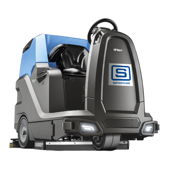
Summary of Contents for Fimap MAGNA
- Page 1 MAGNA PROFESSIONAL SCRUBBING MACHINES USE AND MAINTENANCE MANUAL ORIGINAL INSTRUCTIONS DOC. 10080263 - Ver. AC - 11-2019...
-
Page 3: Table Of Contents
CONTENTS CONTENTS ..........................3 GENERAL DESCRIPTION ......................5 GENERAL SAFETY REGULATIONS ........................5 SYMBOLS USED IN THE MANUAL ........................5 PURPOSE AND CONTENT OF THE MANUAL ..................... 6 STORING THE USE AND MAINTENANCE MANUAL ................... 6 ON CONSIGNMENT OF THE MACHINE ......................6 INTRODUCTORY COMMENT .......................... - Page 4 EXTRA BRUSH HEAD PRESSURE ........................23 ACOUSTIC SIGNALLING DEVICE ........................23 WORKING HEADLIGHTS (OPTIONAL) ......................23 EMERGENCY BUTTON ............................23 HOUR METER ..............................23 BATTERY CHARGE LEVEL INDICATOR ......................23 BRAKING CONTROL ............................24 ALARM SCREEN ..............................24 ACTIVATING THE SIDE BRUSH (OPTIONAL) ....................25 ACTIVATING DETERGENT SOLUTION RECYCLING (FLR VERSION) ............
-
Page 5: General Description
GENERAL DESCRIPTION The descriptions contained in this document are not binding. The company therefore reserves the right to make any modifications at any time to elements, details, or accessory supply, as considered necessary for reasons of improvement or manufacturing/commercial requirements. The reproduction, even partial, of the text and drawings contained in this document is prohibited by law. -
Page 6: Purpose And Content Of The Manual
TECHNICAL DESCRIPTION The Magna is a floor scrubbing machine that can work on various types of floor and dirt thanks to the mechanical action of a brush and the chemical action of a water-detergent solution. As it advances, it collects the dirt removed, along with the detergent solution not absorbed by the flooring itself. -
Page 7: Technical Data
TECHNICAL DATA Magna TECHNICAL DATA Magna [KMS] Cylindrical Nominal input power [IEC 60335-2-72; IEC 62885-9] 3,05 3,05 Working capacity up to 3150 2888 Working width [IEC 62885-9] Working width with the lateral brush 1050 1220 Squeegee width 1045 1045 Nominal power of brush motor/s [IEC 62885-9] Total width of brushes [IEC 62885-9] No. -
Page 8: Main Machine Components
MAIN MACHINE COMPONENTS The machine's main components are the following: 22. Horn button. 23. Button for activating the automatic dosing system or the automatic 1. Lateral scrubbing brush head (optional). recycle system (optional). 2. Scrubbing brush head. 24. Side brush control button (optional). 3. -
Page 9: Choosing And Using Brushes
CHOOSING AND USING BRUSHES POLYPROPYLENE BRUSH (PPL) Used on all types of floors. Good resistance to wear and tear, and hot water (no greater than 50°C.). PPL is non-hygroscopic and therefore retains its characteristics even when working in wet conditions. ABRASIVE BRUSH The bristles of this type of brush are charged with highly aggressive abrasives. -
Page 10: Labels Used On The Machine
Brush head body standby position symbol: Applied to the steering column to indicate the brush head control lever direction of rotation for bringing the brushes to their standby position. Squeegee body working position symbol: Applied to the steering column to indicate the squeegee control lever direction of rotation for bringing the squeegee to its working position. -
Page 11: Handling The Packed Machine
Label for the detergent solution automatic recycling system control (optional): Applied near the steering column to indicate the button for activating or switching off the optional detergent solution automatic recycling system kit. Label for the side brush control (optional): Applied near the steering column to indicate the button for activating or switching off the side brush control system. Label for detergent solution tap command: Applied in the vicinity of the control column to identify the detergent solution tap's control lever. -
Page 12: Unpacking The Machine
HOW TO UNPACK THE MACHINE The machine is shipped in specific packaging. To remove it, proceed as follows: 1. Place the lower part of the outer packaging in contact with the floor. N.B.: use the pictograms printed on the box as a reference. 2. -
Page 13: How To Move The Machine
HOW TO MOVE THE MACHINE To transport the machine safely, proceed as follows: DANGER: before starting any task, make sure the current regulations concerning the safe transport of dangerous substances are scrupulously observed. 1. Check to make sure that the solution tank and the recovery tank are empty. If this is not the case, empty them (see the sections titled “EMPTYING THE SOLUTION TANK”... -
Page 14: Machine Preparation
PREPARATION OF MACHINE MACHINE SAFETY To ensure that work is carried out in the best safety conditions, proceed as follows: 1. Make sure the solution tank is empty. If this is not the case, empty it (read "EMPTYING THE SOLUTION TANK"). -
Page 15: Type Of Battery To Be Used
For battery maintenance and recharging, respect the instructions provided by the battery manufacturer. When the batteries reach the end of their service life, they must be disconnected by a FIMAP assistance centre technician or by a specialised and properly trained worker, and must be subsequently removed from the battery compartment using suitable lifting devices. -
Page 16: Inserting Water System Filter
INSERTING WATER SYSTEM FILTER Before using the machine for the first time the water system filter needs to be reset, for shipping reasons the filter cartridge and the cap have been removed. To insert the filter cartridge in the water system filter body proceed as follows: 1. -
Page 17: Fitting The Brush Head Brushes (Scrubbing Version)
ATTENTION: always use detergents whose manufacturer's label indicates their suitability for scrubbing machines. Do not use acid or alkaline products or solvents without this indication. ATTENTION: the dosing system is suitable for frequent maintenance cleaning. Acid or alkaline maintenance detergent can be used with pH values between 4 and 10 and that do not contain: oxidising agents, chlorine or bromine, formaldehyde, mineral solvents. -
Page 18: Fitting The Brush Head Brushes (Sweeping Version)
ASSEMBLING THE BRUSH HEAD BRUSHES (SWEEPING VERSION) To fit the brush on the brush head body, proceed as follows: 1. Make sure the machine has been secured (see the section titled “SECURING THE MACHINE”). CAUTION: these operations must be carried out using protective gloves to avoid any possible contact with the edges or tips of metal objects. -
Page 19: Preparing To Work
N.B.: the feet should be positioned keeping the heels on the footrest, the sole of the foot directly below the fingers should push the pedals. N.B.: the ideal position is that which allows you to grip the steering wheel correctly with the palms slightly lower than the shoulders. With a good grip on the steering wheel, the elbows should be bent by about 120°. -
Page 20: Work
11. Move to the left side of the machine and open the left side casing (5) (Fig. 5). 12. Make sure the electronic brake is engaged. If it isn't, turn the lever (6) in the direction of the arrow (Fig. 6). The traction gear motor is located on the rear right-hand side of the machine. -
Page 21: Scrubbing Without Drying
The machine can be used for the following types of work: • SCRUBBING WITHOUT DRYING; • SCRUBBING WITH DRYING; • DRYING; As an example, we will look at the SCRUBBING WITH DRYING work type. To begin working in this mode, proceed as follows: 1. -
Page 22: Scrubbing With Drying
SCRUBBING WITH DRYING To carry out “SCRUBBING AND DRYING” tasks, proceed as follows: 1. Sit on the driver’s seat and turn on the machine. 2. Lower the brush head body by turning the brush head control lever (3) on the rear part of the steering column (Fig. 3). 3. -
Page 23: Extra Brush Head Pressure
N.B.: in order to disengage the reverse gear, disengage the lever (7) underneath the steering wheel (Fig. 7). N.B.: once the lever has been engaged (7), the acoustic signalling device will be activated in order to signal that the machine's reverse gear has been engaged. -
Page 24: Braking Control
BRAKING CONTROL The machine has an encoder to help braking and also a mechanical brake. If the machine is moving and the accelerator pedal (6) is released, the machine brakes, decelerating gently, until it stops the encoder. Only when the encoder has stopped is the electric brake engaged. If the machine is moving and the brake pedal (19) (Fig. -
Page 25: Activating The Side Brush (Optional)
ACTIVATING THE SIDE BRUSH (OPTIONAL) If the side brush needs to be used during the floor scrubbing operations, and therefore with the brush head in its working position, press the side brush head activation/deactivation button (15) on the left-hand side of the steering column (Fig. 14). N.B.: when the side brush is in function, the LED indicator light inside the button (15) will be on. -
Page 26: Automatic Request For Technical Assistance (Ffm Version)
The machine has an automatic service for activating an urgent technical assistance request. To activate this function, the operator simply needs to press the button under the hatch bearing the symbol “SOS”. N.B.: in order to activate this urgent technical assistance request the machine needs to be equipped with the FIMAP FLEET MANAGEMENT kit. -
Page 27: Overflow Device
OVERFLOW DEVICE The machine is not equipped with an overflow device, because the volume of the recovery tank is greater than the capacity of the solution tank. In extraordinary cases, there is a mechanical device (float) under the recovery tank lid that, when the recovery tank is full, shuts off the air to the vacuum motor intake to protect it;... - Page 28 INTERVAL MACHINE COMPONENTS PROCEDURE Clean the filter in the machine's water system (see “CLEANING THE WATER Machine water system SYSTEM FILTER”). Check that the rubber blades on the squeegee body are intact and inspect for Squeegee rubber blades wear; if necessary, replace these (see “REPLACING THE SQUEEGEE BODY RUBBER BLADES”).
-
Page 29: Emptying The Recovery Tank
DRAINING THE RECOVERY TANK Proceed as follows to empty the recovery tank: 1. Remove the drainage hose of the recovery tank from the clamps; it is located at the rear of the machine (Fig. 1). 2. Bend the end of the drainage tube in order to create a choke and prevent the content from coming out (Fig. 2), then position the tube on the discharge surface, unscrew the cap, and gradually release the tube. -
Page 30: Cleaning The Side Brush (Scrubbing Version)
N.B.: you are advised to invert the right and left-hand brushes every day. ATTENTION: if the brushes are not new, and have deformed bristles, it is better to reassemble them in the same position in order to prevent the different inclination of the bristles from overloading the brush motor, as well as to prevent excessive vibrations. CLEANING THE LATERAL BRUSH (SCRUBBING VERSION) Careful cleaning of the brush guarantees better cleaning of the floor as well as a longer brush head gearmotor lifespan. -
Page 31: Draining The Solution Tank
3. Remove the recycle filter (25), only valid for FLR versions (Fig. 30). 4. Rinse the recycle filter thoroughly under the jet of the tank cleaning accessory. N.B.: use a spatula to eliminate any dirt that is particularly difficult to remove. 5. -
Page 32: Emergency Maintenance
EXTRAORDINARY MAINTENANCE Before carrying out any extraordinary maintenance operations, proceed as follows: 1. Take the machine to the maintenance area. N.B.: the place given over to this operation must comply with current environmental protection regulations. 2. Make sure the machine is in a safe condition (see chapter “MACHINE SAFETY MEASURES”). -
Page 33: Replacing The Side Squeegee Splashguard Rubber Blades
4. Remove the splash guards (12) from the left splash guard body and replace it with a new one or else turn it around (Fig. 11). 5. Repeat the operations in reverse order to reassemble all the parts. 6. Repeat the operations just carried out also for the right side casing as well. REPLACING THE SIDE SQUEEGEE SPLASHGUARD RUBBER BLADES If the splashguard rubber blades of the side squeegee are damaged they cannot work properly, namely they cannot convey the dirty detergent solution towards the squeegee, therefore the rubber blades need to be checked. -
Page 34: Adjustment Interventions
ADJUSTMENT INTERVENTIONS ADJUSTING THE SQUEEGEE BODY'S RUBBER BLADES The careful adjustment of the squeegee body rubber blades guarantees better cleaning of the floor. To adjust the squeegee body blades, proceed as follows: 1. Sit on the driver’s seat. 2. Insert the key (1) into the main switch on the control panel. Bring the main switch to its "I" position by turning the key (1) a quarter turn clockwise (Fig. -
Page 35: Adjusting The Brush Head Body Side Splash Guards (Scrubbing Version)
N.B.: by decreasing the distance between the squeegee support and the floor, the rubber blades present in the squeegee's body move closer to the floor. N.B.: the right-hand and left-hand knobs must be rotated the same number of times, so that the squeegee is parallel to the floor when it is working. -
Page 36: Adjusting The Side Brush (Sweeping Version)
ADJUSTING THE SIDE BRUSH (SWEEPING VERSION) If the side brush does not channel the dirt efficiently towards the centre of the machine, you must adjust its height in relation to the ground, as follows: 1. Sit on the driver’s seat. 2. -
Page 37: Troubleshooting
TROUBLESHOOTING This chapter lists the most common problems linked with the use of the machine. If you are unable to resolve the problems with the information given here, please contact your nearest assistance centre. PROBLEM POSSIBLE CAUSE SOLUTION Make sure that the main switch is in its "I" position, otherwise turn the key The main switch is set to “0”. -
Page 38: Ec Declaration Of Conformity
Via Invalidi del Lavoro, 1 37059 Santa Maria di Zevio (VR) declares under its sole responsibility that the products FLOOR SCRUBBING MACHINES mod. Magna - Magna Cylindrical comply with the provisions of Directives: • 2006/42/EC: Machinery Directive. • 2014/30/EU: Electromagnetic compatibility directive. - Page 40 FIMAP - Via Invalidi del Lavoro, 1 - 37059 S. Maria di Zevio - Verona - Italy Tel. +39 045 6060411 – Fax +39 045 6060417 – E-mail: fimap@fimap.com www.fimap.com...
Need help?
Do you have a question about the MAGNA and is the answer not in the manual?
Questions and answers