
Subscribe to Our Youtube Channel
Related Manuals for Fimap MMX 43B


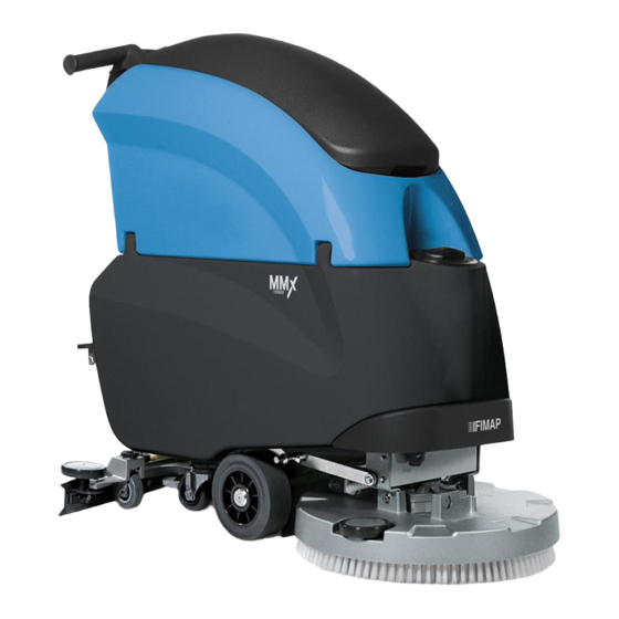
Summary of Contents for Fimap MMX 43B
- Page 1 USE AND MAINTENANCE MANUAL MMX B-BT 2014 ED. 08-2014 TRANSLATION OF THE ORIGINAL INSTRUCTIONS Doc. 10016247 Ver.
-
Page 2: Table Of Contents
CONTENTS CONTENTS ..............................................1 SYMBOLS USED IN THE MANUAL ......................................3 QUICK REFERENCE (ELECTRONIC DOCUMENT): .................................. 3 BOOKMARKS: ............................................ 3 LINK PAGE: ............................................3 PURPOSE AND CONTENT OF THE MANUAL ................................... 4 TARGET GROUP............................................4 STORAGE OF USE AND MAINTENANCE MANUAL ................................. 4 ON CONSIGNMENT OF THE APPLIANCE .................................... - Page 3 THE APPLIANCE DOES NOT SWITCH ON ..................................33 THE BATTERIES ARE NOT CHARGED CORRECTLY ..............................33 THE DEVICE HAS A VERY LOW OPERATING AUTONOMY ............................33 THE APPLIANCE DOES NOT MOVE ....................................34 INSUFFICIENT WATER ON THE BRUSHES .................................. 34 THE DEVICE DOES NOT CLEAN CORRECTLY ................................
-
Page 4: Symbols Used In The Manual
The descriptions contained in this document are not binding. The company therefore reserves the right to make any modifications at any time to elements, details, or accessory supply, as considered necessary for reasons of improvement or manufacturing/commercial requirements. The reproduction, even partial, of the text and drawings contained in this document is prohibited by law. -
Page 5: Purpose And Content Of The Manual
This manual is aimed at operators and qualified technicians responsible for equipment maintenance. Operators must not perform operations that should be carried out by qualified technicians. FIMAP SpA cannot be held liable for damages resulting from failure to comply with this prohibition. -
Page 6: General Safety Regulations
GENERAL SAFETY REGULATIONS The regulations below must be carefully followed in order to avoid harm to the operator and damage to the appliance. WARNING: Carefully read the labels on the appliance. Do not cover them for any reason and replace them immediately if they become damaged. •... -
Page 7: Technical Data
TECHNICAL DATA MMx 43 B MMx 43 BT MMx 50 B MMx 50 BT MMx 52 B MMx 52 BT Rated power Working width Width of rear squeegee Work capacity 1250 1750 1500 2000 1450 1960 Brush diameter No. / ∅Ø mm 1 / 420 1 / 420 1 / 510... -
Page 8: Symbols Used On The Appliance
SYMBOLS USED ON THE APPLIANCE Main switch or key switch symbol It is used on the instrument panel to indicate the green or red warning light showing that the main key switch is either on (I) or off (0). Symbol used in the solution tank to indicate the maximum temperature of the water used to fill the solution tank. Tap position symbol. - Page 9 SYMBOLS USED ON THE APPLIANCE Symbol for water amount adjustment (FSS system only). Used on the control panel to indicate the knob for adjusting the water level in the machine's water circuit. Brush uncoupling symbol (only for single-disc versions). Used on the control panel to indicate the button for uncoupling the brush. Symbol for active brush uncoupling system (only for single-disc versions).
-
Page 10: Preparation Of The Appliance
PREPARATION OF THE APPLIANCE HANDLING THE PACKED APPLIANCE The device is delivered in dedicated packaging. The packaging elements (plastic bags, clips, etc.) are potentially hazardous, and, therefore, must not be left within the reach of children, incapacitated persons, etc. The device is housed in dedicated packaging fitted with a pallet to facilitate fork-lift handling. -
Page 11: Component Positioning
PREPARATION OF THE APPLIANCE COMPONENT POSITIONING 11. Hinge to close the tanks The control panel components are identified as follows: 12. Compartment for battery charger / storage (depending on the Levers to activate brushes/traction (located beneath the grip) model) Water outlet adjustment switch (Versions with FSS) 13. -
Page 12: Type Of Battery
PREPARATION OF THE APPLIANCE TYPE OF BATTERY To power the device you can use: lead tubular plate traction batteries with liquid electrolyte. • airtight traction batteries with gasrecombination gel technology or AGM. • OTHER TYPES CANNOT NOT BE USED. Every battery consists of DIN-type elements connected in series and supplying 12V power to the clamps. The battery compartment can house two 12V batteries. -
Page 13: Battery Charger Connection (Only For Systems Without Cb)
PREPARATION OF THE APPLIANCE House the batteries in the compartment, positioning the poles “+” and “-“ opposite each other Connect to the battery drop cable (1) to the "+" and "-" terminals, so as to create a 24V voltage at the terminals. Connect the battery connector (2) to the general system connector (3). -
Page 14: Battery Charger Connection (Only For Systems With Cb)
PREPARATION OF THE APPLIANCE 10. BATTERY CHARGER CONNECTION (only for systems with CB) In order not to cause permanent damage to individual battery elements, it is essential to avoid their complete discharge by recharging them within a few minutes from the "discharged battery" warning light being switched on. ATTENTION: Never leave individual battery elements completely discharged, even if the appliance is not in operation. -
Page 15: 11. Hour Meter
PREPARATION OF THE APPLIANCE 12. When the recharge cycle is complete, disconnect the battery charger power supply cable from wall plug. 13. Disconnect the battery charger cable from the charger socket. 14. Close the drawer. 11. HOUR METER The control display is on the rear of the appliance. The second screen that appears after it is switched on shows the appliance's total usage time. -
Page 16: 14. Filling The Solution Tank
PREPARATION OF THE APPLIANCE 14. FILLING THE SOLUTION TANK Before filling the solution tank, carry out the following steps: Take the machine to the dedicated solution tank filling area. Take all necessary steps to ensure that the device is in a safe condition (see “MACHINE SAFETY”). -
Page 17: 17. Assembling The Squeegee
PREPARATION OF THE APPLIANCE Put the canister (2) back into the solution tank compartment. Tighten the screw cap (1) properly to prevent liquid leakage during operation, and ensure that the detergent suction filter (3) is correctly positioned at the bottom of the canister. Grip the handle (4) on the rear left side of the recovery tank and turn the recovery tank until it reaches the work position. -
Page 18: Brush Assembly (Only For Single-Disc Versions)
PREPARATION OF THE APPLIANCE 18. BRUSH ASSEMBLY (only for single-disc versions) For packaging reasons, the brush is supplied disassembled from the device, and must be assembled as follows: Take all necessary steps to ensure that the device is in a safe condition (see “MACHINE SAFETY”). -
Page 19: 20. Assembling The Splash Guard
PREPARATION OF THE APPLIANCE 20. ASSEMBLING THE SPLASH GUARD For packaging reasons, the brush head splash guard is supplied disassembled from the device, and must be assembled as follows: Take all necessary steps to ensure that the device is in a safe condition (see “MACHINE SAFETY”). -
Page 20: Preparing To Work
PREPARING TO WORK PREPARING TO WORK Before beginning to work, it is necessary to: 1. Make sure the recovery tank is empty, otherwise empty it completely (read “EMPTYING THE RECOVERY TANK”). 2. Check that the vacuum motor filter has been correctly cleaned; if this is not the case, clean it (read the paragraph “CLEANING THE VACUUM MOTOR FILTER FLOAT”). - Page 21 PREPARING TO WORK Turn the detergent flow adjustment knob (5) to the left, to the maximum flow position. Lower the brush head unit by actioning the pedal (6) located on the rear of the appliance. Lower the brush head unit using the lever (7) on the rear of the appliance. Action the dead man's levers (8) under the control handlebar, to allow activation of the appliance and the dosing system.
-
Page 22: Work
WORK STARTING WORK To start working, proceed as follows: Carry out all the checks in the chapter “PREPARING TO WORK”. Turn the main machine switch to "I", turn the key (1) a quarter rotation to the right. The control display on the control panel will immediately comes Lower the brush head unit by pressing the pedal (2) located on the rear of the appliance. -
Page 23: Eco Mode" Device
WORK WARNING: The percentage of detergent in the solution varies from a minimum of 0.5 % to a maximum of 3.5 % with 7 set dosing levels. The correct flow of detergent should depend on the nature of the floor; it must be proportional to the intensity of dirt on the floor and the forward movement speed. -
Page 24: At The End Of The Work
AT THE END OF THE WORK At the end of the work, and before carrying out any type of maintenance, perform the following operations: Take the appliance to the dedicated maintenance area and perform all operations described in the chapter "DAILY MAINTENANCE". -
Page 25: Daily Maintenance
DAILY MAINTENANCE PERFORM ALL MAINTENANCE OPERATIONS IN SEQUENCE EMPTYING THE RECOVERY TANK Proceed as follows to empty the recovery tank: Take the appliance to the dedicated waste water drainage area. Take all necessary steps to ensure that the device is in a safe condition (see “MACHINE SAFETY”) Grip the handle (1) on the rear left side of the recovery tank (work direction) and turn the recovery tank until it reaches the work position. -
Page 26: Cleaning The Brush
DAILY MAINTENANCE WARNING: You are advised to always wear protective gloves, to avoid the risk of serious injury to your hands. WARNING: The place this operation is carried out should comply with current environmental protection regulations. First with a jet of water and then with a damp cloth, thoroughly clean the front rubber blade (7) of the squeegee body. 10. -
Page 27: Cleaning The Vacuum Motor Filter Float
DAILY MAINTENANCE CLEANING THE VACUUM MOTOR FILTER FLOAT Careful cleaning of the recovery tank filter guarantees better cleaning of the floor as well as a longer vacuum motor life. Proceed as follows to clean the recovery tank filter: Take the device to the dedicated maintenance area. Take all necessary steps to ensure that the device is in a safe condition (see “MACHINE SAFETY”) -
Page 28: Weekly Maintenance
WEEKLY MAINTENANCE CLEANING THE RECOVERY TANK The careful cleaning of the recovery tank guarantees a longer appliance life span. Proceed as follows to clean the recovery tank: Take the device to the dedicated maintenance area. Take all necessary steps to ensure that the device is in a safe condition (see “MACHINE SAFETY”). -
Page 29: Cleaning The Vacuum Hose
WEEKLY MAINTENANCE CLEANING THE VACUUM HOSE Careful cleaning of the vacuum hose guarantees better cleaning of the floor as well as a longer vacuum motor life. Proceed as follows to clean the vacuum hose: Take the device to the dedicated maintenance area. Take all necessary steps to ensure that the device is in a safe condition (see “MACHINE SAFETY”). -
Page 30: Extraordinary Maintenance
EXTRAORDINARY MAINTENANCE REPLACING THE SQUEEGEE RUBBERS The good condition of the squeegee rubber ensures improved drying and cleaning of the floor, as well as a longer vacuum motor life. To replace the squeegee rubber, proceed as follows: Take the device to the dedicated maintenance area. Take all necessary steps to ensure that the device is in a safe condition (see “MACHINE SAFETY”). -
Page 31: Adjusting The Squeegee
EXTRAORDINARY MAINTENANCE ADJUSTING THE SQUEEGEE Careful adjustment of the height between the squeegee rubber and the floor guarantees better drying and cleaning of the flooring as well as a longer vacuum motor life. To adjust the squeegee rubber, proceed as follows: Take the device to the dedicated maintenance area. -
Page 32: Replacing The Brush Head Splash Guard
EXTRAORDINARY MAINTENANCE REPLACING THE BRUSH HEAD SPLASH GUARD The brush head splash guard's integrity ensures better floor cleaning performance, as well as a longer brush motor life span. To replace the brush head splash guard, proceed as follows: Take all necessary steps to ensure that the device is in a safe condition (see “MACHINE SAFETY”). - Page 33 EXTRAORDINARY MAINTENANCE Connect the battery connector (4) to the general system connector (5). Grip the handle (6) on the rear left side of the recovery tank and turn the recovery tank until it reaches the work position. 10. Secure the recovery tank with the hinge (7). 11.
-
Page 34: Troubleshooting
TROUBLESHOOTING AN ALARM MESSAGE APPEARS ON THE CONTROL DISPLAY If, when starting or using the appliance, a warning message appears on the control display, stop the appliance immediately and contact the technician at the dedicated Technical Service Centre. THE APPLIANCE DOES NOT SWITCH ON Check that the main switch is in the "I"... -
Page 35: The Appliance Does Not Move
TROUBLESHOOTING THE APPLIANCE DOES NOT MOVE Make sure that the appliance is switched on correctly; see paragraph “THE APPLIANCE DOES NOT SWITCH ON”. Check that the dead man's microswitches are active, action the dead man's levers (1) below the handlebar control. In the traction versions, check that the forward speed adjustment knob (2) is not set to the minimum;... -
Page 36: Excessive Foam Production (Recovery Tank)
TROUBLESHOOTING EXCESSIVE FOAM PRODUCTION (RECOVERY TANK) Check that a low foam detergent has been used. If necessary, add a small quantity of antifoam liquid to the recovery tank. Remember that, when the floor is not very dirty, more foam is generated. In this case the detergent solution should be more diluted. 10. -
Page 37: Disposal
DISPOSAL To dispose of the appliance, take it to a demolition centre or an authorised collection centre. Before scrapping the appliance, it is necessary to remove and separate out the following materials, then send them to the appropriate collection centres in accordance with applicable environmental hygiene regulations: Brushes •... -
Page 38: Choosing And Using Brushes
CHOOSING AND USING BRUSHES POLYPROPYLENE BRUSH (PPL) Used on all types of floors. Good resistance to wear and tear, and hot water (no greater than 50°C.). The polypropylene brush is non-hygroscopic and therefore retains its characteristics even when working in wet conditions. NYLON BRUSH Used on all types of floors. -
Page 39: Ec Declarations Of Conformity
Santa Maria di Zevio, 12/09/2014 FIMAP S.p.A. Legal representative Giancarlo Ruffo FIMAP spa Via Invalidi del Lavoro, 1 - 37050 S.Maria di Zevio (Verona) Italy Tel. +39 045 6060411 r.a. - Fax +39 045 6060417 - E-mail:fimap@fimap.com - www.fimap.com Page 38... - Page 40 Via Invalidi del Lavoro, 1 37050 Santa Maria di Zevio (VR) declares under its sole responsibility that the products SCRUBBING MACHINE mod. MMX 43B CB – MMx 50B CB – MMx 52B CB comply with the requirements of the following Directives: 2006/42/EC: Machinery Directive.
- Page 41 NOTE Page 40...
- Page 42 NOTE Page 41...
- Page 43 NOTE Page 42...
- Page 44 FIMAP spa Via Invalidi del Lavoro, 1 - 37050 S.Maria di Zevio (Verona) Italy Tel. +39 045 6060411 r.a. - Fax +39 045 6060417 - E-mail:fimap@fimap.com - www.fimap.com...
Need help?
Do you have a question about the MMX 43B and is the answer not in the manual?
Questions and answers