
Related Manuals for Fimap MMg Series


Summary of Contents for Fimap MMg Series
- Page 1 PROFESSIONAL SCRUBBING MACHINES USE AND MAINTENANCE MANUAL ORIGINAL INSTRUCTIONS DOC. 10063841 - Ver. AA - 09-2016...
-
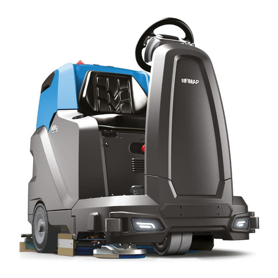
Page 3: Main Machine Components
MAIN MACHINE COMPONENTS The machine's main components are the following: Operator seat Recovery tank lid. Lateral scrubbing brush head (optional). Recovery tank. Scrubbing brush head. Solution tank. Squeegee body. Right hatch. Hour meter display – battery charge level. Left hatch. Headlights (optional). -
Page 4: Table Of Contents
CONTENTS MAIN MACHINE COMPONENTS .......... 3 10. CLEANING THE DEBRIS HOPPER (SWEEPING VERSION) ..19 CONTENTS ................4 11. EMPTYING THE SOLUTION TANK ........20 1. GENERAL SAFETY REGULATIONS ........ 5 12. CLEANING THE WATER SYSTEM FILTER ......20 2. SYMBOLS USED IN THE MANUAL ......... 9 13. -
Page 5: General Safety Regulations
1. GENERAL SAFETY REGULATIONS The following symbols are used to indicate any potentially hazardous situations. Always read this information carefully and take the necessary precautions to protect any people and/or objects that may be present. Operator cooperation is paramount for accident prevention. No accident prevention programme can be effective without the full cooperation of the person directly responsible for the machine's operation. - Page 6 WARNING: • Read all the relevant instructions carefully before performing any maintenance/repair operations. • Before using the battery charger, make sure that the frequency and the voltage values indicated on the machine's data plate coincide with the network's values. • Keep the battery charger's cable at a safe distance from any hot surfaces. •...
- Page 7 present while using this machine. • Be careful to avoid collisions with shelving or scaffolding, above all if there is a risk of objects falling from heights. • Do not place any liquid containers on the machine. • The machine must only be used under temperature conditions ranging from 0 °C to +40 °C. •...
- Page 8 • When disposing of consumable materials, observe the laws and regulations in force. Once the machine has reached the end of its service life, the materials contained within it must be disposed of in an appropriate manner, keeping in mind that the machine itself has been built using fully recyclable materials.
-
Page 9: Symbols Used In The Manual
Informs the operator that it is forbidden to tread on machine components, as this could lead to serious injury. Design by FIMAP Verona (Italy) Assembled in FIMAP Verona (Italy) Via Invalidi del Lavoro, 1 S. Maria di Zevio - Verona - Italy... -
Page 10: Technical Data
13. TECHNICAL DATA TECHNICAL DATA MMg 1SL [KMS] Cylindrical Orbital Rated machine power 2025 2140 2090 2090 Working capacity up to sq.m./h 4000 4500 5000 4500 Working width Working width with the lateral brush Squeegee width Central brush head brushes (number -Ø external bristles) No. -
Page 11: Symbols Used On The Machine
14. SYMBOLS USED ON THE MACHINE Main switch symbol: Warning label (versions without built-in battery charger): Applied to the control panel, positioned on the front of the machine, to Affixed to the machine in order to warn the operator to read the user and indicate the main switch. -
Page 12: Machine Preparation
15. Press the drive pedal (7) (Fig.10) to begin moving the machine. 16. MACHINE PREPARATION 16. Drive the machine down the ramp. 1. HANDLING THE PACKAGED MACHINE ATTENTION: during this operation, check there are no people or objects near the machine. The machine's overall weight including packaging is 000Kg. -
Page 13: Securing The Machine
CAUTION: the lifting hooks must not damage the blocks, connectors or cables. SECURING THE MACHINE NOTE: before inserting the batteries, remember to cover the terminals with a little grease to The procedure for securing the machine, thus allowing the operations to be performed under conditions of complete safety, is as follows: protect them against external corrosion. -
Page 14: Assembling The Squeegee
NOTE: carefully read the use and maintenance instructions of the battery charger that is used for charging. Remove the cap (4) from the battery charger socket (Fig.4). CAUTION: before connecting the batteries to the battery charger, make sure it is suitable for the batteries used. -
Page 15: Scrubbing Without Drying
The appliance will now begin to work with full efficiency until the battery is flat or until the detergent solution has finished. During the first few metres, check that there is sufficient solution. NOTE: If the drive pedal is released during the scrubbing without drying operation, the brush motor and the solenoid valve will be deactivated. -
Page 16: Reverse Gear
5. REVERSE GEAR 9. EMERGENCY BUTTON This machine is equipped with electronic traction control. To reverse, proceed as follows: If any problems are encountered during the work operations, press the emergency button (1) on the electrical system's cover carter (Fig.1). 1. -
Page 17: Lateral Brush 2Sl (Sweeping Version)
19. AT THE END OF THE WORK 13. LATERAL BRUSH 2SL (SWEEPING VERSION) If the lateral brushes need to be used during the floor scrubbing operations, and therefore with the brush At the end of the work, and before carrying out any type of maintenance, perform the following head in its working position, press the lateral brush head activation/deactivation button (1) on the left- operations: hand side of the steering column (Fig.1). -
Page 18: Emptying The Recovery Tank
1.EMPTYING THE RECOVERY TANK Proceed as follows to empty the recovery tank: 1. Take the machine to the maintenance area. 2. Make sure the machine has been secured (see the section titled “SECURING THE MACHINE”). CAUTION: users are advised to always wear protective gloves, to avoid the risk of serious injury to hands. -
Page 19: Cleaning The Lateral Brush (Scrubbing Version)
6. Clean the basket/filter (2) and the basket cover (3) under a jet of water. 6. CLEANING THE LATERAL BRUSH (SCRUBBING VERSION) NOTE: Use a spatula or brush to eliminate any dirt that is particularly difficult to remove. Careful cleaning of the brush guarantees better cleaning of the floor as well as a longer brush head gearmotor lifespan. -
Page 20: Emptying The Solution Tank
11.EMPTYING THE SOLUTION TANK CLEANING THE WATER SYSTEM FILTER Proceed as follows to empty the solution tank: In order to clean the water system's filter, do the following: 1. Take the machine to the maintenance area. 1. Take the machine to the maintenance area. 2. -
Page 21: Extraordinary Maintenance Work
6. With the brush head in its resting position, turn the knobs (4) that hold the left lateral carter (5) in 21. EXTRAORDINARY MAINTENANCE WORK place anti-clockwise (Fig.4). 7. Remove the left lateral carter (5) (Fig.5). 1. ASSEMBLING THE BRUSH HEAD BRUSHES (SCRUBBING VERSION) 8. -
Page 22: Replacing The Brush Head Brushes (Sweeping Version)
6. REPLACING THE BRUSH HEAD BRUSHES (SWEEPING VERSION) 9. REPLACING THE ABRASIVE PAD Ensuring the integrity of the brush will guarantee better floor cleaning results, and will extend the service Ensuring the good condition of the abrasive pad will guarantee better floor cleaning results, and will life of the brush head's gearmotor. -
Page 23: Adjustment Interventions
24. EC DECLARATION OF CONFORMITY ADJUSTING THE SQUEEGEE BODY'S RUBBER BLADES The undersigned manufacturer: FIMAP S.p.A. The careful adjustment of the squeegee unit rubber blades guarantees better cleaning of the floor. Via Invalidi del Lavoro, 1 To adjust the squeegee blades, proceed as follows:... -
Page 24: Troubleshooting
25. TROUBLESHOOTING This chapter lists the most common problems linked with the use of the machine. If you are unable to resolve the problems with the information given here, please contact your nearest assistance centre. PROBLEM POSSIBLE CAUSE SOLUTION The main switch is set to “0”. Make sure that the main switch is in its "I"... - Page 25 NOTES...
- Page 26 NOTES...
- Page 28 FIMAP S.p.A. - Via Invalidi del Lavoro, 1 - 37059 S. Maria di Zevio - Verona - Italy Tel. +39 045 6060411 – Fax +39 045 6060417 – E-mail:fimap@fimap.com www.fimap.com...
Need help?
Do you have a question about the MMg Series and is the answer not in the manual?
Questions and answers