
Related Manuals for Fimap MxL Pro Series


Summary of Contents for Fimap MxL Pro Series
- Page 1 MxL Pro PROFESSIONAL SCRUBBING MACHINES USE AND MAINTENANCE MANUAL ORIGINAL INSTRUCTIONS DOC. 10084108 - Ver. AA - 01-2019...
-
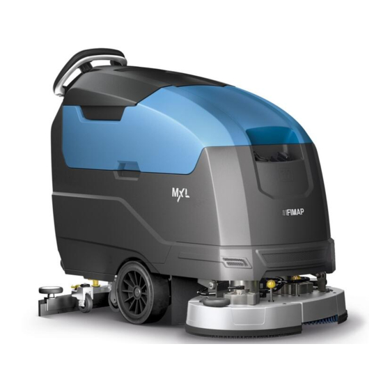
Page 3: Main Machine Components
4. Cover for FFM “FIMAP FLEET MANAGEMENT” SOS button 21. Solution tank filler tube cap. (Optional). 22. Cover cap for FFF “FIMAP FAST FILL” quick coupling kit 5. FFM “FIMAP FLEET MANAGEMENT” SOS button (Optional). (optional). 6. Control panel and control display. -
Page 4: Table Of Contents
CONTENTS MAIN MACHINE COMPONENTS ....................3 CONTENTS ..........................4 GENERAL SAFETY REGULATIONS ..................6 SYMBOLS USED IN THE MANUAL ..................6 PURPOSE AND CONTENT OF THE MANUAL .................7 STORING THE USE AND MAINTENANCE MANUAL ...............7 ON CONSIGNMENT OF THE MACHINE ...................7 INTRODUCTORY COMMENT ....................7 IDENTIFICATION DATA ......................7 TECHNICAL DESCRIPTION ......................7 INTENDED USE ..........................7... - Page 5 EXTRA BRUSH HEAD PRESSURE FUNCTION ....................22 SILENT-MAX FUNCTION ............................. 23 DETERGENT SOLUTION RECYCLING SYSTEM (FLR VERSIONS) ..............23 AUTOMATIC DETERGENT DOSING SYSTEM (FSS VERSIONS) ..............23 VACUUM WAND KIT ............................23 SPRAY GUN KIT ..............................24 ALARM SCREEN ..............................24 AUTOMATIC REQUEST FOR TECHNICAL ASSISTANCE (FFM VERSIONS) ..........
-
Page 6: General Safety Regulations
The descriptions contained in this document are not binding. The company therefore reserves the right to make any modifications at any time to elements, details, or accessory supply, as considered necessary for reasons of improvement or manufacturing/commercial requirements. The reproduction, even partial, of the text and drawings contained in this document is prohibited by law. The company reserves the right to make any technical and/or supply modifications. -
Page 7: Purpose And Content Of The Manual
PURPOSE AND CONTENT OF THE MANUAL The aim of this manual is to provide customers with all the information needed to use the machine in the safest, most appropriate and most autonomous way. This includes information concerning technical aspects, safety, operation, downtime, maintenance, spare parts and scrapping. The operators and qualified technicians must carefully read the instructions in this manual before carrying out any operations on the machine. -
Page 8: Serial Number Plate
5. The machine serial number. 6. The machine ID name. 7. The nominal power consumed by the machine (expressed in W). Design by FIMAP Verona (Italy) Assembled in FIMAP Verona (Italy) Via Invalidi del Lavoro, 1 S. Maria di Zevio - Verona - Italy 8. -
Page 9: Disposal
MxL 65 Bt MxL 75 Bt MxL 85 Bt MxL 70 Bts Unit of TECHNICAL DATA Measurement Rated machine power 1710 1710 1710 1610 Working capacity up to 17631 20591 22604 17362 Working width 25,8 30,1 33,1 25,4 Squeegee width 30,9 34,8 38,8... -
Page 10: Symbols Used On The Machine
SYMBOLS USED ON THE MACHINE SYMBOLS PRESENT ON THE REGISTRATION PLATE Direct current symbol: Used on the machine's registration plate to indicate that it is powered by a DC power supply. Battery symbol: Used on the machine's registration plate to indicate the maximum weight of the batteries used to power the machine (expressed in kg). -
Page 11: Symbols On The Control Panel
Moving brush hazard label: Used on the machine to warn the operator not to place his/her hands near the moving brush. Label warning about the risk of crushed hands: Indicates danger to hands due to crushing between two surfaces. Main switch symbol: Located near the control panel, to indicate the main key switch. -
Page 12: Preparation Of Machine
PREPARATION OF MACHINE HANDLING THE PACKAGED MACHINE The machine is contained in specific packaging, and since the packaging elements (plastic bags, staples, etc.) are a potential source of danger, they should not be left within the reach of children, disabled persons, etc. The machine's overall weight including packaging is 000Kg. -
Page 13: How To Move The Machine
7. Grip the handle (3) and turn the recovery tank until it reaches the working position. 8. The machine is fixed to the pallet by means of chocks, which block the wheels and brush head; remove these chocks. 9. Insert the starter key and turn on the machine; turn the main switch to the "I" position by turning the key (2) a quarter turn clockwise (Fig.5). 10. -
Page 14: Machine Safety
To fit the batteries inside the machine, contact an FIMAP assistance centre technician. The batteries should be connected so as to obtain a total voltage of 24V. WARNING: FIMAP declines all responsibility for any damage to property or injury persons in the event that the batteries are replaced by an unauthorized technician. -
Page 15: Assembling The Brush (Scrubbing Version)
ATTENTION: Before connecting the batteries to the battery charger, make sure that this is suitable for the batteries being used. NOTE: Carefully read the Use and Maintenance Manual of the battery charger to be used before carrying out the battery charge cycle. •... -
Page 16: Assembling The Squeegee Body
ASSEMBLING THE SQUEEGEE BODY For packaging reasons, the squeegee body comes disassembled from the machine. In order to mount it on the squeegee support, do the following: 1. Make sure the machine is in a safe condition (read “MACHINE SAFETY”). CAUTION: these operations must be carried out using protective gloves to avoid any possible contact with the edges or tips of metal objects. -
Page 17: Filling The Detergent Canister (Versions With Fss)
CAUTION: always use low-foam detergent. To avoid the production of foam, put a minimum quantity of anti-foam liquid in the recovery tank before starting to clean. Do not use pure acids. N.B.: to make it easier to measure the detergent on the cap/measuring device, there are notches indicating the detergent percentage quantities that can be used. -
Page 18: Preparing To Work
PREPARING TO WORK Before beginning to work, it is necessary to: 1. Make sure the recovery tank is empty. If this is not the case, empty it (read “EMPTYING THE RECOVERY TANK”). 2. Check that the quantity of detergent solution present in the solution tank is suitable for the type of work to be carried out. If this is not the case, fill the solution tank (see “THE SOLUTION TANK WITH WATER”... -
Page 19: Starting Work
STARTING WORK The machine can be used in the following work modes: • ECO-MODE, read the section “ECO-MODE”; • MANUAL MODE, read the section “MANUAL MODE”, • PROGRAM ZONE, read the section “PROGRAM ZONE MODE”. As an example, we will look at the program mode. To begin working in this mode, proceed as follows: 1. -
Page 20: Hour Meter
6. Lower the squeegee body and turn the squeegee control lever (3) in the direction of the arrow (Fig.5). The lever is located on the back of the machine. 7. When the dead man's lever (4) is pressed, the machine will begin to move. The lever is located underneath the control handlebars (Fig.6). N.B.: the gearmotor will only begin functioning, and the solenoid valve will only begin dispensing detergent solution, when the brush head body is in its working position. -
Page 21: Drying
5. When the dead man's lever (4) is pressed, the machine will begin to move. The lever is located underneath the control handlebars (Fig.6). N.B.: the gearmotor will only begin functioning, and the solenoid valve will only begin dispensing detergent solution, when the brush head body is in its working position. -
Page 22: Adjustment Of The Detergent Solution Flow
ADJUSTMENT OF THE DETERGENT SOLUTION FLOW To adjust the flow of detergent solution during work, proceed as follows: 1. During the first few working meters check that the amount of solution is sufficient to wet the floor, but not excessive to exit the splash guard. 2. -
Page 23: Silent-Max Function
SILENT-MAX FUNCTION This machine has a SILENT-MAX function for reducing the noise generated by the suction motor. To activate or deactivate this function, simply press the button (19) on the instrument panel for at least three seconds (Fig.4). N.B.: when the silent-max function is active, the relative LED (20) will light up on the control panel (Fig.4). DETERGENT SOLUTION RECYCLING SYSTEM (FLR VERSIONS) Upon request the machine can be fitted with a system that allows the detergent solution to be recycled so that productivity can be increased, since the number of stops needed to empty and fill the tanks is reduced. -
Page 24: Spray Gun Kit
The machine has an automatic service for activating an urgent technical assistance request. To activate this function, the operator must press the button (38) under the hatch (37) bearing the symbol “SOS” (Fig. 29). N.B.: in order to activate this urgent technical assistance request the machine needs to be equipped with the FIMAP FLEET MANAGEMENT kit. -
Page 25: Overflow Device
OVERFLOW DEVICE The machine is NOT equipped with an overflow device, because the volume of the recovery tank is greater than the capacity of the solution tank. In extraordinary cases, there is a mechanical device (float) under the recovery tank lid that, when the recovery tank is full, shuts off the air to the vacuum motor intake to protect it;... -
Page 26: Recommended Maintenance Operations
RECOMMENDED MAINTENANCE OPERATIONS INTERVAL MACHINE COMPONENTS PROCEDURE Clean the vacuum chamber; the squeegee rubber blades; the vacuum nozzle Squeegee (see “CLEANING THE SQUEEGEE BODY”). Empty the debris hopper and clean inside (see “CLEANING THE DEBRIS Debris hopper HOPPER (SWEEPING VERSION)”). Clean the brushes on the brush head body (see “CLEANING THE BRUSH HEAD BODY BRUSHES (SCRUBBING... -
Page 27: Cleaning The Squeegee Body
Before performing any routine or extraordinary maintenance operation, proceed as follows: 1. Take the machine to the maintenance area. N.B.: the place given over to this operation must comply with current environmental protection regulations. 2. Make sure the machine is in a safe condition (see chapter “MACHINE SAFETY MEASURES”). -
Page 28: Draining The Recovery Tank
7. See “INSTALLING THE BRUSH (SWEEPING VERSION)” for instructions on refitting the brushes in the brush head body. N.B.: Check that the bristles are not worn; in the event of excessive wear, replace the brush (the bristles should be at least 10 mm long). "REPLACING THE BRUSH (SWEEPING VERSION)"... -
Page 29: Extraordinary Maintenance Work
EXTRAORDINARY MAINTENANCE WORK REPLACING THE BRUSH (SCRUBBING VERSION) The good condition of the brush guarantees better cleaning of the floor, as well as a longer brush head gearmotor lifespan. To replace the brush, proceed as follows: 1. Go to the front of the machine. 2. -
Page 30: Adjustment Interventions
N.B.: Before using the machine, remember to adjust the squeegee body: see the section titled “ADJUSTING THE SQUEEGEE BODY'S RUBBER BLADES”. N.B.: It is recommended to replace both squeegee body blades in order to ensure good results when drying the floor. ADJUSTMENT INTERVENTIONS ADJUSTING THE SQUEEGEE BODY'S RUBBER BLADES The careful adjustment of the squeegee body rubber blades guarantees better cleaning of the floor. -
Page 31: Troubleshooting
MACHINE CODE BRISTLE NOTES 422189 PPL 0.3 BLUE BRUSH 422971 PPL 0.6 WHITE BRUSH MxL 65 Bt 422972 PPL 0.9 BLACK BRUSH 422981 ABRASIVE GREY BRUSH 422973 PAD HOLDER 414272 PPL 0.3 BLUE BRUSH 414270 PPL 0.6 WHITE BRUSH MxL 75 Bt 414273 PPL 0.9 BLACK BRUSH... - Page 32 PROBLEM POSSIBLE CAUSE SOLUTION The quantity of detergent solution in Check that the amount of detergent solution present in the machine's water NOT ENOUGH the water system is not sufficient for system is sufficient for the work to be carried out. DETERGENT the work to be carried out.
-
Page 33: Ec Declaration Of Conformity
EC DECLARATION OF CONFORMITY The undersigned manufacturer: FIMAP S.p.A. Via Invalidi del Lavoro, 1 37059 Santa Maria di Zevio (VR) declares under its sole responsibility that the products FLOOR SCRUBBING MACHINES mod. MxL 65 Bt Pro - MxL 75 Bt Pro - MxL 85 Bt Pro - MxL 70 Bts Pro comply with the provisions of Directives: •... - Page 34 The undersigned manufacturer: FIMAP S.p.A. Via Invalidi del Lavoro, 1 37059 Santa Maria di Zevio (VR) declares under its sole responsibility that the products FLOOR SCRUBBING MACHINES mod. MxL 65 Bt CB Pro - MxL 75 Bt CB Pro - MxL 85 Bt CB Pro - MxL 70 Bts CB Pro comply with the provisions of Directives: •...
- Page 36 FIMAP spa - Via Invalidi del Lavoro, 1 - 37059 S. Maria di Zevio - Verona - Italy Tel. +39 045 6060411 – Fax +39 045 6060417 – E-mail: fimap@fimap.com www.fimap.com...
Need help?
Do you have a question about the MxL Pro Series and is the answer not in the manual?
Questions and answers