Page 1
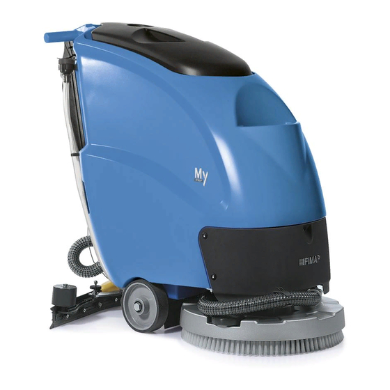
USE AND MAINTENANCE MANUAL MY50 B-E ED. 09-2011 ORIGINAL INSTRUCTIONS Doc. 10028647 AC Version...
Page 2
The descriptions contained in this document are not binding. The company therefore reserves the right to make any modifications at any time to elements, details, or accessory supply, as considered necessary for reasons of improvement or manufacturing/commercial requirements. The reproduction, even partial, of the text and drawings contained in this document is prohibited by law.
CONTENTS ON CONSIGNMENT OF THE MACHINE................................5 INTRODUCTORY COMMENT .................................... 5 INTENDED USE ........................................5 SERIAL NUMBER PLATE ....................................5 TECHNICAL DESCRIPTION....................................5 SYMBOLS USED ON THE MACHINE................................6 GENERAL SAFETY REGULATIONS................................. 8 MACHINE PREPARATION....................................9 1. HANDLING THE PACKAGED MACHINE .................................... 9 2.
Page 4
41. ELECTRIC SYSTEM SAFETY (E Version)..................................25 DISPOSAL ........................................26 CHOOSING AND USING THE BRUSHES ............................... 27 EC DECLARATION OF CONFORMITY................................28 EC DECLARATION OF CONFORMITY................................29...
In addition, it is not suitable as a means of transport for people or objects. TECHNICAL DESCRIPTION My50 B My50 E 230V My50 E 110V Working width Squeegee width...
SYMBOLS USED ON THE MACHINE Main switch symbol Used on the instrument panel, to indicate the switch for machine operation ON or OFF Symbol denoting suction motor Used on the instrument panel to indicate the switch that commands suction motor operation Brush release symbol Used on the instrument panel to indicate the button for automatic brush release Squeegee UP symbol...
Page 7
SYMBOLS USED ON THE MACHINE Battery charge level indicator Warning - high voltage 110-230 Volt Indicates the earth connection point of the electric system of the machine Indicates the maximum gradient...
GENERAL SAFETY REGULATIONS The regulations below must be carefully followed in order to avoid harm to the operator and damage to the machine. WARNING: Read the labels on the machine carefully. Do not cover them for any reason and replace them immediately if they become damaged. ...
MACHINE PREPARATION 1. HANDLING THE PACKAGED MACHINE The machine is contained in specific packaging with a pallet for the handling with fork trucks. The packages cannot be placed on top of each other. The total mass of the machine with packaging is 76.5 kg (without batteries). The dimensions of the packaging is as follows: My50 A: 1145 mm...
MACHINE PREPARATION 4. MACHINE'S REAR COMPONENTS The components at the rear of the machine are identified as follows: Brush operation / dead man's levers (located beneath the grip) Display for battery level / hour meter (battery-operated versions) Digital hour meter (electric versions) Main machine switch Suction motor switch Control lever for commanding the squeegee lifting cable...
MACHINE PREPARATION WARNING: you are advised to always wear protective gloves, to avoid the risk of serious injury to your hands WARNING: You are advised to only lift and move the batteries with lifting and transportation means suitable for the specific weight and size 8.
WARNING: you are advised to have the electric connections made by a qualified, FIMAP trained technician 9. BATTERY CHARGER CONNECTION (B VERSION, WITHOUT BC) In order not to cause permanent damage to the batteries it is essential to avoid their complete discharge: arrange the recharge within a few minutes of the switching on of the flashing "discharged batteries"...
Page 13
MACHINE PREPARATION To connect the batteries you must: 1. Make sure the dirty water recovery tank is empty; if necessary, empty it completely 2. Make sure the switch is in the OFF position 3. Take the machine to the designated machine storage place WARNING: park the machine indoors, on a flat and level surface;...
MACHINE PREPARATION 11. BATTERY CHARGE LEVEL INDICATOR (B VERSION) On the upper part of the display, you will see the total operating time. The line visualised shows the operating hours; the number consists of five figures, plus one figure after the point “.” to show the tenth of an hour.
MACHINE PREPARATION 15. FILLING THE SOLUTION TANK The solution tank can be filled in two different ways: 1. with a rubber tube, or buckets of water, using the filling nozzle (1) on the front part of the solution tank 2. with a rubber tube, using the rubber cap (2) on the rear part of the solution tank WARNING: make sure you keep the cap higher than the front filling nozzle By means of the transparent tube (3) and the level notches on the rear part of the solution tank, you can see how much water is in the tank.
MACHINE PREPARATION 17. REGULATING THE DETERGENT To regulate the flow of detergent solution, push the tap rod lever (1) on the rear left side of the solution tank (push the lever to increase the flow of solution onto the brush); when you press the dead man's levers, the brush is enabled and the machine begins to move.
MACHINE PREPARATION 20. ADJUSTING THE SQUEEGEE SUPPORT HEIGHT The height of the squeegee must be adjusted on the basis of the state of wear and tear of the rubber. Carry out the following operations for adjustment: 1. Unscrew the locking nut 2.
WORK 22. PREPARING TO WORK 1. Make sure the dirty water recovery tank is empty; if necessary, empty it completely 2. Check the main machine switch is set to “OFF” 3. Check the brush is correctly inserted 4. Connect the battery connector cable (1) to the main machine connector cable (2) (battery-operated versions) 5.
AT THE END OF THE WORK At the end of the work, and before carrying out any type of maintenance, perform the following operations: Turn off the detergent solution tap (1) on the rear part of the machine Lift the squeegee by inserting the squeegee cable tie-rod (2) in its seat on the back of the machine Deactivate the suction motor via the relevant switch (3) on the command panel in the rear part of the machine...
DAILY MAINTENANCE PERFORM ALL MAINTENANCE OPERATIONS IN SEQUENCE 25. CLEANING THE DIRTY WATER RECOVERY TANK Disconnect the tube (1) from its seat, unscrew the drainage cap, and empty the dirty water recovery tank. Remove the cover from the dirty water recovery tank (2). Clean and rinse the recovery tank and the suction pipe (connecting pipe between the squeegee and the tank).
DAILY MAINTENANCE 27. CLEANING THE SQUEEGEE The careful cleaning of the whole suction group ensures better drying and cleaning of the floor as well as greater duration of the suction motor. Proceed as follows for cleaning: 1. Check the main machine switch is set to “OFF” 2.
DAILY MAINTENANCE 29. CLEANING THE DETERGENT SOLUTION FILTER (OPTIONAL) 1. Make sure the dirty water recovery tank is empty; if necessary, empty it completely 2. Check the main machine switch is set to “OFF” 3. Disconnect the battery connector cable from the machine connector cable (battery-operated versions) 4.
WEEKLY MAINTENANCE 32. CLEANING THE SUCTION TUBE Whenever suction seems to be unsatisfactory, check that the suction tube is not obstructed. If necessary clean with a jet of water as follows: 1. Deactivate the main switch (1) by turning it to “OFF” 2.
EXTRAORDINARY MAINTENANCE 33. REPLACING THE FRONT SQUEEGEE RUBBER Suction will be poor and the machine will not dry perfectly if the front squeegee rubber is worn. Proceed as follows to replace: Deactivate the main switch by turning it to “OFF” Remove the squeegee from its support arm by unscrewing the handwheel Turn the wing nuts (1) to the horizontal position Remove the front rubber-pressing blades (2)
The machine is fitted with a thermal trip unit with manual reset, located in the rear part of the machine near the main switch. The brush motor is reset by pressing the thermal trip unit button. If the machine stops repeatedly in a short space of time, you must contact the FIMAP technical assistance centre.
DISPOSAL To dispose of the machine, take it to a demolition centre or an authorised collection centre. Before scrapping the machine it is necessary to remove and separate the following materials and send them to the appropriate collection centres in accordance with the environmental hygiene regulations currently in force: ...
Need help?
Do you have a question about the MY50 B and is the answer not in the manual?
Questions and answers