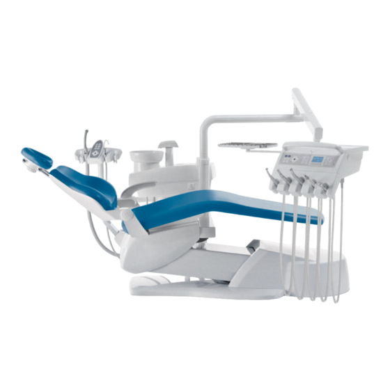
KaVo ESTETICA E30 Short Instructions For Use
Hide thumbs
Also See for ESTETICA E30:
- Instructions for use manual (134 pages) ,
- Care instructions (40 pages) ,
- Short instructions for use (34 pages)
Table of Contents
Advertisement
Advertisement
Table of Contents
Troubleshooting

Related Manuals for KaVo ESTETICA E30


Summary of Contents for KaVo ESTETICA E30
- Page 1 Short instructions for use ESTETICA E30...
- Page 2 Distributed by: Manufacturer: KaVo Dental GmbH Kaltenbach & Voigt GmbH Bismarckring 39 Bismarckring 39 D-88400 Biberach D-88400 Biberach Tel. +49 7351 56-0 www.kavo.com Fax +49 7351 56-1488...
-
Page 3: Table Of Contents
Table of contents Table of contents Controls ............................2 Dentist element TM table ..................... 2 Dentist element S table ......................2 Assistant element ......................... 3 Groups of keys ........................3 Foot control .......................... 6 Moving the patient chair ......................... 7 Positioning the dental chair manually ................... -
Page 4: Controls
Controls 1 Controls CAUTION These brief instructions for use only contain the essential operating functions. They do not substitute for the instructions for use and care that are part of the scope of delivery. ▶ Take note of the instructions for use and care that are part of the scope of de‐ livery. -
Page 5: Assistant Element
Controls 1.3 Assistant element A Group of keys for hygiene C Group of keys for the timer B Group of keys for illumination D Group of keys for the dental chair 1.4 Groups of keys Group of keys for the dental chair The keys of the assistant unit each have two functions and show two symbols. - Page 6 Controls Assistant unit key Dentist unit key Labelling "Backrest down" key "AP 1" key (automatic position 1) "Backrest up" key "AP 2" key (automatic position 2) "Collapsed position" key Group of keys for illumination/handpieces Name Control element Dentist element and assistant el‐ ement "Operating light"...
- Page 7 Controls Name Control element "Bell" key Dentist element and assistant element "Intensive disinfection" key Assistant element (unassigned key) "HYDROclean" key Assistant element (unassigned key) Group of keys for the menu Group of keys for the menu ① Menu function selection keys ②...
-
Page 8: Foot Control
Controls 1.5 Foot control Item Name with mounted with removed handpiece handpiece ① "LP/preselected spray" foot- Drives dental chair to previ‐ optional. Sets the spray pre- operated button ous position selection. ② U-shaped switch Switches the foot-operated buttons to the "Chair motion" function. -
Page 9: Moving The Patient Chair
Moving the patient chair 2 Moving the patient chair 2.1 Positioning the dental chair manually Function The chair moves up. The chair moves down. The backrest moves upward. The backrest moves downward. 2.2 Positioning the patient chair with the foot control See also: 1.5, Foot control, Page 6 2.3 Automatic positioning of patient chair Recalling automatic position through the dentist element... - Page 10 Moving the patient chair The LEDs of the "AP 0", " AP 1", " AP 2", "SP", and "LP" keys flash for approxi‐ mately four seconds. ▶ During these four seconds, briefly press the "AP 0", " AP 1", " AP 2", "SP" or "LP" key.
-
Page 11: User Menu
User menu 3 User menu The following options can be opened in the user menu: Option Function Description Users Set number of users. Tumbler Set tumbler filling time. Bowl Set bowl rinsing time. Handpiece light Set cold light afterglow period. ENDO Set ENDO holder. -
Page 12: Selecting And Setting An Option
User menu Option 1: Set number of users ▶ Press button "S1", "S2", "S3". Users 1, 2 or 3 will be selected. ▶ Press "S4" button. 2. level is displayed. Users 4 – 6 can be selected. ▶ Press button "S1", "S2", "S3". Users 4, 5 or 6 will be selected. -
Page 13: Standby Menu
Standby menu 4 Standby menu The stand-by menu is used to start the device. The device switches to the stand-by menu upon closing of the handpiece and endo menus. ▶ Press the "Next" key (S4) to start-up the user menu. The user menu displays options and parameters. -
Page 14: Setting The Timer
Setting the timer 5 Setting the timer 5.1 Select the timer time ▶ Press the "Timer" key briefly to start or stop the timer. LED flashes while the timer counts down. 5.2 Set the timer time ▶ Press the "Timer" key for an extended period of time to start the timer programming mode. The pro‐ gramming mode can be started in the stand-by menu only. -
Page 15: Setting The Handpieces
Setting the handpieces 6 Setting the handpieces 6.1 Adjusting functions ▶ Settings can be changed using the corresponding keys on the control panel or on the foot control. Motor speed is set with the foot control only. The direction of motor rotation, cooling status and light intensity are set with the foot control or the control keys. -
Page 16: Turbine
Setting the handpieces ▶ Press the button for "light intensity" (S4) to set the light intensity from 1 to 9 (ring counter). Setting the direction of motor rotation Note The rotational direction of the motor can only be changed when the motor is at rest. ▶... -
Page 17: Kl 703 Led In Endo Mode (Optional Accessories)
Setting the handpieces The following settings can be changed with the foot control: ▪ Direction of motor rotation ▪ Speed ▪ Cold light intensity ▪ Spray status ▪ Light on/off 6.4 KL 703 LED in ENDO mode (optional accessories) Note The functions of the ENDO menu are available only if an ENDO dongle is present. - Page 18 Setting the handpieces Setting options ▶ Press the "S4" key to select the ENDO options menu. Parameters Values Transmission factor 1:1, 3:1 Parameter memory P1,P2,P3,P4,P5,P6 Torque mode TQ-Ctrl, Autoreverse, AutoRev/Forw. Direction of motor rotation R, L Speed 100 to 6,000 rpm Torque Transmission ratio 1:1: 0.15 to 2.50 Ncm Transmission ratio 3:1: 0.4 to 8.0 Ncm...
- Page 19 Setting the handpieces The torque can be changed as follows: ▪ in steps of 0.05 Ncm: in the range from 0.4 Ncm to 8 Ncm ▪ in steps of 2%: in the range from 1 % to 100 % Torque mode Three different torque modes are available: ▪...
-
Page 20: Operate Handpieces With The Foot Control
Operate handpieces with the foot control 7 Operate handpieces with the foot control ▶ Remove the handpiece (such as turbine, motor) from the holder. The handpiece is active. ▶ Press the foot pedal. The removed handpiece runs at the set speed or intensity. ▶... -
Page 21: Hygiene
During normal operation of the treatment centre, the continuous disinfection function (available with water bottle kit and added disinfectant KaVo OXYGENAL 6) ensures continuous germ reduction of the water-supplying systems. Manual rinsing and manual intensive disinfection facilitate the rinsing and disinfection of the water- supplying system. -
Page 22: Conditioning The Suction System
▶ After the time of exposure, e.g. after the weekend, actuate the tumbler for 15 seconds and rinse each handpiece (without attachment handpieces or cannulas) for 20 seconds. See also: Servicing Instructions ESTETICA E30 8.4 Conditioning the suction system Note Clean the suction hoses after each treatment and disinfect them with DEKASEPTOL Gel daily. -
Page 23: Replenishing Oxygenal
Hygiene Without air jet suction system (Venturi) ▶ Aspirate another tumbler of cold water with each suction hose. ▶ Finally, aspirate another dose of DEKASEPTOL Gel and allow it to act. With/without air jet suction system (Venturi) ▶ Place the suction hoses in the holder. DEKASEPTOL Gel Basis Set DEKASEPTOL Gel replacement canister Mat. - Page 24 ▶ Remove the protective hose from the tube of the KaVo OXYGENAL 6 dosing facility. ▶ Guide the tube through the orifice of the coarse sieve of the KaVo OXYGENAL 6 bottle. ▶ Screw the KaVo OXYGENAL 6 dosing facility tightly to the KaVo OXYGENAL 6 bottle.
- Page 25 ▶ Proceed like for filling the water bottle, but use a different dose of KaVo OXYGENAL 6. ▶ Fill the four-fold dose of KaVo OXYGENAL 6 (equivalent to 20 ml) in the intensive disinfection bot‐ tle. Make sure that the spout of the KaVo OXYGENAL 6 dosing facility (nose) is situated right above the opening of the intensive disinfection bottle.
-
Page 26: Troubleshooting / Warning Signals
Troubleshooting / warning signals 9 Troubleshooting / warning signals 9.1 Safety shut-off Pos. no. Safety switch-off actuated LED on assistant element LED on dentist element ① Bracket on the foot control ② Assistant element ③ Backrest ④ Kickplate ⑤ Seat For right/left conversion with bench removed ▶... -
Page 27: Troubleshooting
Troubleshooting / warning signals 9.2 Troubleshooting Malfunction Cause Remedy Nothing works. Main switch is off. ▶ Turn on the main switch. Main service fuse interrupted the ▶ Unplug the unit from the electric circuit. mains. ▶ Check and replace, if re‐ quired, the main service fuse. -
Page 28: Service And Error Messages In The Stand-By Menu
Troubleshooting / warning signals Malfunction Cause Remedy The main water valve in the of‐ ▶ Open main valve. fice is closed. The compressor is not turned ▶ Turn on the compressor. No water in the tumbler and spit‐ Water bottle is empty. ▶... - Page 29 Troubleshooting / warning signals Settings Previous message Next message Switch to stand-by menu Error messages in the status display Malfunction Cause Remedy Display shows: ID 64 Water is shut off. ▶ Turn water on. Water works leaks strongly. ▶ Call a technician. Water works malfunction Display shows: ID 65 Safety switch of bowl suction...
Need help?
Do you have a question about the ESTETICA E30 and is the answer not in the manual?
Questions and answers