KaVo ESTETICA E50 Life Instructions For Use Manual
Hide thumbs
Also See for ESTETICA E50 Life:
- Instructions for use manual (162 pages) ,
- Care instructions (58 pages) ,
- Short instructions for use (42 pages)
Table of Contents
Advertisement
Quick Links
Advertisement
Table of Contents

Related Manuals for KaVo ESTETICA E50 Life


Summary of Contents for KaVo ESTETICA E50 Life
- Page 1 Instructions for use ESTETICA E50 Life...
- Page 2 Distributed by: Manufacturer: KaVo Dental GmbH Kaltenbach & Voigt GmbH Bismarckring 39 Bismarckring 39 D-88400 Biberach D-88400 Biberach Phone +49 (0) 7351 56-0 www.kavo.com Fax +49 (0) 7351 56-1488...
-
Page 3: Table Of Contents
Instructions for use ESTETICA E50 Life Table of contents Table of contents 1 User instructions............................... 7 1.1 User guide..............................7 1.1.1 Abbreviations..........................7 1.1.2 Symbols............................7 1.1.3 Target group..........................7 1.2 Service..............................7 1.3 Terms and conditions of warranty......................8 1.4 Transportation and storage........................ - Page 4 Instructions for use ESTETICA E50 Life Table of contents 4.2 Adjusting the dental chair........................44 4.2.1 Adjusting the arm rest (optional)....................44 4.2.2 Adjust head rest......................... 45 4.2.3 Positioning the dental chair manually..................47 4.2.4 Automatic positioning of dental chair..................48 4.2.5...
- Page 5 Instructions for use ESTETICA E50 Life Table of contents 4.11 Using the KL 703 LED / KL 702 in ENDO mode (optional accessory)..........101 4.11.1 General information......................... 101 4.11.2 Open ENDO mode........................102 4.11.3 Change settings in the option menu..................103 4.11.4 Set parameters........................
- Page 6 Instructions for use ESTETICA E50 Life Table of contents 10.1 Electromagnetic Transmissions......................149 10.2 Resistance to electromagnetic interference..................149 10.3 Recommended safe distance between portable and mobile HF telecommunications equipment and the treatment unit............................150 10.4 Immunity to electromagnetic interference..................... 151...
-
Page 7: User Instructions
Instructions for use ESTETICA E50 Life 1 User instructions | 1.1 User guide 1 User instructions 1.1 User guide Requirement Read these instructions prior to first use to avoid misuse and prevent damage. 1.1.1 Abbreviations Abbre‐ Explanation viation Instructions for use... -
Page 8: Terms And Conditions Of Warranty
1 User instructions | 1.3 Terms and conditions of warranty 1.3 Terms and conditions of warranty KaVo provides the final customer with a warranty that the product cited in the hand‐ over certificate will function properly and guarantees zero defects in the material or... -
Page 9: Information On The Packaging: Storage And Transportation
(in accordance with the General German Freight Forwarders´ Terms and Conditions, Art. 28) Outside Germany Note KaVo shall not be held liable for damage arising from transportation. The shipment must be checked on arrival. If the packaging is visibly damaged on delivery, please proceed as follows: 1. - Page 10 Instructions for use ESTETICA E50 Life 1 User instructions | 1.4 Transportation and storage Permissible stacking load Temperature range Humidity Air pressure 10 / 154...
-
Page 11: Safety
The KaVo equipment system is a dental treatment unit in accordance with ISO 7494 with a dental chair in accordance with ISO 6875. This KaVo product is designed for use in dentistry only and may only be used by trained medical personnel. Any other type of use is not permitted. - Page 12 KaVo, provided: ▪ installation, instructions, expansions, adjustments, changes or repairs were carried out by technicians trained by KaVo or third parties authorised by KaVo, or by the personnel of authorised distributors. ▪ the unit was operated in accordance with the instructions for use, care and instal‐...
- Page 13 The MULTIflex couplings, the current K/KL motors, and the ultrasonic scaler hoses of KaVo are equipped as standard with a protective device to prevent treatment wa‐ ter from being drawn back into the treatment centre via the handpieces. If products from other manufacturers are used at the standardised interfaces, it must be ensur‐...
-
Page 14: Product-Specific
Designated use and target group KaVo is designed for dental treatment of children and adults. The KaVo equipment system is a dental treatment unit in accordance with ISO 7494 equipped with a dental chair in accordance with ISO 6875. KaVo three-way and multi‐... -
Page 15: Safety Instructions
When connecting IT equipment to the the medial electrical system, observe EN 60601-1. Note Charge the wireless foot control with the charger supplied by KaVo only. Note The foot control charger may only be used indoors and must be protected from moisture. - Page 16 Instructions for use ESTETICA E50 Life 2 Safety | 2.3 Safety instructions WARNING Injury or damage from damaged functional parts. Damage to functional parts can cause further damage or personal injury. ▶ Check the device, electrical cables and any accessories for possible damage to the insulation and replace if necessary.
-
Page 17: Product-Specific
Instructions for use ESTETICA E50 Life 2 Safety | 2.3 Safety instructions 2.3.2 Product-specific WARNING Injury or infection hazard from laid down instruments. Given the arrangement of the instruments, injury or infections in the hand and under‐ arm can arise when reaching for the tray holder or operating device. Increased risk of infection from diseased patients. - Page 18 Instructions for use ESTETICA E50 Life 2 Safety | 2.3 Safety instructions CAUTION Electrical power. Electrical shock. ▶ Set up the external PC outside of the patient environment keeping a minimal dis‐ tance of 1.5 m. ▶ Connect the PC and equipment connected to the PC in accordance with IEC 60601-1 / 60950.
- Page 19 Instructions for use ESTETICA E50 Life 2 Safety | 2.3 Safety instructions CAUTION Risk of injury and material damage from incorrect use of the charger for the wireless foot control. Personal injuries, damage to the wireless foot control or the charger.
-
Page 20: Product Description
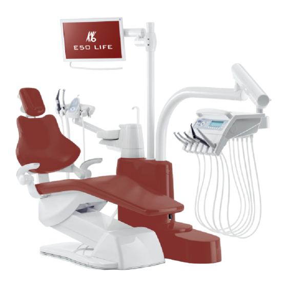
Instructions for use ESTETICA E50 Life 3 Product description | 3.1 Treatment unit versions 3 Product description 3.1 Treatment unit versions 3.1.1 KaVo ESTETICA E50 Life TM 3.1.2 KaVo ESTETICA E50 Life S 20 / 154... -
Page 21: Patient Chair Standard And Compactchair
Instructions for use ESTETICA E50 Life 3 Product description | 3.2 Patient chair Standard and COMPACTchair 3.2 Patient chair Standard and COMPACTchair ① Headrest ② Backrest ③ Chair base ④ Seat ⑤ Arm rest (optional) 21 / 154... -
Page 22: Device Body With Patient Unit
Instructions for use ESTETICA E50 Life 3 Product description | 3.3 Device body with patient unit 3.3 Device body with patient unit ① Patient element ② Unit body The central control is housed in the unit body. ③ Pressurised water bottle ④... - Page 23 Instructions for use ESTETICA E50 Life 3 Product description | 3.3 Device body with patient unit E50 Life with Centramat ① Patient element ② Unit body The central control is housed in the unit body. ③ Centramat ④ Spittoon bowl (supplementary equipment) ⑤...
-
Page 24: Dentist Unit Versions
Instructions for use ESTETICA E50 Life 3 Product description | 3.4 Dentist unit versions 3.4 Dentist unit versions 3.4.1 TM table ① Handle ② Three-function handpiece or multi‐ functional handpiece ③ Turbine (multiflex coupling) ④ INTRA LUX motor KL 703 or INTRA LUX motor KL 701 ⑤... -
Page 25: S Table
Instructions for use ESTETICA E50 Life 3 Product description | 3.4 Dentist unit versions 3.4.2 S table Note The holder assignment and arrangement of the instruments can be changed as needed and does not have to follow the picture. ① Small X-ray image viewer ②... -
Page 26: Assistant Element - Versions
Instructions for use ESTETICA E50 Life 3 Product description | 3.5 Assistant element – Versions 3.5 Assistant element – Versions 3.5.1 Standard assistant unit ① Three-function or multifunctional ② Spray mist suction handpiece ③ Control element ④ Saliva ejector ⑤ Satelec Mini LED ⑥... -
Page 27: Assistant Element Right, Left (Optional)
Instructions for use ESTETICA E50 Life 3 Product description | 3.5 Assistant element – Versions 3.5.2 Assistant element right, left (optional) Assistant element right, left with height adjustment (optional) ① Three-function handpiece ② Spray mist suction ③ Control element ④ Saliva ejector ⑤... -
Page 28: Three Function Handpiece (3F Handpiece)
Instructions for use ESTETICA E50 Life 3 Product description | 3.6 Three function handpiece (3F handpiece) 3.6 Three function handpiece (3F handpiece) ① MF handpiece hose ② Gripping sleeve ③ Media buttons (air/water) ④ Labelled blue: Three-function hand‐ piece (3F handpiece) ⑤... -
Page 29: Controls
Instructions for use ESTETICA E50 Life 3 Product description | 3.8 Controls 3.8 Controls 3.8.1 Dentist's unit TM table Dentist's unit Group of keys for the dental chair Group of keys for illumination Group of keys for hygiene Group of keys for menu selection... -
Page 30: Assistant Unit
Instructions for use ESTETICA E50 Life 3 Product description | 3.8 Controls 3.8.3 Assistant unit Group of keys for hygiene Group of keys for illumination Group of keys for the timer Group of keys for the dental chair 3.8.4 Groups of keys Group of keys for the dental chair The keys of the assistant unit each have two functions and show two symbols. - Page 31 Instructions for use ESTETICA E50 Life 3 Product description | 3.8 Controls Assistant element key Dentist element key Name "Backrest up" key "AP 2" key (automatic position 2) "Collapsed position" key Group of keys for illumination Name Control element "Operating light" key dentist element only "Operating light dimming"...
- Page 32 Instructions for use ESTETICA E50 Life 3 Product description | 3.8 Controls Group of keys for the timer Name Control element "Additional motor drives" Dentist element only "Remote Control" key Dentist element only "Timer 1" key Dentist element and assistant element "Timer 2"...
-
Page 33: Foot Control
Instructions for use ESTETICA E50 Life 3 Product description | 3.8 Controls 3.8.5 Foot control The footswitches of the foot control have two functions. The functions of the foot‐ switches depend on if an instrument is mounted or removed. Foot control Premium and wireless foot control | Foot control Standard... -
Page 34: Rating Plate And Identification Plate
Instructions for use ESTETICA E50 Life 3 Product description | 3.9 Rating plate and identification plate 3.9 Rating plate and identification plate Rating plate Rating plates inside and outside Internal attachment site for rating plate 400s Outside attachment site for rating plate... - Page 35 Instructions for use ESTETICA E50 Life 3 Product description | 3.9 Rating plate and identification plate Serial number Read and take note of the content of accompanying documents Please note the instructions for use Follow the instructions for use! Type B applied part...
- Page 36 Instructions for use ESTETICA E50 Life 3 Product description | 3.9 Rating plate and identification plate Rating plate and dentist element ID Site of attachment of nameplate and type BF applied parts ID on dentist element Nameplate dentist element (e.g. table TM) / marking of the application parts of type BF...
- Page 37 Instructions for use ESTETICA E50 Life 3 Product description | 3.9 Rating plate and identification plate Labelling and marking of the three-function handpiece and multifunctional handpiece Company logo of the manufacturer Serial number CE mark according to 93/42/EEC medical devices...
-
Page 38: Technical Data
Instructions for use ESTETICA E50 Life 3 Product description | 3.10 Technical data 3.10 Technical data Drilling template and setup plan Installation plan (Mat. no. 3.002.4533) 2 sheets each right-handed and 2 sheets left-handed Installation plan with COMPACTchair 2 sheets each right-handed and 2 sheets (Mat. - Page 39 Instructions for use ESTETICA E50 Life 3 Product description | 3.10 Technical data Wireless foot control Frequency band ISM 2.4 GHz Radiated output max. 0 dBm e.i.r.p. (max. 1 mW) Supply rechargeable battery Type Varta PoLiFlex PLF503759 Number of cells...
- Page 40 In conjunction with the "DVGW water block with integrated water disinfection" a wa‐ ter disinfection unit is installed in dental units from KaVo. The disinfectant OXY‐ GENAL 6 is continually added to the water in a concentration which is harmless for persons, but hygienically effective to maintain the quality of the treatment water.
- Page 41 ▶ With regard to the "Water block, compact" assembly kit, please note that no disin‐ fection facility is installed in the unit, and take appropriate safeguards. KaVo rec‐ ommends to use the "Water block DVGW with integrated water disinfection facility in combination with KaVo OXYGENAL 6 (Mat.
- Page 42 Diameter of the suction connection 40 mm Above-floor suction connection 20 mm The values apply to the KaVo measuring set (Mat. no. 0.411.8500). Central Dekaseptol supply (optional) 2 - 5 bar by means of ball valve, to be pro‐ vided by customer (John Guest PPMSV040808W) 0.005 - 0.15 l/min...
- Page 43 Instructions for use ESTETICA E50 Life 3 Product description | 3.10 Technical data Operating environment WARNING Inappropriate operating conditions. Impairment of the electrical safety of the device. ▶ It is essential to comply with the operating conditions specified in the "Technical Specifications"...
-
Page 44: Operation
Instructions for use ESTETICA E50 Life 4 Operation | 4.1 Switching the device on and off 4 Operation 4.1 Switching the device on and off Note Always switch the machine off before leaving the office. E50 Life without/with Centramat ▶ Switch on the device using the main switch. -
Page 45: Adjust Head Rest
Instructions for use ESTETICA E50 Life 4 Operation | 4.2 Adjusting the dental chair CAUTION The patient's hands are in a bad position when the chair is rising Danger of crushing fingers between the backrest and armrest. ▶ Make sure that the patient is sitting in the right position (especially children). - Page 46 Instructions for use ESTETICA E50 Life 4 Operation | 4.2 Adjusting the dental chair ▶ Push in or pull out the headrest depending on the patient's size. ▶ To swing the headrest, turn the locking dial to the left, move the headrest into po‐...
-
Page 47: Positioning The Dental Chair Manually
Instructions for use ESTETICA E50 Life 4 Operation | 4.2 Adjusting the dental chair Note The service technician can adjust the braking force. ▶ Press the lock button and swing the headrest into the desired position. When swinging the headrest back into position, make sure that there is nothing between the area A and head cushion. -
Page 48: Automatic Positioning Of Dental Chair
Instructions for use ESTETICA E50 Life 4 Operation | 4.2 Adjusting the dental chair Function The chair moves up. The chair moves down. The backrest moves upward. The backrest moves downward. ▶ Press the related key. ð The chair or backrest moves in the desired direction. - Page 49 Instructions for use ESTETICA E50 Life 4 Operation | 4.2 Adjusting the dental chair CAUTION Risk of injury when moving the patient or patient chair. The patient or treatment personnel can be pinched or crushed. ▶ Position all moving parts, such as dentist element, assistant element, operating light, screens, etc., outside the collision range when you move the patient or pa‐...
- Page 50 Instructions for use ESTETICA E50 Life 4 Operation | 4.2 Adjusting the dental chair Recalling automatic positions with the dentist unit The following keys can be used to recall saved chair positions. Operation Move to the rinsing position. The last position before actuating the SP is assumed.
- Page 51 Instructions for use ESTETICA E50 Life 4 Operation | 4.2 Adjusting the dental chair ð The LEDs of the "AP 0", " AP 1", " AP 2", "SP", and "LP" keys flash for approxi‐ mately four seconds. ▶ During these four seconds, briefly press the "AP 0", " AP 1", " AP 2", "SP" or "LP"...
- Page 52 Instructions for use ESTETICA E50 Life 4 Operation | 4.2 Adjusting the dental chair ▪ "Blown air" foot switch: automatic position "SP" (rinsing position) Move the chair when the instrument is mounted ▶ Press the "SP" foot switch. ▶ Press the "LP" foot switch.
-
Page 53: Safety Shut-Off
Instructions for use ESTETICA E50 Life 4 Operation | 4.2 Adjusting the dental chair ▶ Hold down the foot pedal and foot-operated button "SP", and simultaneously press any button for an automatic position ("AP 0", "AP 1", "AP 2" or "SP") on the dentist or assistant unit until you hear a beep. - Page 54 Instructions for use ESTETICA E50 Life 4 Operation | 4.2 Adjusting the dental chair Patient chair Standard NOTICE Overheating of the drives. Material damage to the patient chair. ▶ Note the maximal on-time of 2 minutes without interruption (10 %).
- Page 55 Instructions for use ESTETICA E50 Life 4 Operation | 4.2 Adjusting the dental chair Patient chair COMPACTchair Safety shutoff for the COMPACTchair patient chair ① Patient element pivoted over dental ② Assistant element chair ③ Backrest ④ Bracket on the foot control ⑤...
- Page 56 Instructions for use ESTETICA E50 Life 4 Operation | 4.2 Adjusting the dental chair Note The chair's position cannot be changed with the key wheels when a safety shutoff is activated. ▶ To deactivate an activated safety shutoff, remove the triggers from the to the range of movement of the stool.
-
Page 57: Moving The Patient Chair
Instructions for use ESTETICA E50 Life 4 Operation | 4.3 Moving the patient chair 4.3 Moving the patient chair Patient chair Standard Patient chair COMPACTchair 4.4 Moving the dentist unit CAUTION Damage from overloading the dentist element. Exceeding the maximum weight of more than 2 kg by adding handpieces, accesso‐... -
Page 58: Moving The Dentist Unit Tm
Instructions for use ESTETICA E50 Life 4 Operation | 4.4 Moving the dentist unit Note Do not pull the dentist unit by the instrument hose. ▶ To adjust the height of the dentist unit, release the brake, adjust the height, and reset the brake. -
Page 59: Moving The Patient Unit
Instructions for use ESTETICA E50 Life 4 Operation | 4.5 Moving the patient unit CAUTION Damage from overloading the dentist element. Exceeding the maximum weight of more than 2 kg by adding handpieces, accesso‐ ries, etc., can cause damage. ▶ Do not overload the dentist element! Dentist unit S 4.5 Moving the patient unit... -
Page 60: Moving The Assistant Element
Instructions for use ESTETICA E50 Life 4 Operation | 4.6 Moving the assistant element 4.6 Moving the assistant element 4.6.1 Adjusting the height of the standard assistant element The assistant unit can be vertically positioned in four levels. ▶ To set a higher level, pull the assistant unit upward gently until it audibly locks in place. - Page 61 Instructions for use ESTETICA E50 Life 4 Operation | 4.6 Moving the assistant element CAUTION Material damage caused by overloading. ▶ Do not rest your foot near the pivot point and/or transverse arm of the assistant element. Pivoting range of assistant element r, l (optional) ▶...
-
Page 62: Using Functions Through The Menu
Instructions for use ESTETICA E50 Life 4 Operation | 4.7 Using functions through the menu Adjusting the height of the assistant element right, left (optional) Note Handpieces may drop out of the holders while the assistant element is being moved, especially during adjustment of the height. In order to prevent handpieces from being damaged, make sure that no handpiece drops down while you move the assistant element. - Page 63 Instructions for use ESTETICA E50 Life 4 Operation | 4.7 Using functions through the menu Option Function Description Equipment profile ▪ Save equipment profile from treat‐ ment unit to SD card. ▪ Save equipment profile from SD card to treatment unit.
- Page 64 Instructions for use ESTETICA E50 Life 4 Operation | 4.7 Using functions through the menu Navigation in the user menu Function keys Description Switch option to "Return" Switch option to "Forwards" Move cursor (if possible) Reduce set value Increase set value Exit the user menu and save the settings.
- Page 65 Instructions for use ESTETICA E50 Life 4 Operation | 4.7 Using functions through the menu Option 4: Set LUX afterglow period ▶ Press the "increase value" or "reduce value" key to set the LUX afterglow period between 0 to 10 seconds. The default value is 3 seconds.
- Page 66 Instructions for use ESTETICA E50 Life 4 Operation | 4.7 Using functions through the menu Option 9: Set display mode for time of day and date Option "Display mode for time of day / Date", "Time of day only" setting Option "Display mode for time of day / Date", "Time of day only <no sec>"...
-
Page 67: Standby Menu
Instructions for use ESTETICA E50 Life 4 Operation | 4.7 Using functions through the menu Option 12: Setting dimming mode for the LED lamp. Note The "Set dimming mode for LED lamp" option is only indicated if an LED lamp is installed on the treatment centre and has been activated by the technician in serv‐... - Page 68 Instructions for use ESTETICA E50 Life 4 Operation | 4.7 Using functions through the menu The unit automatically switches to the Standby menu when the Instrument menu and Multimedia menu are closed. Select function The display shows display fields with symbols for the operating functions.
- Page 69 Instructions for use ESTETICA E50 Life 4 Operation | 4.7 Using functions through the menu Note Level switching is deactivated using the same key combination as activation. ▶ To select a level, briefly press the selection button for "Preselect level".
-
Page 70: Using The Memodent Menu
Instructions for use ESTETICA E50 Life 4 Operation | 4.7 Using functions through the menu ▶ Press the "S2" selection key ① to display status messages. ▶ Press the selection keys "+" ② and "-" ① to switch between multiple status mes‐... -
Page 71: Changing The Settings For Intra Lux Motors Kl 703 Led / Kl 701 And Comfortdrive
Instructions for use ESTETICA E50 Life 4 Operation | 4.7 Using functions through the menu Setting the speed ▶ Press the key for "Decrease value" to decrease the speed. ▶ Press the "Increase value" key to increase the speed. ð... -
Page 72: Changing Piezoled Settings In The Memodent Menu
Instructions for use ESTETICA E50 Life 4 Operation | 4.7 Using functions through the menu The settings for the speed, cooling and cold light are made in the same manner as with the turbine. See also: 2 Changing the turbine settings in the MEMOdent menu, Page 0 ▶... - Page 73 Instructions for use ESTETICA E50 Life 4 Operation | 4.7 Using functions through the menu ð The following is shown on the display. ▶ Briefly press "Preselect level" button to select the level. ▶ Press "Preselect level" button for 4 seconds.
-
Page 74: Changing Settings For The Multifunctional Handpiece In The Memodent Menu
Instructions for use ESTETICA E50 Life 4 Operation | 4.7 Using functions through the menu Dosing the amount of spray water CAUTION Lack of working tip cooling. Heat damage to tooth or handpiece. ▶ Never work under dry conditions, except in case of tips designed for these condi‐... -
Page 75: Use The Timer
Instructions for use ESTETICA E50 Life 4 Operation | 4.7 Using functions through the menu See also: 2 Changing the turbine settings in the MEMOdent menu, Page 0 ▶ Briefly press "Preselect level" button to select the level. ▶ Remove the multifunction handpiece from the holder. -
Page 76: Using The Conexiocom Menu
In order to use the function, the unit must have ac‐ cess to the data of the KaVo Software "CONEXIO" software. For details on the config‐ uration, please refer to the "CONEXIO" installation instructions. - Page 77 Instructions for use ESTETICA E50 Life 4 Operation | 4.7 Using functions through the menu The CONEXIOcom menu is opened automatically for recording of images or videos as soon as a device (DIAGNOcam U, ERGOcam One) is taken out. To close CONEXIOcom: Replace the active device to its holder or close the CONEX‐...
-
Page 78: Using Function Through The Dentist Or Assistant Unit
Instructions for use ESTETICA E50 Life 4 Operation | 4.8 Using function through the dentist or assistant unit Icon Setting Discard image/video Press briefly - deletes the selected image/video Press long - all images/videos in the clipboard are deleted Full screen toggle... -
Page 79: Using The Light Functions
▶ When using the KaVo KEY Laser III or the KEY Laser 3+, switch the operating light to laser mode. ▶ Or switch off the operating light, do not use the KaVo KEY Laser III or KEY Laser 3+ and the KaVoLUX 540 LED operating light simultaneously. - Page 80 ▪ Dimmed light: approx. 4,000 Kelvin; equivalent to the light of a halogen operating lamp ▪ Laser mode: Light mode, which has no negative influence on the KaVo KEY Laser III, the KEY Laser 3+ or the KaVo DIAGNOdent. When operated In dimmed mode, the LED lamp functions according to a dimmed hal‐...
- Page 81 Instructions for use ESTETICA E50 Life 4 Operation | 4.8 Using function through the dentist or assistant unit Sensor KaVoLUX 540 LED ▶ Press the "Treatment light" button. ð ▶ Hold your hand just in front of the sensor. ð...
- Page 82 ▪ Dimmed light: approx. 4,000 Kelvin; equivalent to the light of a halogen operating lamp ▪ Laser mode: Light mode, which has no negative influence on the KaVo KEY Laser III, the KEY Laser 3+ or the KaVo DIAGNOdent. When operated In dimmed mode, the LED lamp functions according to a dimmed hal‐...
- Page 83 Instructions for use ESTETICA E50 Life 4 Operation | 4.8 Using function through the dentist or assistant unit The COMPOsave modes prevents the composite from hardening prematurely. As op‐ posed to the dimmed light, the blue components of the light are filtered in the process.
- Page 84 Therefore a colour comparison should not be carried out in laser mode. In laser mode, another light mode is generated, which has no negative influence on the KaVo KEY Laser III, the KEY Laser 3+ or the KaVo DIAGNOdent. Sensor KaVoLUX 540 LED ▶...
-
Page 85: Using The Timer
Instructions for use ESTETICA E50 Life 4 Operation | 4.8 Using function through the dentist or assistant unit ð The indicator diodes of the two buttons flash alternatively. Operation of the 3D joint ▶ Turn the switching ring to the left until it snaps into place. -
Page 86: Operating The Foot Switch
Instructions for use ESTETICA E50 Life 4 Operation | 4.9 Operating the foot switch Select the timer time ▶ To start a timer time, e.g. Timer 1, press the "Timer 1" button. ð Time on the timer starts to run. A beep is issued after the timer time is elapsed. - Page 87 Instructions for use ESTETICA E50 Life 4 Operation | 4.9 Operating the foot switch Item Labelling Function ② On/Off switch On/off switch to prevent deep dis‐ charge during long periods of non- use. The wireless foot control can re‐ main switched on at all times as a matter of principle.
-
Page 88: Establishing A Connection Between The Wireless Foot Control And The Treatment Unit
Instructions for use ESTETICA E50 Life 4 Operation | 4.9 Operating the foot switch 4.9.3 Establishing a connection between the wireless foot control and the treatment unit Note Only one wireless foot control per treatment centre can be registered to a RF re‐... - Page 89 Instructions for use ESTETICA E50 Life 4 Operation | 4.9 Operating the foot switch ▶ Press the foot pedal, then move the cross switch toward "Chair up", and then ac‐ tuate and hold the stirrup switch until OK appears on the display.
-
Page 90: Positioning The Patient Chair With The Foot Control
Instructions for use ESTETICA E50 Life 4 Operation | 4.9 Operating the foot switch 4.9.4 Positioning the patient chair with the foot control See also: 2 Positioning the dental chair manually 2 Position the dental chair using the button cross or 4-way switch 4.9.5 Preset level... -
Page 91: Setting The Cooling Condition
Instructions for use ESTETICA E50 Life 4 Operation | 4.9 Operating the foot switch ▶ Remove the handpiece (such as turbine, motor) from the holder. ð The handpiece is active. ▶ Press the footpedal. ð The removed instrument runs at the set speed or intensity. -
Page 92: Adjusting The Instrument Light
Instructions for use ESTETICA E50 Life 4 Operation | 4.9 Operating the foot switch ▶ Slide the cross switch upward. ð The direction of motor rotation is reversed each time the cross-switch is actuated: counterclockwise rotation - clockwise rotation. ð... -
Page 93: Charging The Wireless Foot Control
▶ Charge the wireless foot control with the charger supplied only. Note Charge the wireless foot control with the charger supplied by KaVo only. Note The foot control charger may only be used indoors and must be protected from moisture. -
Page 94: Using Instruments
Instructions for use ESTETICA E50 Life 4 Operation | 4.10 Using instruments Display Meaning The battery voltage is above the tolerance range Reversed poles The transition from charging to full is indicated by the fluttering of the display. 4.10 Using instruments Note Consult the separate instructions for the installation, use and servicing of the indi‐... - Page 95 Instructions for use ESTETICA E50 Life 4 Operation | 4.10 Using instruments Vacuum stop CAUTION Danger of backflow Swallowing or choking hazard for the patient ▶ Only actuate the vacuum stop when the suction cannula is not in the patient's mouth.
-
Page 96: Using The Three Function Handpiece
Instructions for use ESTETICA E50 Life 4 Operation | 4.10 Using instruments 4.10.3 Using the three function handpiece CAUTION Cannulas that are worn or not locked into place. Injury from swallowing the cannula. ▶ Before each treatment, ensure that the cannula is locked into place and firmly seated. -
Page 97: Using The Multifunctional Handpiece
Instructions for use ESTETICA E50 Life 4 Operation | 4.10 Using instruments Removing the cannulas ▶ Hold the 3-way or multifunctional handpiece at the gripping sleeve and take off the cannula with a slight twisting motion. 4.10.4 Using the multifunctional handpiece CAUTION Risk of injury from touching the cheek with the handpiece. - Page 98 Instructions for use ESTETICA E50 Life 4 Operation | 4.10 Using instruments CAUTION Damage due to missing media. Air and water heating systems are destroyed. ▶ Check if the air and water are connected. ▶ Check the air and water supply! ▶...
- Page 99 Instructions for use ESTETICA E50 Life 4 Operation | 4.10 Using instruments ▶ Simultaneously press the air button ① and water button ④ and continuously in‐ crease or decrease the exiting spray by applying more or less pressure on the two buttons.
- Page 100 The KaVo MULTI LED bulb is a semiconductor element and may only be operated with direct current. To ensure proper function, the poles need to be inserted correct‐ ▶ Push the holder ③ forward and pull the defective KaVo MULTI LED lamp ② out of the socket.
-
Page 101: Using The Piezoled
Instructions for use ESTETICA E50 Life 4 Operation | 4.11 Using the KL 703 LED / KL 702 in ENDO mode (optional accessory) 4.10.5 Using the PiezoLED CAUTION Handpiece inserts can be damaged from long-term use, or when dropped or bent. -
Page 102: Open Endo Mode
Incorrect transmission ratio. Damage from incorrect speed / incorrect torque. ▶ Only use KaVo 1:1 reducing shanks 20LH or 20LP with 1:1 INTRA LUX head L68 B (Mat. no. 1.008.1834) or 3:1 INTRA LUX head L66 BU (Mat. no. 1.008.1831). -
Page 103: Change Settings In The Option Menu
Instructions for use ESTETICA E50 Life 4 Operation | 4.11 Using the KL 703 LED / KL 702 in ENDO mode (optional accessory) ▶ Press the "Additional motor drives" key. ð The display switches to the "ENDO" menu. Note Before using the endomotor, always check the speed and transfer ratio. -
Page 104: Set Parameters
Instructions for use ESTETICA E50 Life 4 Operation | 4.11 Using the KL 703 LED / KL 702 in ENDO mode (optional accessory) Display Function Option: 3. Autorev./Fwd. time In Autorev./Fwd time mode, you can set the time (1 to 10 seconds) in which the... - Page 105 Instructions for use ESTETICA E50 Life 4 Operation | 4.11 Using the KL 703 LED / KL 702 in ENDO mode (optional accessory) ▶ To save the parameters, press the "Program" key for two seconds until you hear the signal.
- Page 106 Instructions for use ESTETICA E50 Life 4 Operation | 4.11 Using the KL 703 LED / KL 702 in ENDO mode (optional accessory) ▪ Autoreverse ▪ Torque Control only ▪ Autorev / Forward ▶ Press the "Up" or "Down" key to select the desired torque mode.
-
Page 107: Leaving Endo Mode
Instructions for use ESTETICA E50 Life 4 Operation | 4.12 Use pump for physiological saline solution (optional accessory) Set Autoreverse torque mode ▶ Press the foot pedal. ð The motor starts by rotating clockwise (if not selected otherwise). A tone sounds when the set torque is reached. The motor rotates at a constant speed to the left. -
Page 108: General Information
Instructions for use ESTETICA E50 Life 4 Operation | 4.12 Use pump for physiological saline solution (optional accessory) 4.12.1 General information Overview of saline pump ① Holder ② Salt bag ③ Suction hose ④ Knurled screw ⑤ Pump ⑥ Electrical lead ⑦... -
Page 109: Activating The Pump For The Respective Holder (Enabling) And Regulating The Pump
Instructions for use ESTETICA E50 Life 4 Operation | 4.12 Use pump for physiological saline solution (optional accessory) Note The distance from the motor to the first hose clip must be approx. 80 mm. 4.12.3 Activating the pump for the respective holder (enabling) and... -
Page 110: Attaching And Etaching The Pump
Instructions for use ESTETICA E50 Life 4 Operation | 4.12 Use pump for physiological saline solution (optional accessory) 4.12.5 Attaching and etaching the pump Mounting the pump Note Make sure that the pump is mounted insulated with the plastic plate on the table housing or holder. -
Page 111: Exchange The Pump Hose
Instructions for use ESTETICA E50 Life 4 Operation | 4.12 Use pump for physiological saline solution (optional accessory) Remove the pump If there is no need for cooling with saline solution for an extended period of time, the pump can be removed. - Page 112 Instructions for use ESTETICA E50 Life 4 Operation | 4.12 Use pump for physiological saline solution (optional accessory) ▶ Remove the suction hose and pressure hose from the plug-in nipples for pressure ① and suction ②.Remove the suction hose and pressure hose from the plug-in nipples for pressure 1 and suction 2.
- Page 113 Instructions for use ESTETICA E50 Life 4 Operation | 4.12 Use pump for physiological saline solution (optional accessory) ▶ Remove the pump hose (Mat. no. 00655789) ① to be replaced from the hose holder (Mat. no. 02362288) ② and replace it with a new one.
-
Page 114: Using The Comfortdrive 200 Xd/Comfortbase (Optional Accessory)
Use. Read these instructions before starting up the COMFORTdrive 200 XD and the COMFORTbase! The KaVo COMFORTdrive 200 XD is a dental instrument for the high speed range up to 200,000 rpm. It can be attached only to the KaVo COMFORTbase coupling. -
Page 115: Replace O-Rings
Instructions for use ESTETICA E50 Life 4 Operation | 4.14 Using the USB interface ▶ Carefully press out the lamp by activating the ejector. 4.13.4 Replace O-rings CAUTION Missing or damaged O-rings. Malfunctions and premature failure. ▶ Make sure that all O-rings are on the coupling and undamaged. -
Page 116: Using The Camera
The treatment unit may be fitted with up to three USB ports. Camera interfaces are sit‐ uated on the underside of the dentist element (T-table) or in the dentist element (S- table). Only the cameras approved/enclosed in the delivery by KaVo may be connec‐ ted to these interfaces. -
Page 117: Preparation Methods Din En Iso 17664
Instructions for use ESTETICA E50 Life 5 Preparation methods DIN EN ISO 17664 5 Preparation methods DIN EN ISO 17664 Note The preparation methods can be found in the care instructions. 117 / 154... -
Page 118: Accessories And Kits
Instructions for use ESTETICA E50 Life 6 Accessories and kits | 6.1 Device 6 Accessories and kits 6.1 Device Name Description Water block DVGW with in‐ With a DVGW permit and electronic monitoring of the fill‐ tegrated water germ reduc‐... -
Page 119: Dentist Unit
Collector motor with light. motor KL 701 KaVo COMFORTdrive 200 Dental handpiece for the high speed range up to 200,000 rpm. It can be attached only to the KaVo COMFORT‐ base coupling. Three-function handpiece Multifunctional handpiece featuring air, water, no heat‐... -
Page 120: Safety Checks - Testing Instructions
Note If the unit comprises several electrical devices or electrical devices from several manufacturers that are connected to a system in connection with the KaVo dental unit, the manufacturer data contained in the instructions for use for all products sub‐... -
Page 121: Notes For Medical Electrical Systems
Note KaVo offers a medical device book for keeping an inventory and recording essential master data on the medical device. The medical device book is only available in German (Mat. no. 0.789.0480). -
Page 122: Essential Parts Of The Safety Check
Instructions for use ESTETICA E50 Life 7 Safety checks - testing instructions | 7.1 Introduction Note An ME system that is connected to the supply network by means of a multiple sock‐ et outlet must be treated as one device during checks and testing. -
Page 123: Testing Intervals
Instructions for use ESTETICA E50 Life 7 Safety checks - testing instructions | 7.2 Instructions for safety checks 7.1.4 Testing intervals ▪ Testing interval every 2 years according to device type IIa (without HF surgery) 7.1.5 Notes on the test method in accordance with IEC 62353 ▪... - Page 124 Instructions for use ESTETICA E50 Life 7 Safety checks - testing instructions | 7.2 Instructions for safety checks ▶ Loosen the fastening screw on the bracket master switch. Without/with Dekamat/Centramat ▶ Take off the cover ② in upward direction. ▶ Release the rear cover ① below and remove it.
-
Page 125: Visual Inspection (Inspection By Examination)
Instructions for use ESTETICA E50 Life 7 Safety checks - testing instructions | 7.2 Instructions for safety checks ▶ Unscrew the fastening screws (see: arrows) of the cladding and take off the cov‐ ers. Without/with Dekamat/Centramat 7.2.2 Visual inspection (inspection by examination) Check the following points in advance: ▪... - Page 126 Instructions for use ESTETICA E50 Life 7 Safety checks - testing instructions | 7.2 Instructions for safety checks Visual inspection and appraisal of the medical device and accessories The following list is an example and makes no claim of being complete.
- Page 127 Instructions for use ESTETICA E50 Life 7 Safety checks - testing instructions | 7.2 Instructions for safety checks ▶ Check if the rating plate and serial number plates are present and legible. 400s Attachment locations: nameplate, markings BF and note "Comply with the instructions for use"...
-
Page 128: Safety Measurement
L & N on the power input board need not be disconnected. The adapter cable ② is included in the delivery of the KaVo measuring cable and is re‐ quired for older treatment centres that are not equipped with an X2 connector. - Page 129 X2 of the KaVo- measuring cable (Mat. no. 0.411.8811). ▶ Plug the second plug X2 of the KaVo measuring cable into the network card (X2). ▶ Insert the protective contact plug of the KaVo measuring cable into the sight win‐...
- Page 130 Instructions for use ESTETICA E50 Life 7 Safety checks - testing instructions | 7.2 Instructions for safety checks Connect the application parts [AP] to the safety tester: ▶ Connect ① to ④ with the safety tester. ▶ Connect the safety tester to meauring points AP X.
- Page 131 Instructions for use ESTETICA E50 Life 7 Safety checks - testing instructions | 7.2 Instructions for safety checks ACPs on the treatment centre No ACPs need to be connected to the protective conductor (PE) during the measure‐ ment on the treatment unit , as all relevant parts are connected to the PE and included in the test before they leave the factory.
- Page 132 Instructions for use ESTETICA E50 Life 7 Safety checks - testing instructions | 7.2 Instructions for safety checks Note Additional measuring points SL X need to be taken into consideration in the pres‐ ence of accessories: e.g. additional devices, such as third-party connector, USB port of the intraoral camera, etc.
- Page 133 Instructions for use ESTETICA E50 Life 7 Safety checks - testing instructions | 7.2 Instructions for safety checks Scanning the patient chair with the test tip ① Top part of the chair ② Base plate of chair base ③ Switching power supply COMPACTchair measuring points ①...
- Page 134 Instructions for use ESTETICA E50 Life 7 Safety checks - testing instructions | 7.2 Instructions for safety checks Scanning the operating elements with the test tip ① Dentist element S: table bottom ② Dentist element TM: table bottom ① Assistant element: fastening screw on...
- Page 135 Instructions for use ESTETICA E50 Life 7 Safety checks - testing instructions | 7.2 Instructions for safety checks Operating light EDI/MAIA No measuring points need to be scanned on the operating lights EDI and MAIA. 135 / 154...
- Page 136 Instructions for use ESTETICA E50 Life 7 Safety checks - testing instructions | 7.2 Instructions for safety checks Touch monitor with test tip: ▶ Touch measuring point ① with the test tip. ▶ Sample the measuring point ② after removing the display cover.
-
Page 137: Functional Test
Instructions for use ESTETICA E50 Life 7 Safety checks - testing instructions | 7.2 Instructions for safety checks Protection class 1 WARNING Electrical power. Death or injury from electric shock. ▶ Conduct test for leakage current in devices of Protection Class 1 only after the protective earth test has been passed. - Page 138 Instructions for use ESTETICA E50 Life 7 Safety checks - testing instructions | 7.2 Instructions for safety checks ▪ Function test of the holder switch of the dentist and assistant element ▪ Functional test of the 3F/MF handpiece – seating of the cannula ▪...
- Page 139 Instructions for use ESTETICA E50 Life 7 Safety checks - testing instructions | 7.2 Instructions for safety checks Item Safety switch-off actu‐ LED on assistant ele‐ LED on dentist element ated ment ⑤ Kick plate ⑥ Seat Patient chair COMPACTchair Safety shutoff for the COMPACTchair patient chair ①...
-
Page 140: Assessment And Documentation
▶ Final evaluation ▶ Name, date and signature of test engineer There is a copy of a test report template at the end of chapter STK. KaVo recom‐ mends the use of this template. Note Following testing, repair or adjustment, it must be verified whether the ME equip‐... - Page 141 Instructions for use ESTETICA E50 Life 7 Safety checks - testing instructions | 7.2 Instructions for safety checks 141 / 154...
-
Page 142: Appendix - Additional Measuring Sites
Instructions for use ESTETICA E50 Life 8 Appendix - Additional measuring sites | 8.1 Additional scanning sites SL X in the protective conductor measurement 8 Appendix - Additional measuring sites Note With reference to accessories not listed here, the specifications of the relevant in‐... -
Page 143: Additional Measuring Sites Ap X For Eul/Epl Measurement
Instructions for use ESTETICA E50 Life 8 Appendix - Additional measuring sites | 8.2 Additional measuring sites AP X for EUL/EPL measurement BS ceiling adapter operating light ① Base plate for the ceiling adapter ② Surroundings of the protective con‐... -
Page 144: Additional Connection Sites Acp X (Additional Earth Connections)
Instructions for use ESTETICA E50 Life 8 Appendix - Additional measuring sites | 8.3 Additional connection sites ACP X (additional earth connections) Exemplary presentation of the measuring point on the PiezoLED ultrasonic scaler ① Test probe on ultrasonic scaler tip in... -
Page 145: Troubleshooting
Instructions for use ESTETICA E50 Life 9 Troubleshooting 9 Troubleshooting Note In case of malfunctions, consult the separate instructions for the use and care of the individual instruments (such as the turbine, motor, camera, Satelec Mini LED, etc.). Malfunction Cause Remedy ▶... - Page 146 Instructions for use ESTETICA E50 Life 9 Troubleshooting Malfunction Cause Remedy ▶ Also refer to: Instructions for use for the Satelec The Satelec Mini LED Also refer to: Instructions Mini LED does not work. for use for the Satelec Mini ▶...
- Page 147 Instructions for use ESTETICA E50 Life 9 Troubleshooting Malfunction Cause Remedy ▶ Also refer to: Instructions for use for the CAS 1 or The CAS1 amalgam sepa‐ rator is defective. ▶ Call a Service technician. ▶ Stop filling the Oxygenal container.
- Page 148 Instructions for use ESTETICA E50 Life 9 Troubleshooting Malfunction Cause Remedy ▶ Turn external suction on. Display shows: ID 65 Safety switch of bowl suc‐ tion has been reached. ▶ Check and clean, if required, the bowl valve. ▶ Remedy the malfunction.
-
Page 149: Data On Electromagnetic Compatibility According To En 60601-1-2
Instructions for use ESTETICA E50 Life 10 Data on electromagnetic compatibility according to EN 60601-1-2 | 10.1 Electromagnetic Transmissions 10 Data on electromagnetic compatibility according to EN 60601-1-2 10.1 Electromagnetic Transmissions The treatment unit is designed for operation in an environment as specified below. -
Page 150: Recommended Safe Distance Between Portable And Mobile Hf Telecommunications Equipment And The Treatment Unit
Instructions for use ESTETICA E50 Life 10 Data on electromagnetic compatibility according to EN 60601-1-2 | 10.3 Recommended safe distance between portable and mobile HF telecommunications equipment and the treatment unit Interference immunity tests EN 60601 test level Compliance level Electromagnetic environ‐... -
Page 151: Immunity To Electromagnetic Interference
Instructions for use ESTETICA E50 Life 10 Data on electromagnetic compatibility according to EN 60601-1-2 | 10.4 Immunity to electromagnetic interference 10.4 Immunity to electromagnetic interference The treatment unit is designed for operation in an environment as specified below. The customer or user of the should make sure that the device is used in an environ‐... - Page 152 Instructions for use ESTETICA E50 Life 10 Data on electromagnetic compatibility according to EN 60601-1-2 | 10.4 Immunity to electromagnetic interference In the frequency range of 150 kHz to 80 MHz, the field strength should be less than V/m. 152 / 154...
Need help?
Do you have a question about the ESTETICA E50 Life and is the answer not in the manual?
Questions and answers